EP1158496A2 - Magnetic recording apparatus and magnetic recording method - Google Patents
Magnetic recording apparatus and magnetic recording method Download PDFInfo
- Publication number
- EP1158496A2 EP1158496A2 EP01112171A EP01112171A EP1158496A2 EP 1158496 A2 EP1158496 A2 EP 1158496A2 EP 01112171 A EP01112171 A EP 01112171A EP 01112171 A EP01112171 A EP 01112171A EP 1158496 A2 EP1158496 A2 EP 1158496A2
- Authority
- EP
- European Patent Office
- Prior art keywords
- magnetic
- magnetic tape
- recording
- data
- running
- Prior art date
- Legal status (The legal status is an assumption and is not a legal conclusion. Google has not performed a legal analysis and makes no representation as to the accuracy of the status listed.)
- Withdrawn
Links
Images



Classifications
-
- G—PHYSICS
- G11—INFORMATION STORAGE
- G11B—INFORMATION STORAGE BASED ON RELATIVE MOVEMENT BETWEEN RECORD CARRIER AND TRANSDUCER
- G11B15/00—Driving, starting or stopping record carriers of filamentary or web form; Driving both such record carriers and heads; Guiding such record carriers or containers therefor; Control thereof; Control of operating function
- G11B15/60—Guiding record carrier
- G11B15/66—Threading; Loading; Automatic self-loading
- G11B15/665—Threading; Loading; Automatic self-loading by extracting loop of record carrier from container
- G11B15/6653—Threading; Loading; Automatic self-loading by extracting loop of record carrier from container to pull the record carrier against drum
- G11B15/6655—Threading; Loading; Automatic self-loading by extracting loop of record carrier from container to pull the record carrier against drum using one loading ring, i.e. "C-type"
-
- G—PHYSICS
- G11—INFORMATION STORAGE
- G11B—INFORMATION STORAGE BASED ON RELATIVE MOVEMENT BETWEEN RECORD CARRIER AND TRANSDUCER
- G11B15/00—Driving, starting or stopping record carriers of filamentary or web form; Driving both such record carriers and heads; Guiding such record carriers or containers therefor; Control thereof; Control of operating function
- G11B15/18—Driving; Starting; Stopping; Arrangements for control or regulation thereof
- G11B15/1808—Driving of both record carrier and head
- G11B15/1875—Driving of both record carrier and head adaptations for special effects or editing
-
- G—PHYSICS
- G11—INFORMATION STORAGE
- G11B—INFORMATION STORAGE BASED ON RELATIVE MOVEMENT BETWEEN RECORD CARRIER AND TRANSDUCER
- G11B15/00—Driving, starting or stopping record carriers of filamentary or web form; Driving both such record carriers and heads; Guiding such record carriers or containers therefor; Control thereof; Control of operating function
- G11B15/18—Driving; Starting; Stopping; Arrangements for control or regulation thereof
- G11B15/46—Controlling, regulating, or indicating speed
- G11B15/467—Controlling, regulating, or indicating speed in arrangements for recording or reproducing wherein both record carriers and heads are driven
- G11B15/4673—Controlling, regulating, or indicating speed in arrangements for recording or reproducing wherein both record carriers and heads are driven by controlling the speed of the tape while the head is rotating
-
- G—PHYSICS
- G11—INFORMATION STORAGE
- G11B—INFORMATION STORAGE BASED ON RELATIVE MOVEMENT BETWEEN RECORD CARRIER AND TRANSDUCER
- G11B20/00—Signal processing not specific to the method of recording or reproducing; Circuits therefor
- G11B20/10—Digital recording or reproducing
- G11B20/12—Formatting, e.g. arrangement of data block or words on the record carriers
- G11B20/1201—Formatting, e.g. arrangement of data block or words on the record carriers on tapes
- G11B20/1207—Formatting, e.g. arrangement of data block or words on the record carriers on tapes with transverse tracks only
-
- G—PHYSICS
- G11—INFORMATION STORAGE
- G11B—INFORMATION STORAGE BASED ON RELATIVE MOVEMENT BETWEEN RECORD CARRIER AND TRANSDUCER
- G11B5/00—Recording by magnetisation or demagnetisation of a record carrier; Reproducing by magnetic means; Record carriers therefor
- G11B5/008—Recording on, or reproducing or erasing from, magnetic tapes, sheets, e.g. cards, or wires
- G11B5/00813—Recording on, or reproducing or erasing from, magnetic tapes, sheets, e.g. cards, or wires magnetic tapes
- G11B5/00847—Recording on, or reproducing or erasing from, magnetic tapes, sheets, e.g. cards, or wires magnetic tapes on transverse tracks
- G11B5/0086—Recording on, or reproducing or erasing from, magnetic tapes, sheets, e.g. cards, or wires magnetic tapes on transverse tracks using cyclically driven heads providing segmented tracks
-
- G—PHYSICS
- G11—INFORMATION STORAGE
- G11B—INFORMATION STORAGE BASED ON RELATIVE MOVEMENT BETWEEN RECORD CARRIER AND TRANSDUCER
- G11B5/00—Recording by magnetisation or demagnetisation of a record carrier; Reproducing by magnetic means; Record carriers therefor
- G11B5/48—Disposition or mounting of heads or head supports relative to record carriers ; arrangements of heads, e.g. for scanning the record carrier to increase the relative speed
- G11B5/58—Disposition or mounting of heads or head supports relative to record carriers ; arrangements of heads, e.g. for scanning the record carrier to increase the relative speed with provision for moving the head for the purpose of maintaining alignment of the head relative to the record carrier during transducing operation, e.g. to compensate for surface irregularities of the latter or for track following
- G11B5/584—Disposition or mounting of heads or head supports relative to record carriers ; arrangements of heads, e.g. for scanning the record carrier to increase the relative speed with provision for moving the head for the purpose of maintaining alignment of the head relative to the record carrier during transducing operation, e.g. to compensate for surface irregularities of the latter or for track following for track following on tapes
-
- G—PHYSICS
- G11—INFORMATION STORAGE
- G11B—INFORMATION STORAGE BASED ON RELATIVE MOVEMENT BETWEEN RECORD CARRIER AND TRANSDUCER
- G11B5/00—Recording by magnetisation or demagnetisation of a record carrier; Reproducing by magnetic means; Record carriers therefor
- G11B2005/0002—Special dispositions or recording techniques
-
- G—PHYSICS
- G11—INFORMATION STORAGE
- G11B—INFORMATION STORAGE BASED ON RELATIVE MOVEMENT BETWEEN RECORD CARRIER AND TRANSDUCER
- G11B2220/00—Record carriers by type
- G11B2220/90—Tape-like record carriers
Definitions
- the present invention relates to magnetic recording apparatuses and magnetic recording methods for recording data on magnetic tapes, and more particularly relates to a magnetic recording apparatus and a magnetic recording method for recording digital data in a plurality of recording formats having different recording track widths.
- a digital video (DV) format is a known recording format for such digital video recorders.
- the DV format is a standard which is mainly used for consumer-oriented digital video recorders that use a 6.35 mm (1/4 inch)-width video tape.
- Recorded data includes frame image data obtained by compressing and encoding each frame of an input image, audio data, and system information. Since recording signals are compressed and the recording density is increased, high-quality, long-time recording is achieved compared with a conventional system.
- the DVCAM format which is based on the DV format, is adapted mainly for professional use, and it is used for the same type of video tape having a width of 6.35 mm.
- the rotating speed of the rotating drum is 9000 rpm
- the tape feeding speed is 18.831 mm/s in the DV format and 28.247 mm/s in the DVCAM format
- the recording track width is 10 ⁇ m in the DV format and 15 ⁇ m in the DVCAM format.
- Recording apparatuses capable of recording in the two formats, namely, the DV format and the DVCAM format, have been developed. Since the recording track width is different in each format, it is necessary to mount recording heads dedicated for the recording track width in each format. As a result, the configuration and a control system become complicated, and the production cost is thus increased.
- a magnetic recording apparatus for recording data on a magnetic tape
- a magnetic-tape running unit for running the magnetic tape.
- a running-speed control unit controls the running speed of the magnetic tape.
- a rotating and driving unit which has a cylindrical shape rotates at a constant speed and at a predetermined angle with respect to the running direction of the magnetic tape.
- a data writing unit which is provided on a cylindrical surface of the rotating and driving unit and which is rotated, scans the magnetic tape at a predetermined angle and writes data while always overwriting data in a lateral portion of an area written by the previous scan.
- the data writing unit is rotated at a constant speed by the rotating and driving unit.
- An area of the magnetic tape written by each scan always includes a lateral portion of an area written by the previous scan. In this overlapping portion, old data is overwritten by new data, and writing continues.
- the width of an area excluding the overwritten portion varies in accordance with the running speed of the magnetic tape.
- the running-speed control unit controls the running speed, thus changing the recording track width. It is therefore possible to record data in a plurality of recording formats, without providing a data write unit for each recording track width.
- a magnetic recording method for recording data on a magnetic tape which includes the steps of scanning the magnetic tape by a magnetic head which rotates at a constant speed and at a predetermined angle with respect to the running direction of the magnetic tape and writing data while always overwriting data in a lateral portion of an area written by the previous scan; and controlling the running speed of the magnetic tape in order that the width of a portion other than the overwritten portion of the written area has a predetermined value.
- the rotating speed of the magnetic head is constant.
- An area of the magnetic tape written by each scan always includes a lateral portion of an area written by the previous scan. In this overlapping portion, old data is overwritten by new data, and writing continues.
- the width of an area excluding the overwritten portion varies in accordance with the running speed of the magnetic tape. By controlling the running speed, the recording track width can be changed. It is therefore possible to record data in a plurality of formats, without providing a recording head for each recording track width.
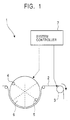
- Fig. 1 shows the main components of a magnetic recording apparatus according to an embodiment of the present invention.
- a magnetic recording apparatus 1 includes a capstan motor 3 for running a magnetic tape 2; magnetic heads 4 and 5 which come into contact with the magnetic tape 2 and which write data on the magnetic tape 2; a rotating drum 6 for rotating and driving the magnetic heads 4 and 5; and a system controller 7 for controlling the running speed of the magnetic tape 2.
- the magnetic tape 2 is, for example, a video tape on which image data and audio data are recorded.
- recording is performed in digital recording formats such as the DV format and the DVCAM format. In such cases, as shown in Fig. 1, the magnetic heads 4 and 5 are used.
- the magnetic heads 4 and 5 are arranged on a cylindrical surface of the rotating drum 6 having a cylindrical shape.
- the magnetic heads 4 and 5 are opposed to each other at 180 degrees with respect to the rotation axis.
- the precise positions at which the magnetic heads are placed and the number of magnetic heads are not limited to those in this embodiment.
- the rotating drum 6 rotates at a constant speed.
- the magnetic tape 2 runs so as to wind itself around the cylindrical surface of the rotating drum 6.
- the magnetic heads 4 and 5 come into contact with the magnetic tape 2.
- the rotating direction of the rotating drum 6 is at a predetermined angle with respect to the running direction of the magnetic tape 2.
- the magnetic heads 4 and 5 which are rotated and driven by the rotating drum 6 diagonally and alternately scan the magnetic tape 2 at this angle, thus writing data to the magnetic tape 2.
- the magnetic heads 4 and 5 write data in such a manner as to write to a portion of an area recorded by the previous scan. In other words, the overlapping portion is overwritten.
- a portion of the recorded area excluding the overlapping portion is the recording track width.
- the recording track width varies with the running speed of the magnetic tape 2.
- the magnetic recording apparatus 1 uses the system controller 7 to control the running speed of the magnetic tape 2, thereby changing the recording track width. As a result, the magnetic recording apparatus 1 can record data in a plurality of recording formats.
- Recording formats of the magnetic tape 2 include, for example, the DV format and the DVCAM format.
- the DV format uses a recording track width of 10 ⁇ m
- the DVCAM format uses a recording track width of 15 ⁇ m.
- the two recording formats will now be described.
- Fig. 2 shows a track pattern formed by recording the magnetic tape 2 in the DV format.
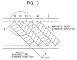
- Fig. 3 shows a track pattern formed by recording the magnetic tape 2 in the DVCAM format.
- the magnetic tape 2 which has a tape width of 6.35 mm is used.
- the rotating speed of the magnetic heads 4 and 5 for writing data is the same in both DV and DVCAM formats.
- the recording track width is made different based on the difference in the running speed of the magnetic tape 2.
- data is written by the two magnetic heads 4 and 5 having different azimuth angles.
- the magnetic heads 4 and 5 are arranged on the cylindrical surface of the rotating drum 6 and are opposed to each other at 180 degrees with respect to the rotation axis.
- the rotating direction of the rotating drum 6 is at a predetermined angle with respect to the magnetic tape 2.
- the magnetic heads 4 and 5 diagonally scan the magnetic tape 2 at this angle and form the track patterns shown in Figs. 2 and 3.
- recording tracks 21, 23, and 25 formed by one magnetic head 4 are referred to as odd tracks, and recording tracks 22 and 24 formed by the other magnetic head 5 are referred to as even tracks.
- recording tracks 22 to 25 compressed and coded image signals, audio signals, and system information such as positional information are recorded.
- the rotating drum 6 is rotated at 9000 rpm, and the magnetic tape 2 runs at 18.831 mm/s. As a result, the track width of each of the recording tracks 21 to 25 is 10 ⁇ m.
- recording tracks 31 and 33 which are referred to as odd tracks, are formed by the magnetic head 4, and recording tracks 32 and 34, which are referred to as even tracks, are formed by the magnetic head 5.
- recording tracks 31 to 34 image signals, audio signals, and system information are recorded.
- the rotating speed of the rotating drum 6 is 9000 rpm, which is the same as in the DV format.
- the running speed of the magnetic tape 2 is 28.247 mm/s.
- the track width of each of the recording tracks 31 to 34 is 15 ⁇ m.
- Fig. 4 is an enlarged view of section A in Fig. 2.
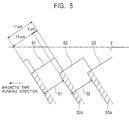
- Fig. 5 is an enlarged view of section B in Fig. 3.
- the recording track width for the DV format is 10 ⁇ m, and the recording track width for the DVCAM format is 15 ⁇ m.
- the recording width of the magnetic heads 4 and 5 is larger than these recording tracks, namely, 17 ⁇ m. Assuming that the running speed of the magnetic tape 2 conforms to the specifications for the DV format and the DVCAM format, the area recorded by each of the magnetic heads 4 and 5 overlaps part of a recording track recorded by the previous scan. In the overlapping portion, old data is overwritten by new data.
- a recording area 41 is recorded by the magnetic head 4.
- a recording area 42 is recorded by the magnetic head 5 in the subsequent scan.
- An overlapping portion 42a is overwritten by the magnetic head 5.
- the width of the overlapping portion 42a overwritten by the subsequent scan that is, 7 ⁇ m, is subtracted from the recording width of the recording area 41 which is recorded by the magnetic head 4, namely, 17 ⁇ m, and data in an area with the recording width of 10 ⁇ m is used as the effective recording track 21.
- the width of the overlapping portion 43a is subtracted from the recording width of the recording area 42, and hence data in an area with the recording width of 10 ⁇ m becomes effective as the recording track 22.
- a recording area 51 is recorded by the magnetic head 4, and a recording area 52 is recorded by the magnetic head 5 in the subsequent scan.
- An overlapping portion 52a is overwritten by the magnetic head 5.
- the subsequent scan is performed by the magnetic head 4
- a recording area 53 is recorded, and an overlapping portion 53a is overwritten.
- the running speed of the magnetic tape 2 is faster than that in the DV format.
- the width of the overlapping portion 52a overwritten by the subsequent scan namely, 2 ⁇ m, is subtracted from the recording width of the recording area 51 by the magnetic head 4, that is, 17 ⁇ m.
- the width of the overlapping portion 53a is subtracted from the recording width of the recording area 52, and hence data in an area with the recording width of 15 ⁇ m becomes effective as the recording track 32.
- a lateral portion of an area recorded by the previous scan is overwritten by each scan performed by the magnetic head 4 or 5.
- the effective recording track width is changed to a desired width in accordance with the running speed of the magnetic tape 2.
- a magnetic recording apparatus which has a fewer number of components and which is capable of recording in a plurality of formats can be implemented at a reduced manufacturing cost.
- Fig. 6 shows an example of the structure of a driving mechanism and a recording processing section of the magnetic recording apparatus 1 according to the embodiment of the present invention.
- the same reference numerals are given to components corresponding to those in Fig. 1.
- a driving mechanism 60 of the magnetic recording apparatus 1 includes the capstan motor 3 for running the magnetic tape 2; the magnetic heads 4 and 5 for recording data on the magnetic tape 2; the rotating drum 6 for rotating and driving the magnetic heads 4 and 5 which are provided thereon; reels 61 and 62 for rewinding the magnetic tape 2; tension arms 63 and 64 for adjusting the tension of the magnetic tape 2; and guide rollers 65 and 66 for guiding the running of the magnetic tape 2.
- the magnetic tape 2 is fed under a predetermined tension and at a predetermined speed by the rotation of the capstan motor 3.
- the capstan motor 3 rotates, the magnetic tape 2 which is wound around the reel 61 is fed so that the magnetic tape 2 winds itself around the rotating drum 6 through the tension arm 63 by the guide rollers 65 and 66.
- the rotating drum 6 has a cylindrical shape.
- the magnetic heads 4 and 5, which are provided on the cylindrical surface, are opposed to each other at 180 degrees with respect to the rotation axis.
- the rotating drum 6 rotates at a predetermined angle with respect to the running direction of the magnetic tape 2.
- the magnetic heads 4 and 5 which are rotated and driven alternately scan the magnetic tape 2 and write data to the magnetic tape 2.
- the magnetic tape 2 on which data is written is released from the rotating drum 6, and subsequently the magnetic tape 2 is rewound on the reel 62 through the capstan motor 3 and the tension arm 64.
- a recording processing section 70 includes an interface 71 to which an image signal is input; a frame memory 72 for storing data for one frame of the input image signal; a DV/DVCAM signal processing circuit 73 for converting the image signal in accordance with a recording format; a REC amplifier 74 for amplifying the converted image signal and transferring the amplified image signal to the magnetic heads 4 and 5; and the system controller 7 for controlling the operation of each component.
- These processing circuits are implemented as integrated circuits which are formed of, for example, semiconductor ICs including processors and volatile read only memories (ROMs).
- the interface 71 is, for example, an IEEE 1394 interface or an input terminal to which analog images and audio are input.
- the system controller 7 receives a recording start signal, the image signal is input frame by frame from the interface 71 to the frame memory 72.
- the DV/DVCAM signal processing circuit 73 reads the image signal from the frame memory 72 and performs predetermined signal conversion such as encoding, appending of system information, error correction, and 24/25 conversion.
- the system controller 7 controls the rotating speed of the capstan motor 3 and the rotating drum 6.
- the signal that has undergone the predetermined processing is transferred from the DV/DVCAM signal processing circuit 73 to the REC amplifier 74 in accordance with the write timing of the magnetic heads 4 and 5.
- the signal amplified by the REC amplifier 74 is transferred to the magnetic heads 4 and 5 and is written on the magnetic tape 2.
- the system controller 7 drives the rotating drum 6 at a rotating speed of 9000 rpm.
- the system controller 7 controls the rotating speed of the capstan motor 3 in order that the running speed of the magnetic tape 2 is 18.831 mm/s in the DV format and 28.247 mm/s in the DVCAM format.
- the magnetic heads 4 and 5 write to the magnetic tape 2 while writing new data in a portion of an area recorded by the previous scan, which is adjacent to the currently written area. As a result, the same magnetic heads 4 and 5 can form a recording track width of 10 ⁇ m in the DV format and 15 ⁇ m in the DVCAM format on the magnetic tape 2.
- the present invention is described with reference to the magnetic recording apparatus as the embodiment, the present invention is also applicable to a magnetic recorder and player capable of recording and playing a magnetic tape.
Landscapes
- Engineering & Computer Science (AREA)
- Signal Processing (AREA)
- Signal Processing For Digital Recording And Reproducing (AREA)
- Digital Magnetic Recording (AREA)
- Recording Or Reproducing By Magnetic Means (AREA)
Abstract
Description
Claims (5)
- A magnetic recording apparatus for recording data on a magnetic tape, comprising:magnetic-tape running means for running the magnetic tape;running-speed control means for controlling the running speed of the magnetic tape;rotating and driving means which has a cylindrical shape and which rotates at a constant speed and at a predetermined angle with respect to the running direction of the magnetic tape; anddata writing means which is provided on a cylindrical surface of said rotating and driving means and which is rotated, said data writing means scanning the magnetic tape at a predetermined angle and writing data while always overwriting data in a lateral portion of an area written by the previous scan.
- A magnetic recording apparatus according to Claim 1, wherein two of said data writing means are provided at mutually opposing positions, separated by 180 degrees with respect to the rotation axis of said rotating and driving means, which write data by alternately scanning the magnetic tape.
- A magnetic recording apparatus according to Claim 1, wherein said running-speed control means controls the running speed of the magnetic tape in order that a portion other than the overwritten portion of the written area has a width of 10 µm.
- A magnetic recording apparatus according to Claim 1, wherein said running-speed control means controls the running speed of the magnetic tape in order that a portion other than the overwritten portion of the written area has a width of 15 µm.
- A magnetic recording method for recording data on a magnetic tape, comprising the steps of:scanning the magnetic tape by a magnetic head which rotates at a constant speed and at a predetermined angle with respect to the running direction of the magnetic tape and writing data while always overwriting data in a lateral portion of an area written by the previous scan; andcontrolling the running speed of the magnetic tape in order that the width of a portion other than the overwritten portion of the written area has a predetermined value.
Applications Claiming Priority (2)
| Application Number | Priority Date | Filing Date | Title |
|---|---|---|---|
| JP2000155704A JP2001338402A (en) | 2000-05-26 | 2000-05-26 | Magnetic recording device and magnetic recording method |
| JP2000155704 | 2000-05-26 |
Publications (2)
| Publication Number | Publication Date |
|---|---|
| EP1158496A2 true EP1158496A2 (en) | 2001-11-28 |
| EP1158496A3 EP1158496A3 (en) | 2002-05-15 |
Family
ID=18660599
Family Applications (1)
| Application Number | Title | Priority Date | Filing Date |
|---|---|---|---|
| EP01112171A Withdrawn EP1158496A3 (en) | 2000-05-26 | 2001-05-17 | Magnetic recording apparatus and magnetic recording method |
Country Status (5)
| Country | Link |
|---|---|
| US (1) | US6724557B2 (en) |
| EP (1) | EP1158496A3 (en) |
| JP (1) | JP2001338402A (en) |
| KR (1) | KR100773255B1 (en) |
| CN (1) | CN1180414C (en) |
Family Cites Families (15)
| Publication number | Priority date | Publication date | Assignee | Title |
|---|---|---|---|---|
| HU184512B (en) * | 1982-03-05 | 1984-09-28 | Kontakta Alkatreszgyar | Retainer for clamping workpiece |
| US4689706A (en) * | 1982-09-15 | 1987-08-25 | Ampex Corporation | Apparatus and method for adjusting the respective positions of a magnetic head and video information along a magnetic track |
| CA1243774A (en) * | 1983-06-15 | 1988-10-25 | Takaharu Noguchi | Pcm signal recording/reproducing apparatus |
| US5119255A (en) * | 1984-08-16 | 1992-06-02 | Ampex Corporation | Magnetic saturation controlled scanning magnetic transducer |
| JPH0679400B2 (en) * | 1987-05-29 | 1994-10-05 | 松下電器産業株式会社 | Magnetic recording / reproducing device |
| EP0372481B1 (en) * | 1988-12-06 | 1995-08-09 | Mitsubishi Denki Kabushiki Kaisha | Magnetic recording and reproducing apparatus |
| JPH05122647A (en) * | 1991-10-30 | 1993-05-18 | Sony Corp | Digital video tape recorder |
| US5276566A (en) * | 1991-11-20 | 1994-01-04 | Hewlett-Packard Company | Recording/reading high density data tracks with backward compatibility |
| US5353176A (en) * | 1991-12-09 | 1994-10-04 | Hitachi, Ltd. | Method of reproducing magnetic recording data and a magnetic storage system using switching between plural heads provided to a track |
| JPH0612606A (en) * | 1992-06-29 | 1994-01-21 | Sony Corp | VTR device that can record for a long time |
| US5506668A (en) * | 1994-01-25 | 1996-04-09 | Eastman Kodak Company | Image forming apparatus having toner removing device |
| KR100292131B1 (en) * | 1997-06-05 | 2001-06-01 | 가나이 쓰도무 | A recording and reproducting apparatus, and a reproducting apparatus |
| JP4081881B2 (en) * | 1998-03-02 | 2008-04-30 | ソニー株式会社 | Digital signal magnetic recording apparatus and method, digital signal magnetic reproducing apparatus and method, and tape-shaped recording medium |
| EP0978837A1 (en) * | 1998-08-07 | 2000-02-09 | Hewlett-Packard Company | Intelligent tracking offset system for tape cartridge data storage |
| JP4178620B2 (en) * | 1998-10-27 | 2008-11-12 | ソニー株式会社 | Magnetic recording / reproducing device |
-
2000
- 2000-05-26 JP JP2000155704A patent/JP2001338402A/en active Pending
-
2001
- 2001-05-17 EP EP01112171A patent/EP1158496A3/en not_active Withdrawn
- 2001-05-24 KR KR1020010028673A patent/KR100773255B1/en not_active Expired - Fee Related
- 2001-05-25 US US09/865,263 patent/US6724557B2/en not_active Expired - Fee Related
- 2001-05-25 CN CNB011189703A patent/CN1180414C/en not_active Expired - Fee Related
Also Published As
| Publication number | Publication date |
|---|---|
| JP2001338402A (en) | 2001-12-07 |
| EP1158496A3 (en) | 2002-05-15 |
| KR100773255B1 (en) | 2007-11-05 |
| US6724557B2 (en) | 2004-04-20 |
| CN1180414C (en) | 2004-12-15 |
| KR20010107726A (en) | 2001-12-07 |
| US20020048111A1 (en) | 2002-04-25 |
| CN1332452A (en) | 2002-01-23 |
Similar Documents
| Publication | Publication Date | Title |
|---|---|---|
| JPH09504404A (en) | Video / audio signal recording / reproducing apparatus for inclined track of magnetic tape and magnetic tape for the apparatus | |
| US6658195B1 (en) | Magnetic recording and playback method and apparatus | |
| JPS585461B2 (en) | magnetic tape recording device | |
| US6724557B2 (en) | Magnetic recording apparatus and magnetic recording method | |
| JP3303547B2 (en) | Rotary head type recording / reproducing device | |
| EP1043725B1 (en) | Magnetic recording and/or reproduction methods and apparatus | |
| JP3252989B2 (en) | Magnetic recording / reproducing device | |
| JPH0636209A (en) | Tape recording and replay apparatus | |
| JP2956349B2 (en) | Magnetic recording / reproducing device | |
| JP3074767B2 (en) | Rotating head drum | |
| US6490108B1 (en) | Digital data recording method and apparatus, digital data reproducing apparatus, and magnetic tape therefor | |
| JP2933776B2 (en) | Magnetic recording / reproducing device | |
| JP2942632B2 (en) | Helical scan method and non-native format readout device | |
| WO2002049030A1 (en) | Magnetic recording/reproducing method and magnetic recorder/reproducer | |
| JP3249259B2 (en) | Digital signal recording device and reproducing device | |
| JPH08315308A (en) | Magnetic recording / reproducing device | |
| JPH0855301A (en) | Rotating head type recording / reproducing device | |
| JPH10134302A (en) | Recording track straightness adjustment device | |
| JPH0744836A (en) | Rotating magnetic head and magnetic recording pattern recording method | |
| JP2000099903A (en) | Information reading method and device | |
| JP2001176041A (en) | Information recording / reproducing apparatus and method | |
| JP2000113433A (en) | Magnetic recording / reproducing apparatus and magnetic recording / reproducing method | |
| JPH07230612A (en) | Recording / playback device | |
| JPH08306135A (en) | Signal recording device, signal reproducing device, and tape-shaped recording medium | |
| JPS62165704A (en) | Recording and reproducing device |
Legal Events
| Date | Code | Title | Description |
|---|---|---|---|
| PUAI | Public reference made under article 153(3) epc to a published international application that has entered the european phase |
Free format text: ORIGINAL CODE: 0009012 |
|
| AK | Designated contracting states |
Kind code of ref document: A2 Designated state(s): AT BE CH CY DE DK ES FI FR GB GR IE IT LI LU MC NL PT SE TR |
|
| AX | Request for extension of the european patent |
Free format text: AL;LT;LV;MK;RO;SI |
|
| PUAL | Search report despatched |
Free format text: ORIGINAL CODE: 0009013 |
|
| AK | Designated contracting states |
Kind code of ref document: A3 Designated state(s): AT BE CH CY DE DK ES FI FR GB GR IE IT LI LU MC NL PT SE TR |
|
| AX | Request for extension of the european patent |
Free format text: AL;LT;LV;MK;RO;SI |
|
| 17P | Request for examination filed |
Effective date: 20021015 |
|
| AKX | Designation fees paid |
Designated state(s): DE FR GB |
|
| 17Q | First examination report despatched |
Effective date: 20050318 |
|
| STAA | Information on the status of an ep patent application or granted ep patent |
Free format text: STATUS: THE APPLICATION IS DEEMED TO BE WITHDRAWN |
|
| 18D | Application deemed to be withdrawn |
Effective date: 20081202 |