EP1158463A2 - A method of compensating for MTF in a digital image channel - Google Patents
A method of compensating for MTF in a digital image channel Download PDFInfo
- Publication number
- EP1158463A2 EP1158463A2 EP01201080A EP01201080A EP1158463A2 EP 1158463 A2 EP1158463 A2 EP 1158463A2 EP 01201080 A EP01201080 A EP 01201080A EP 01201080 A EP01201080 A EP 01201080A EP 1158463 A2 EP1158463 A2 EP 1158463A2
- Authority
- EP
- European Patent Office
- Prior art keywords
- digital image
- mtf
- filter
- image channel
- devices
- Prior art date
- Legal status (The legal status is an assumption and is not a legal conclusion. Google has not performed a legal analysis and makes no representation as to the accuracy of the status listed.)
- Withdrawn
Links
Images




Classifications
-
- G—PHYSICS
- G06—COMPUTING OR CALCULATING; COUNTING
- G06T—IMAGE DATA PROCESSING OR GENERATION, IN GENERAL
- G06T5/00—Image enhancement or restoration
- G06T5/73—Deblurring; Sharpening
- G06T5/75—Unsharp masking
Definitions
- the invention relates generally to the field of digital image processing and, more particularly, to a method of compensating for MTF degradations in the imaging chain.
- MTF Modulation Transfer Function
- the MTF of several components may be cascaded (multiplicatively) by techniques well known in the art (see for example commonly-assigned US-A-5,696,850.)
- the MTF of multiple devices or an entire system may be determined by cascading the MTF of the appropriate devices.
- the most appropriate place to compensate for the MTF of the device is at the point that the device is used. For instance, if a CCD is used to capture an image in a digital camera, the MTF of the CCD should be compensated just after the image is captured. Changes to the original resolution and the inclusion of devices with additional MTF losses to the imaging chain make the compensation for the MTF of a device a much more difficult problem if the device compensation is separated from the location of the device in the image chain.
- the term "compensation" must be defined.
- a restrictive definition of compensation has been used and it requires that the sequential combination of the device and the device compensation has an MTF of 1.0 for all frequencies.
- This strict device compensation would be accomplished with an inverse filter, such as described by Gonzalas and Woods, in Digital Image Processing , Addison-Wesley Publishing Company, 1992, pp. 270-272.
- the inverse filter is the design goal specified by commonly-assigned US-A-5,696,850 when describing a method of performing a single sharpening operation to compensate for both input and output device.
- Non-strict device compensation is a process by which the MTF of a device is restored within a reasonable delta of 1.0 for as great a frequency range as possible, giving preference to the lower frequencies. Note that the definitions of the terms "reasonable delta" and "frequency range” may vary.
- Ishii and others., in US-A-5,978,522 describes a method of modifying the sharpness characteristic of a digital image similar to the inverse filter described by commonly-assigned US-A-5,696,850.
- Ishii utilizes an aim specific to the source of the image, or a user's preference, rather than an aim magnitude frequency response of 1.0 for all frequencies.
- This method has no guarantees that the compensation will not require high gains which will greatly amplify the noise in the system.
- this method may generate a compensation filter that is very large, since the filter is generated directly from an inverse Fourier transform of a filter aim. Also, each frequency is considered of equal importance to the correction.
- the Wiener filter (commonly known in the art, for example described by Gonzalas and Woods, in Digital Image Processing , Addison-Wesley Publishing Company, 1992, pp. 279-282) is actually an attempt to apply a non-strict device compensation.
- the Wiener filter requires knowledge of both the magnitude and phase of the frequency response of the device, as well as the power spectrum of both the signal and the noise (although approximations can be made if the power spectra are unknown.)
- the Wiener filter uses the signal-to-noise-ratio (SNR) to limit the gain applied to any specific frequency.
- SNR signal-to-noise-ratio
- the Wiener filter is computationally intensive, requiring the use of a Fourier transform of the image (although the correction spectrum need be computed only once per device.)
- the desirable traits of the Wiener filter should be preserved when designing a strategy for non-strict device compensation.
- the MTF in one or more devices in the imaging chain can be effectively compensated for and provide a compensated digital image channel.
- the filter is developed from the aim response by using a weighted fitting in the frequency domain.
- the present invention utilizes a digital image which is typically a two-dimensional array of red, green, and blue pixel values, or a single monochrome pixel value corresponding to light intensities.
- a preferred embodiment is described with reference to a digital image of 1024 rows of pixels and 1536 lines of pixels.
- a pixel of a digital image located at coordinates ( x,y ), referring to the x th row and the y th column of the digital image shall herein consist of a triad of values [ r(x,y), g(x y), b(x,y) ] respectively referring to the values of the red, green , and blue digital image channels at location ( x,y ).
- a digital image consists of a certain number of digital image channels. In the case of a digital image consisting of red, green and blue two-dimensional arrays, the image consists of exactly three channels.
- n(x,y) The value of a pixel of a digital image channel n located at coordinates ( x , y ), referring to the x th row and the y th column of the digital image channel shall herein be a single value referred to as n(x,y).
- digital image channel will be understood to encompass a single plane of a digital image. For example, if a digital image has red, green and blue components there are three channels. Also if a digital image is specified in terms of luminance, there is a luminance channel.
- the present invention can be applied to one or more digital image channels. For purposes of the present invention each digital image channel may be considered to be a digital image.
- the present invention relates to a method for processing a digital image channel to compensate for MTF degradations in one or more devices in an imaging chain from capture to output.
- the MTF can be that of a single device which provides significant distortion of a digital image channel either during capture or processing.
- the present invention may be applied to a single digital image channel (for instance, the red channel, the green channel, the blue channel, or the luminance channel), several digital image channels of a digital image, or all the digital image channels of the digital image.
- a single digital image channel for instance, the red channel, the green channel, the blue channel, or the luminance channel
- several digital image channels of a digital image or all the digital image channels of the digital image.
- the digital image may, for example, be captured with a digital camera.
- the digital image may also one of a motion picture sequence.
- the digital image may not represent any actual scene, and may be a simulated computer rendering or a graphic drawing or design.
- the digital image channel is input to the MTF compensator 8.
- the purpose of the MTF compensator 8 is to prepare the frequency content of the digital image channel for the MTF degradation that occurs when the image is passed through the devices or image transforms causing the MTF losses described by the MTF.
- the MTF is assumed to be caused by a device 10.
- this device 10 is an output device, such as a CRT monitor, a CRT silver halide printer, an ink jet printer or the like.
- input devices such as CCDs, film or the like also have associated MTFs, in which case the MTF compensator 8 may follow the device 10.
- the response of an observer (human or otherwise) may be considered to be a device 10 in the imaging chain. Therefore, the digital image channel may be compensated for the MTF of the observer (in the art the MTF of a human observer is referred to as the contrast sensitivity function) with the method described in this embodiment.
- the function of the MTF compensator 8 is to apply a filter to the digital image channel to provide a new digital image channel compensated for MTF by modifying the digital image input to the MTF compensator 8 in such a way that the image output from the device 10 is as similar as practically possible (within some delta) to the image input to the MTF compensator 8 in terms of image structure and detail.
- the MTF compensator 8 performs an unsharp mask operation as is well known by those skilled in the art of image processing.
- the unsharp mask utilizes a gain factor ⁇ and a lowpass filter provided by a filter determiner 4.
- the lowpass filter is a Gaussian filter.
- a Gaussian filter has been selected as the filter of choice because it has several desirable characteristics.
- a two dimensional Gaussian filter is separable into two one dimensional Gaussian filters, one horizontal and the other vertical.
- a radially symmetric Gaussian filter had a frequency response that is radially symmetric.
- a Gaussian filter is the only FIR (finite impulse response) lowpass filter that has the characteristics of separability and radial symmetry in both the space and frequency domains.
- the MTF compensator 8 applies an unsharp mask operation in which the gain factor ⁇ provided by the determiner 2 and the characteristics of the lowpass filter produced by the filter determiner 4 are optimized in order to provide an effective compensation for the MTF.
- the ⁇ determiner 2 inputs device information such as SNR (Signal to Noise Ratio) of the device 10 or the imaging chain, power spectrum, dynamic range of the device 10 or the imaging chain, and any other information which may be a reason for setting a limit on the gain of the unsharp mask.
- the gain factor ⁇ determiner 2 simply sets the value of ⁇ to 2.5. In this manner, the gain factor ⁇ is predetermined. It is recommended that the value of ⁇ not exceed 5.0 for typical devices such as those previously mentioned.
- the filter determiner 4 inputs both the value of ⁇ output from the gain factor ⁇ determiner 2 and the MTF.
- the operation of the filter determiner 4 is to determine the Gaussian filter parameter ⁇ corresponding to the lowpass filter that, when used in the unsharp mask of the MTF compensator 8 along with gain ⁇ , provides an optimal compensation for MTF.
- the filter determiner 4 operated by performing a weighted least squares fit (over ⁇ ) in the frequency domain of the magnitude response of a Gaussian filter to an ideal filter response. The weighted least squares fit and the creation of an ideal filter response from the device MTF will be described in greater detail hereinbelow.
- the filter determiner 4 requires the inputs of the MTF data of the device 10 and the gain factor value ⁇ .Note that the MTF data may be dependent upon which digital image channel has been input to the MTF compensator 8. For example, the MTF of a digital printer for the red digital image channel is usually significantly different from the MTF of the same digital printer for the blue digital image channel. It is important the appropriate MTF data (relating to the digital image channel input to the MTF compensator 8) is input to the filter determiner 4. Additionally, the MTF data corresponding to the device 10 may need to be specified according to direction. It is common to measure the MTF of a device in both the "fast” and "slow" scan directions.
- the MTF of a device may be specified as a full two dimensional response function rather than two one-dimensional responses.
- An exploded block diagram of the filter determiner 4 may be viewed in FIG. 2.
- the MTF data input to the filter determiner 4 is input to the frequency normalizer 40.
- MTF data is preferably specified in the present invention as a two column table, the first column relating to frequency and the second column relating to the magnitude of the frequency response (MTF) corresponding with that frequency in the specified scan direction.
- the MTF of a CRT printer in combination with a typical photographic paper is given in the following table: Frequency (cycles/mm) MTF of Red channel in Honzontal Direction 0.000000e+00 1.000000e+00 5.000000e-01 9.512699e-01 1.000000e+00 8.171171e-01 1.500000e+00 6.699246e-01 2.000000e+00 5.289917e-01 2.500000e+00 4.025696e-01 3.000000e+00 2.946993e-01 3.500000e+00 2.085783e-01 4.000000e+00 1.459891e-01 4.500000e+00 1.068113e-01 5.000000e+00 8.508064e-02 5.500000e+00 7.349594e-02 6.000000e+00 6.475624e-02 6.500000e+00 5.156054e-02
- the purpose of the frequency normalizer 40 is to convert the frequency axis of the MTF data (commonly specified in cycles
- P the resolution of the printer in dots per inch
- f cmm the frequency represented in units of cycles/mm.
- a normalized frequency of 1.0 represents the highest frequency possible in the digital image channel (each cycle is 2 pixels).
- the MTF data can be expressed so that a normalized frequency other than 1.0 represents the highest possible frequency of the digital image channel. For example it is common to represent the maximum possible frequency of a sampled signal as 1 ⁇ 2 or ⁇ .
- MTF data is generated for any frequency for which MTF data does not exist by use of a spline through existing data points. (The extrapolated MTF data is forced to be within the range of 0.0 and 1.0.)
- the normalized MTF data output from the frequency normalizer 40 is then input to the filter aim response generator 42.
- the filter aim response generator 42 determines the aim of the lowpass filter to used in an unsharp mask framework with the specified gain factor ⁇ in order to determine the "best" device compensation possible, without regard to the constraints of digital filter design.
- a series of steps is required to generate the filter aim response from the device 10 MTF data.
- capital variables refer to the Fourier Transform of the image signals or filters with the corresponding lower-case designation. For instance, with regard to FIG.
- B(u,v) represents the Fourier transform of the signal b(x y)
- F(u,v) is the Fourier Transform of the lowpass filter f(i,j) used in the unsharp mask.
- Such a variation of the unsharp mask equation is well known in the art, and the effects may be cascaded throughout the development of a preferred embodiment of the present invention without substantially altering the performance of the method described herein.
- the MTF of the serial combination of an unsharp mask 12 and the device 10 shown in FIG. 3 is given as the product of the MTFs of these two components:
- ⁇ (1-
- is the magnitude of the frequency response of the device 10 under consideration.
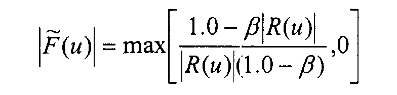
- the goal of the filter aim response generator 42 is to find
- the filter aim response generator 42 computes filter aim response
- the MTF is assumed to be separable in the vertical and horizontal directions.
- the MTF of the device in the horizontal direction is represented by
- the MTF of the device in the vertical direction is represented as
- the filter aim response generator 42 outputs two filter aim responses,
- the problem of filter design is greatly simplified by considering only a single dimension (vertical or horizontal ) of MTF data at a time.
- the preceding equations relate the method by which the filter aim response generator 42 determines a filter aim response dependent upon the gain factor ⁇ and the MTF of the device 10, denoted by
- for example, output from the filter aim response generator 42 is then input to the weighted least squares fitter 44.
- the weighted least squares fitter 44 constructs a filter f and( i ) whose frequency response
- f and( i ) may be calculated as the inverse Fourier transform of
- a filter produced by this method may not have good radial symmetry properties when considered together with f and (j) .
- f and ( i ) is forced to be a Gaussian filter, as will be detailed hereinbelow.
- the filters f and ( i ) and f and ( j ) are preferably constructed from
- ( u, v) may be output from the filter aim response generator 42 and then input to the weighted least squares fitter 44.
- the weighted least squares fitter 44 constructs a filter f and ( i,j ) whose frequency response
- f and ( i,j ) may be calculated as the inverse Fourier transform of
- f and ( i ,j ) may then consist of a large number of samples.
- the filter f and ( i,j ) may be constrained to be a Gaussian filter.
- a Gaussian filter is well known in the art of digital signal processing.
- the Gaussian filter f G (m) is obtained by normalizing f U (m) such that the sum of the filter coefficients (and consequently the DC gain) equals 1.0.
- the weighted least squares fitter 44 determines an optimal lowpass filter to compensate for the MTF by performing a weighted least squares fit in the frequency domain.
- the weighted least squares fitter 44 produces a filter from the filter aim response.
- the operation of the weighted least squares fitter 44 is herein described with reference to the one-dimensional filter aim response
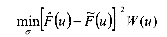
- , is the filter f and ( i ) which minimizes the following expression: where W(u) is a weighting function. Possibilities for the weighting function W(u) will be discussed herein below.
- the preferred embodiment of the weighted least squares fitter 44 assumes that the filter f and ( i ) is a Gaussian filter. Since a Gaussian filter is completely specified with ⁇ , the number of samples per standard deviation of the Gaussian filter, the optimization problem is reduced to an optimization over ⁇ : Optimization techniques and software packages capable of solving the minimization problem are commonly available. Note that the preferred embodiment utilizes a minimization of an expression containing a squared difference. Many other expressions, for example absolute difference, are available for expressing the distance between two functional expressions. This disclosure is intended to cover all such expressions.
- the weighting function is formed from the filter aim response,
- the weighting function W(u) may also be a function of the MTF of the device 10, for example.
- K 2 to achieve a good compensation of the MTF.
- Increasing the value of K causes the weighted least squares fitter 44 to more accurately fit the lower frequencies of the desired filter aim response.
- the weighting function W(u) may be the contrast sensitivity function of the human visual system. This alternative is especially applicable when the device 10 is an output device. Functions of this kind are well known in the art of image processing.
- the weighted least squares fitter 44 outputs the results for both the horizontal and vertical MTFs, represented by ⁇ i and ⁇ j .
- the filter f and ( i ) could be generated by designing a filter similar to the inverse Fourier transform o
- the gain factor B and the digital filter or filters are jointly determined by a gain factor and filter determiner 34. This approach is more general than that of the preferred embodiment, where the gain factor ⁇ and the filter are sequentially determined.
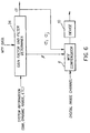
- FIG.4 illustrates how the output of the gain factor ⁇ determiner 2 and the filter determiner 4 are utilized to achieve an MTF compensation.
- the MTF compensator 8 inputs the gain factor ⁇ and ⁇ i and ⁇ j output from the filter determiner 4.
- the filter generator 28 constructs and outputs two normalized one-dimensional Gaussian filters f and ( i ) and f and ( j ), the equation of which has been disclosed hereinabove.
- the filter determiner 4 may pass one or more filters directly to the filter generator 28, in which case the filter generator 28 would simply output the filter or filters.
- the digital image channel is passed to the blurrer 22.
- the purpose of the blurrer 22 is to perform a convolution of the digital image channel with the filter or filters input from the filter generator 28 in order to form a lowpass image.
- the blurrer 22 operates by convolving the digital image channel by f and ( i ) in a first blurring stage.
- a second blurring stage follows the first by convolving the output of the first blurring stage by the filter f and ( i ).
- the blurrer 22 performs only a single convolution with the filter f and ( i,j ).
- the lowpass signal output from the blurrer 22 is input to the adder 24 along with the digital image channel.
- This modified digital image channel is output from the MTF compensator 8 and is prepared for the MTF of the device 10, the MTF of the system, or the MTF of a combination of devices.
- an imaging chain contains one or more devices.
- two devices 10 and 30 shown For example, in the case of a system that scans film and then prints the resulting image, there is a CCD for capturing the image, and the device 10 (an output device such as a CRT monitor for viewing the image.)
- the input device 30 may be the capture CCD, the film, the camera lens, or any combination of these devices.
- Each of these devices has an associated MTF.
- FIG 5 illustrates that a MTF compensation 8a can be created for the input device 30. This MTF compensation 8a would utilize the MTF of the input device 30 for generating the gain factor ⁇ and the filter.
- MTF compensator 8b can be utilized in order to compensate for an output device 10, as previously described.
- MTF compensators 8a and 8b can utilize optimized gain factors and filters generated specifically for the devices 10 and 30. Notice that it is generally advisable to apply the MTF compensator 8 as near in the imaging chain as possible to the device for which the MTF compensator is optimized. In the case of an input device 30, the MTF compensator 8a immediately follows the device 30. However, in a practical system it is conceivable that the MTF compensator 8 may be separated from the device 30 by several image processing steps, for instance noise reduction. In the case of an output device 10, the MTF compensator 8b is applied as the last operation before the image is passed to the device 10.
- Those skilled in the art may insert an image processing operation between the MTF compensator 8b and the output device 10 if doing so saves computational cost. For example a cropping operation will reduce the number of pixels in the digital image channel, so computation should not be spent computing MTF compensation at pixel locations that are to be cropped.
- the MTF compensator 8 can be used for the purpose of compensating for the combined effects of all devices in the imaging chain. If the image processing unit 32 contains no changes to the image spatial resolution, configuring the MTF compensator 8 to counteract the MTF of the input device 30 and the output device 10 is a simply matter of inputting to the filter determiner 4 the multiplication of the two devices' MTFs (a cascade of all the MTFs of the devices in the imaging chain is referred to as the system MTF.) Combining the MTF responses of several devices in an imaging chain to form a system MTF is well known in the art. Commonly-assigned US-A-5,696,850 describes a method of generating a system MTF even if the image processing unit 32 contains operations which modify the image spatial resolution, such as decimation or interpolation.
- the gain factor B and the digital filter or filters are jointly determined by a gain factor and filter determiner 34.
- This approach is more general than that of the preferred embodiment, where the gain factor ⁇ and the filter are sequentially determined.
- FIG. 7 shows a flowchart for a preferred embodiment of the present invention where digital image channels compensated for MTF of a device are stored on a network server such that they can be made available via a digital communications network.
- digital image channels 80 are sent to a processing site by a user.
- the user may also send information such as MTF of a printer 102 or a printer identification code.
- this is accomplished by the user supplying photographic film negatives to the processing site, either by mail, or by delivering the negatives to a processing site.
- the negatives can be in a developed or undeveloped form.
- the negatives would then be developed if necessary, and then scanned to produce digital image channels 80.
- the digital image channels 80 could be supplied directly by the user, either over a communications network, or on a computer readable storage medium such as a magnetic disk, a CDROM, or a PCMCIA card.
- the digital image channels 80 could originate from a digital camera, or alternatively could originate from scans of conventional photographic materials such as prints, slides or negatives.
- the digital image channels 80 could also originate from computer generated imagery.
- each digital image channel 80 is processed using a MTF compensator 8 to produce a digital image channel compensated for the MTF of one or more devices.
- the operation of the MTF compensator has been previously described herein.
- a make payment step 85 is used to obtain payment from the user. This can be done using a cash transaction, or by using an obtain payment identifier from user step 86.
- the payment identifier can include information about an account from which payment is to be electronically transferred.
- the payment identifier can include a credit card account where the payment is to be debited.
- Other forms of payment identifiers are also possible including a check, and so forth
- the payment identifier is obtained from the user via a digital communications network such as the internet.
- a store image on network server step 87 is used to make the digital image channel compensated for the MTF of one or more devices 84 available to the user via a digital communications network.
- a digital communications network would include the internet and a local area network.
- the digital image channel compensated for the MTF of one or more devices 84 is made available to the user at a specific internet address. The user may be supplied with a password in order to access the digital image channel compensated for the MTF of one or more devices 84, or alternatively, the digital image channel compensated for the MTF of one or more devices 84 might be publicly available.
- digital image channel compensated for the MTF of one or more devices 84 can be transferred to a location designated by the user via the digital communications network.
- the digital image channel compensated for the MTF of one or more devices 84 could be sent by E-mail, or could be transferred using a file transfer protocol.
- the digital image channel compensated for the MTF of one or more devices 84 can be transferred to a location designated implicitly by the user via the digital communications network.
- the digital image channel compensated for the MTF of one or more devices 84 may be transferred to a location nearest an address specified by the user for printing on an output device.
- the MTF supplied to the filter determiner 4 can be the MTF information associated with a device at the location to which the digital image channel compensated for the MTF of one or more devices 84 is transferred.
- FIG. 8 illustrates an embodiment of the present invention digital image channels compensated for the MTF of one or more devices 84 are accessed by a digital communications network, such as the internet.
- a digital communications network such as the internet.
- an image database 90 is located on a network server 92.
- the image database 90 is used to store digital image channel compensated for the MTF of one or more devices 84 that have been processed using the methods described earlier.
- the network server 92 is connected to a communications network 95.
- the communications network 95 could be the internet, or a local area network.
- a user uses a processor 96 to access the network server 92 via the communications network 95.
- the processor 96 can be a home computer, or alternatively it could be a computer in a retail kiosk, and so forth Typically, the processor would use a monitor 98 for the purpose of displaying preview images, and providing information to the user.
- One or more input devices 100 can be used by the user to provide instructions to the processor 96. Examples of typical input devices would include a keyboard, a mouse, a trackball, a touch pad or a touch screen.
- a printer 102 may also be connected to the processor for providing output prints to the user. Alternatively, a remote printer could also be accessed over the communications network 95.
- a card reader 104 can also be connected to the processor 96 for purposes of reading account information from a credit card or a debit card as part of the obtain payment identifier from user step 86 that was discussed earlier.
- Other network servers can also be attached to the communications network 95.
- a user makes payment via the internet.
- One common way for the user to provide a payment identifier to a service provider would be for him or her to supply a valid credit card number.
- the service provider would then access a user account database 106 on a network server 108 to debit the appropriate payment, which would then be credited to an account specified by the service provider by accessing a service provider account database 110 on another network server 112.
- the service provider would then provide the user access to the digital image channels compensated for the MTF of one or more devices 84 stored in the image database 90.
- a computer program product can have one or more computer readable storage media disposed in different processing locations, each having a computer program stored thereon for performing all the steps of the present invention.
- Each computer readable storage medium can comprise, for example; magnetic storage media such as magnetic disc (such as a floppy disc) or magnetic tape; optical storage media such as optical disk, optical tape, or machine readable bar code; solid state electronic storage devices such as random access memory (RAM), or read only memory (ROM); or any other physical device or medium employed to store a computer program.
- magnetic storage media such as magnetic disc (such as a floppy disc) or magnetic tape
- optical storage media such as optical disk, optical tape, or machine readable bar code
- solid state electronic storage devices such as random access memory (RAM), or read only memory (ROM); or any other physical device or medium employed to store a computer program.
- weighted fitting is a weighted least square fitting which provides a weighting function that is monotomically decreasing with increasing frequencies.
- weighting function is a function of the response of a human visual system.
- the gain factor is determined by the signal to noise ratio in the imaging chain or the dynamic range in the imaging chain or combinations thereof.
- the method wherein the MTF is that of an output device or image capture device in the imaging chain.
- the filter is a Gaussian filter.
Landscapes
- Physics & Mathematics (AREA)
- General Physics & Mathematics (AREA)
- Engineering & Computer Science (AREA)
- Theoretical Computer Science (AREA)
- Image Processing (AREA)
- Facsimile Image Signal Circuits (AREA)
- Studio Devices (AREA)
Abstract
Description
| Frequency (cycles/mm) | MTF of Red channel in Honzontal Direction |
| 0.000000e+00 | 1.000000e+00 |
| 5.000000e-01 | 9.512699e-01 |
| 1.000000e+00 | 8.171171e-01 |
| 1.500000e+00 | 6.699246e-01 |
| 2.000000e+00 | 5.289917e-01 |
| 2.500000e+00 | 4.025696e-01 |
| 3.000000e+00 | 2.946993e-01 |
| 3.500000e+00 | 2.085783e-01 |
| 4.000000e+00 | 1.459891e-01 |
| 4.500000e+00 | 1.068113e-01 |
| 5.000000e+00 | 8.508064e-02 |
| 5.500000e+00 | 7.349594e-02 |
| 6.000000e+00 | 6.475624e-02 |
| 6.500000e+00 | 5.156054e-02 |





Claims (10)
- A method for processing a digital image channel which is part of a digital image to compensate for MTF of one or more devices in an imaging chain from capture to printing comprising the steps of:(a) providing the MTF of the one or more devices in the imaging chain;(b) providing a gain factor, using the MTF to provide an aim response;(c) providing a filter from the aim response; and(d) applying the filter to the digital image channel to provide a new digital image channel.
- A method for processing a digital image channel which is part of a digital image to compensate for MTF of one or more devices in an imaging chain from capture to printing comprising the steps of:(a) providing the MTF of the one or more devices in the imaging chain;(b) providing a gain factor, using the gain factor and the MTF to provide an aim response;(c) providing a filter from the aim response; and(d) applying the filter to the digital image channel to provide a new digital image channel.
- The method of claim 2 wherein the gain factor is predetermined.
- The method of claim 2 wherein the gain factor is determined by the signal to noise ratio in the imaging chain or the dynamic range in the imaging chain or combinations thereof.
- The method of claim 2 wherein the MTF is that of an output device or image capture device in the imaging chain.
- The method of claim 2 wherein the filter is a Gaussian filter.
- A method for processing a digital image channel which is part of a digital image to compensate for MTF of one or more devices in an imaging chain from capture to printing comprising the steps of:(a) providing the MTF of the one or more devices in the imaging chain;(b) providing a gain factor, using the gain factor and the MTF to provide an aim response;(c) providing a filter from the aim response by using a weighted fitting in the frequency domain; and(d) applying the filter to the digital image channel to provide a new digital image channel compensated for the MTF.
- The method of claim 7 wherein the weighted fitting is a weighted least square fitting.
- A method for processing a digital image channel which is part of a digital image to compensate for MTF of one or more devices in an imaging chain from capture to printing and paying for such processed digital image comprising the steps of:(a) a user sending a digital image channel via a communication network to a processing site where the digital image channel is to be processed and paying for such processed digital image channel;(b) processing such digital image channel by:(i) providing the MTF of the one or more devices in the imaging chain;(ii) providing a gain factor, using the MTF to provide an aim response;(iii) providing a filter from the aim response; and(iv) applying the filter to the digital image channel to provide a new digital image channel; and(c) sending the processed digital image channel to a location designated by the user and the user making payment via the communication network for the processed digital image.
- A method for processing a digital image channel which is part of a digital image to compensate for MTF of one or more devices in an imaging chain from capture to printing and paying for such processed digital image comprising the steps of:(a) a user sending a digital image channel via a communication network to a processing site where the digital image channel is to be processed and paying for such processed digital image channel;(b) processing such digital image channel by:(i) providing the MTF of the one or more devices in the imaging chain;(ii) providing a gain factor, using the gain factor and the MTF to provide an aim response;(iii) providing a filter from the aim response; and(iv) applying the filter to the digital image channel to provide a new digital image channel; and(c) sending the processed digital image channel to a location designated by the user and the user making payment via the communication network for the processed digital image.
Applications Claiming Priority (2)
| Application Number | Priority Date | Filing Date | Title |
|---|---|---|---|
| US09/543,082 US6728003B1 (en) | 2000-04-04 | 2000-04-04 | Method of compensating for MTF in a digital image channel |
| US543082 | 2000-04-04 |
Publications (2)
| Publication Number | Publication Date |
|---|---|
| EP1158463A2 true EP1158463A2 (en) | 2001-11-28 |
| EP1158463A3 EP1158463A3 (en) | 2003-09-17 |
Family
ID=24166500
Family Applications (1)
| Application Number | Title | Priority Date | Filing Date |
|---|---|---|---|
| EP01201080A Withdrawn EP1158463A3 (en) | 2000-04-04 | 2001-03-23 | A method of compensating for MTF in a digital image channel |
Country Status (4)
| Country | Link |
|---|---|
| US (1) | US6728003B1 (en) |
| EP (1) | EP1158463A3 (en) |
| JP (1) | JP2001352450A (en) |
| CN (1) | CN1321042A (en) |
Cited By (1)
| Publication number | Priority date | Publication date | Assignee | Title |
|---|---|---|---|---|
| WO2009005495A1 (en) * | 2007-06-29 | 2009-01-08 | Thomson Licensing | System and method for matching colors on displays with different modulation transfer functions |
Families Citing this family (17)
| Publication number | Priority date | Publication date | Assignee | Title |
|---|---|---|---|---|
| US7054474B1 (en) * | 2001-07-25 | 2006-05-30 | 3D Sharp, Inc. | Image noise reduction |
| US7228004B2 (en) * | 2002-09-05 | 2007-06-05 | Eastman Kodak Company | Method for sharpening a digital image |
| CA2500291A1 (en) * | 2004-05-05 | 2005-11-05 | Ahmed Ismael | Advertising display apparatus |
| US7683950B2 (en) * | 2005-04-26 | 2010-03-23 | Eastman Kodak Company | Method and apparatus for correcting a channel dependent color aberration in a digital image |
| US20060259313A1 (en) * | 2005-05-13 | 2006-11-16 | Idt Corporation | Enhanced brochure display stands |
| US7784696B2 (en) | 2006-06-09 | 2010-08-31 | Hand Held Products, Inc. | Indicia reading apparatus having image sensing and processing circuit |
| US7740176B2 (en) * | 2006-06-09 | 2010-06-22 | Hand Held Products, Inc. | Indicia reading apparatus having reduced trigger-to-read time |
| WO2009040417A2 (en) * | 2007-09-28 | 2009-04-02 | Oce-Technologies B.V. | Method, apparatus and computer program for adaptive compensation of a mtf |
| CN101521746B (en) * | 2008-02-26 | 2013-01-30 | 亚洲光学股份有限公司 | Image capture method and camera system |
| US20110059288A1 (en) * | 2009-09-04 | 2011-03-10 | Shavel Jonathan G | Flannel sheeting fabric for use in home textiles |
| US8736722B2 (en) | 2010-07-15 | 2014-05-27 | Apple Inc. | Enhanced image capture sharpening |
| US8837837B2 (en) | 2011-12-30 | 2014-09-16 | Mckesson Financial Holdings | Methods, apparatuses, and computer program products for determining a modulation transfer function of an imaging system |
| US9646366B2 (en) * | 2012-11-30 | 2017-05-09 | Change Healthcare Llc | Method and apparatus for enhancing medical images |
| JP6253365B2 (en) * | 2013-11-22 | 2017-12-27 | キヤノン株式会社 | Image processing method, imaging apparatus, and image processing apparatus |
| CN103871033B (en) * | 2014-03-10 | 2016-08-17 | 北京空间机电研究所 | A kind of adaptive M TFC Remote Sensing Image Restoration method based on spatial domain |
| CN107079094B (en) * | 2014-09-30 | 2018-07-13 | 富士胶片株式会社 | Image processing apparatus, image processing method and recording medium |
| US9508135B1 (en) * | 2015-11-05 | 2016-11-29 | Trieu-Kien Truong | System and method for image enhancement |
Family Cites Families (16)
| Publication number | Priority date | Publication date | Assignee | Title |
|---|---|---|---|---|
| US4060328A (en) * | 1976-02-06 | 1977-11-29 | Varo, Inc. | System for measuring the modulation transfer function of an optical device |
| US4517607A (en) | 1981-11-09 | 1985-05-14 | Ricoh Company, Ltd. | Method of and apparatus for compensating image in image reproduction system |
| US4597657A (en) | 1983-10-17 | 1986-07-01 | Nippon Kogaku K. K. | Compact camera capable of encasing a phototaking optical system |
| JPS61236274A (en) | 1985-04-12 | 1986-10-21 | Ricoh Co Ltd | Image data processing method |
| US4969051A (en) * | 1988-04-14 | 1990-11-06 | Ricoh Company, Ltd. | Image processing apparatus |
| EP0418921B1 (en) * | 1989-09-22 | 1998-12-16 | Fuji Photo Film Co., Ltd. | Energy subtraction processing method and apparatus, superposition processing method and apparatus, and radiation image read-out apparatus |
| US5191439A (en) | 1989-10-27 | 1993-03-02 | Fuji Photo Film Co., Ltd. | Image signal processing apparatus |
| JPH03245675A (en) | 1990-02-23 | 1991-11-01 | Matsushita Electric Ind Co Ltd | Picture processor |
| JP3489796B2 (en) * | 1994-01-14 | 2004-01-26 | 株式会社リコー | Image signal processing device |
| JPH09172543A (en) | 1995-10-20 | 1997-06-30 | Fuji Xerox Co Ltd | Image processor |
| US5696850A (en) | 1995-12-21 | 1997-12-09 | Eastman Kodak Company | Automatic image sharpening in an electronic imaging system |
| JPH09261490A (en) * | 1996-03-22 | 1997-10-03 | Minolta Co Ltd | Image forming device |
| GB9613865D0 (en) | 1996-07-02 | 1996-09-04 | Crosfield Electronics Ltd | Method and apparatus for generating a digital representation of an image |
| JPH1051641A (en) * | 1996-08-01 | 1998-02-20 | Fuji Photo Film Co Ltd | Image reproduction method and image reproduction device |
| EP0961482B1 (en) * | 1998-05-28 | 2007-12-12 | Eastman Kodak Company | Digital photofinishing system including digital image processing of alternative capture color photographic media |
| JP4280404B2 (en) * | 2000-09-12 | 2009-06-17 | キヤノン株式会社 | Image processing apparatus and method |
-
2000
- 2000-04-04 US US09/543,082 patent/US6728003B1/en not_active Expired - Lifetime
-
2001
- 2001-03-23 EP EP01201080A patent/EP1158463A3/en not_active Withdrawn
- 2001-04-03 JP JP2001104892A patent/JP2001352450A/en active Pending
- 2001-04-04 CN CN01112476A patent/CN1321042A/en active Pending
Cited By (1)
| Publication number | Priority date | Publication date | Assignee | Title |
|---|---|---|---|---|
| WO2009005495A1 (en) * | 2007-06-29 | 2009-01-08 | Thomson Licensing | System and method for matching colors on displays with different modulation transfer functions |
Also Published As
| Publication number | Publication date |
|---|---|
| EP1158463A3 (en) | 2003-09-17 |
| JP2001352450A (en) | 2001-12-21 |
| US6728003B1 (en) | 2004-04-27 |
| CN1321042A (en) | 2001-11-07 |
Similar Documents
| Publication | Publication Date | Title |
|---|---|---|
| US6728003B1 (en) | Method of compensating for MTF in a digital image channel | |
| US6937775B2 (en) | Method of enhancing the tone scale of a digital image to extend the linear response range without amplifying noise | |
| US6937772B2 (en) | Multiresolution based method for removing noise from digital images | |
| US4941190A (en) | Method and system for enhancement of a digitized image | |
| US7356198B2 (en) | Method and system for calculating a transformed image from a digital image | |
| US7257271B2 (en) | Noise reduction in color digital images using pyramid decomposition | |
| EP2102815B1 (en) | Method of sharpening using panchromatic pixels | |
| US7916940B2 (en) | Processing of mosaic digital images | |
| US7155069B2 (en) | Image processing apparatus, image processing method, and image processing program | |
| Huck et al. | Image gathering and processing: information and fidelity | |
| US6721458B1 (en) | Artifact reduction using adaptive nonlinear filters | |
| JP4498361B2 (en) | How to speed up Retinex-type algorithms | |
| EP1231778A2 (en) | Method and system for motion image digital processing | |
| JP2001229377A (en) | Method for adjusting contrast of digital image by adaptive recursive filter | |
| US7269300B2 (en) | Sharpening a digital image in accordance with magnification values | |
| US20040264799A1 (en) | Method of processing an image to form an image pyramid | |
| EP1396816A2 (en) | Method for sharpening a digital image | |
| US20060182361A1 (en) | Selection of alternative image processing operations to maintain high image quality | |
| EP1333660A2 (en) | Adjusting the color, brightness, and tone scale of rendered digital images | |
| JP2555430B2 (en) | Image edge enhancement method | |
| Siddiqui et al. | Training-based descreening | |
| WO2007070256A1 (en) | Filtered noise reduction in digital images | |
| EP1441309A2 (en) | Processing image signals using a dyadic wavelet transform | |
| JP4156419B2 (en) | Image processing method, apparatus, and program | |
| US7245781B2 (en) | Applying a tone scale function to a digital image |
Legal Events
| Date | Code | Title | Description |
|---|---|---|---|
| PUAI | Public reference made under article 153(3) epc to a published international application that has entered the european phase |
Free format text: ORIGINAL CODE: 0009012 |
|
| AK | Designated contracting states |
Kind code of ref document: A2 Designated state(s): AT BE CH CY DE DK ES FI FR GB GR IE IT LI LU MC NL PT SE TR |
|
| AX | Request for extension of the european patent |
Free format text: AL;LT;LV;MK;RO;SI |
|
| PUAL | Search report despatched |
Free format text: ORIGINAL CODE: 0009013 |
|
| RIC1 | Information provided on ipc code assigned before grant |
Ipc: 7H 04N 1/40 B Ipc: 7G 06T 5/00 A |
|
| AK | Designated contracting states |
Kind code of ref document: A3 Designated state(s): AT BE CH CY DE DK ES FI FR GB GR IE IT LI LU MC NL PT SE TR |
|
| AX | Request for extension of the european patent |
Extension state: AL LT LV MK RO SI |
|
| AKX | Designation fees paid | ||
| REG | Reference to a national code |
Ref country code: DE Ref legal event code: 8566 |
|
| STAA | Information on the status of an ep patent application or granted ep patent |
Free format text: STATUS: THE APPLICATION IS DEEMED TO BE WITHDRAWN |
|
| 18D | Application deemed to be withdrawn |
Effective date: 20040318 |