EP1157875A2 - Vehicle drive power and gearshift control apparatus and control method - Google Patents
Vehicle drive power and gearshift control apparatus and control method Download PDFInfo
- Publication number
- EP1157875A2 EP1157875A2 EP01112468A EP01112468A EP1157875A2 EP 1157875 A2 EP1157875 A2 EP 1157875A2 EP 01112468 A EP01112468 A EP 01112468A EP 01112468 A EP01112468 A EP 01112468A EP 1157875 A2 EP1157875 A2 EP 1157875A2
- Authority
- EP
- European Patent Office
- Prior art keywords
- engine
- speed
- revolution speed
- combustion
- drive power
- Prior art date
- Legal status (The legal status is an assumption and is not a legal conclusion. Google has not performed a legal analysis and makes no representation as to the accuracy of the status listed.)
- Granted
Links
Images








Classifications
-
- F—MECHANICAL ENGINEERING; LIGHTING; HEATING; WEAPONS; BLASTING
- F01—MACHINES OR ENGINES IN GENERAL; ENGINE PLANTS IN GENERAL; STEAM ENGINES
- F01N—GAS-FLOW SILENCERS OR EXHAUST APPARATUS FOR MACHINES OR ENGINES IN GENERAL; GAS-FLOW SILENCERS OR EXHAUST APPARATUS FOR INTERNAL-COMBUSTION ENGINES
- F01N3/00—Exhaust or silencing apparatus having means for purifying, rendering innocuous, or otherwise treating exhaust
- F01N3/08—Exhaust or silencing apparatus having means for purifying, rendering innocuous, or otherwise treating exhaust for rendering innocuous
-
- B—PERFORMING OPERATIONS; TRANSPORTING
- B60—VEHICLES IN GENERAL
- B60W—CONJOINT CONTROL OF VEHICLE SUB-UNITS OF DIFFERENT TYPE OR DIFFERENT FUNCTION; CONTROL SYSTEMS SPECIALLY ADAPTED FOR HYBRID VEHICLES; ROAD VEHICLE DRIVE CONTROL SYSTEMS FOR PURPOSES NOT RELATED TO THE CONTROL OF A PARTICULAR SUB-UNIT
- B60W10/00—Conjoint control of vehicle sub-units of different type or different function
- B60W10/04—Conjoint control of vehicle sub-units of different type or different function including control of propulsion units
- B60W10/06—Conjoint control of vehicle sub-units of different type or different function including control of propulsion units including control of combustion engines
-
- B—PERFORMING OPERATIONS; TRANSPORTING
- B60—VEHICLES IN GENERAL
- B60W—CONJOINT CONTROL OF VEHICLE SUB-UNITS OF DIFFERENT TYPE OR DIFFERENT FUNCTION; CONTROL SYSTEMS SPECIALLY ADAPTED FOR HYBRID VEHICLES; ROAD VEHICLE DRIVE CONTROL SYSTEMS FOR PURPOSES NOT RELATED TO THE CONTROL OF A PARTICULAR SUB-UNIT
- B60W10/00—Conjoint control of vehicle sub-units of different type or different function
- B60W10/10—Conjoint control of vehicle sub-units of different type or different function including control of change-speed gearings
- B60W10/101—Infinitely variable gearings
-
- B—PERFORMING OPERATIONS; TRANSPORTING
- B60—VEHICLES IN GENERAL
- B60W—CONJOINT CONTROL OF VEHICLE SUB-UNITS OF DIFFERENT TYPE OR DIFFERENT FUNCTION; CONTROL SYSTEMS SPECIALLY ADAPTED FOR HYBRID VEHICLES; ROAD VEHICLE DRIVE CONTROL SYSTEMS FOR PURPOSES NOT RELATED TO THE CONTROL OF A PARTICULAR SUB-UNIT
- B60W30/00—Purposes of road vehicle drive control systems not related to the control of a particular sub-unit, e.g. of systems using conjoint control of vehicle sub-units
- B60W30/18—Propelling the vehicle
-
- F—MECHANICAL ENGINEERING; LIGHTING; HEATING; WEAPONS; BLASTING
- F16—ENGINEERING ELEMENTS AND UNITS; GENERAL MEASURES FOR PRODUCING AND MAINTAINING EFFECTIVE FUNCTIONING OF MACHINES OR INSTALLATIONS; THERMAL INSULATION IN GENERAL
- F16H—GEARING
- F16H61/00—Control functions within control units of change-speed- or reversing-gearings for conveying rotary motion ; Control of exclusively fluid gearing, friction gearing, gearings with endless flexible members or other particular types of gearing
- F16H61/10—Controlling shift hysteresis
-
- F—MECHANICAL ENGINEERING; LIGHTING; HEATING; WEAPONS; BLASTING
- F16—ENGINEERING ELEMENTS AND UNITS; GENERAL MEASURES FOR PRODUCING AND MAINTAINING EFFECTIVE FUNCTIONING OF MACHINES OR INSTALLATIONS; THERMAL INSULATION IN GENERAL
- F16H—GEARING
- F16H61/00—Control functions within control units of change-speed- or reversing-gearings for conveying rotary motion ; Control of exclusively fluid gearing, friction gearing, gearings with endless flexible members or other particular types of gearing
- F16H61/66—Control functions within control units of change-speed- or reversing-gearings for conveying rotary motion ; Control of exclusively fluid gearing, friction gearing, gearings with endless flexible members or other particular types of gearing specially adapted for continuously variable gearings
-
- B—PERFORMING OPERATIONS; TRANSPORTING
- B60—VEHICLES IN GENERAL
- B60W—CONJOINT CONTROL OF VEHICLE SUB-UNITS OF DIFFERENT TYPE OR DIFFERENT FUNCTION; CONTROL SYSTEMS SPECIALLY ADAPTED FOR HYBRID VEHICLES; ROAD VEHICLE DRIVE CONTROL SYSTEMS FOR PURPOSES NOT RELATED TO THE CONTROL OF A PARTICULAR SUB-UNIT
- B60W2710/00—Output or target parameters relating to a particular sub-units
- B60W2710/06—Combustion engines, Gas turbines
- B60W2710/0616—Position of fuel or air injector
- B60W2710/0622—Air-fuel ratio
-
- B—PERFORMING OPERATIONS; TRANSPORTING
- B60—VEHICLES IN GENERAL
- B60W—CONJOINT CONTROL OF VEHICLE SUB-UNITS OF DIFFERENT TYPE OR DIFFERENT FUNCTION; CONTROL SYSTEMS SPECIALLY ADAPTED FOR HYBRID VEHICLES; ROAD VEHICLE DRIVE CONTROL SYSTEMS FOR PURPOSES NOT RELATED TO THE CONTROL OF A PARTICULAR SUB-UNIT
- B60W2710/00—Output or target parameters relating to a particular sub-units
- B60W2710/06—Combustion engines, Gas turbines
- B60W2710/0666—Engine torque
-
- B—PERFORMING OPERATIONS; TRANSPORTING
- B60—VEHICLES IN GENERAL
- B60W—CONJOINT CONTROL OF VEHICLE SUB-UNITS OF DIFFERENT TYPE OR DIFFERENT FUNCTION; CONTROL SYSTEMS SPECIALLY ADAPTED FOR HYBRID VEHICLES; ROAD VEHICLE DRIVE CONTROL SYSTEMS FOR PURPOSES NOT RELATED TO THE CONTROL OF A PARTICULAR SUB-UNIT
- B60W2710/00—Output or target parameters relating to a particular sub-units
- B60W2710/10—Change speed gearings
- B60W2710/1005—Transmission ratio engaged
-
- F—MECHANICAL ENGINEERING; LIGHTING; HEATING; WEAPONS; BLASTING
- F16—ENGINEERING ELEMENTS AND UNITS; GENERAL MEASURES FOR PRODUCING AND MAINTAINING EFFECTIVE FUNCTIONING OF MACHINES OR INSTALLATIONS; THERMAL INSULATION IN GENERAL
- F16H—GEARING
- F16H59/00—Control inputs to control units of change-speed- or reversing-gearings for conveying rotary motion
- F16H59/74—Inputs being a function of engine parameters
- F16H2059/743—Inputs being a function of engine parameters using engine performance or power for control of gearing
-
- F—MECHANICAL ENGINEERING; LIGHTING; HEATING; WEAPONS; BLASTING
- F16—ENGINEERING ELEMENTS AND UNITS; GENERAL MEASURES FOR PRODUCING AND MAINTAINING EFFECTIVE FUNCTIONING OF MACHINES OR INSTALLATIONS; THERMAL INSULATION IN GENERAL
- F16H—GEARING
- F16H61/00—Control functions within control units of change-speed- or reversing-gearings for conveying rotary motion ; Control of exclusively fluid gearing, friction gearing, gearings with endless flexible members or other particular types of gearing
- F16H2061/0015—Transmission control for optimising fuel consumptions
-
- F—MECHANICAL ENGINEERING; LIGHTING; HEATING; WEAPONS; BLASTING
- F16—ENGINEERING ELEMENTS AND UNITS; GENERAL MEASURES FOR PRODUCING AND MAINTAINING EFFECTIVE FUNCTIONING OF MACHINES OR INSTALLATIONS; THERMAL INSULATION IN GENERAL
- F16H—GEARING
- F16H61/00—Control functions within control units of change-speed- or reversing-gearings for conveying rotary motion ; Control of exclusively fluid gearing, friction gearing, gearings with endless flexible members or other particular types of gearing
- F16H2061/0018—Transmission control for optimising exhaust emissions
-
- F—MECHANICAL ENGINEERING; LIGHTING; HEATING; WEAPONS; BLASTING
- F16—ENGINEERING ELEMENTS AND UNITS; GENERAL MEASURES FOR PRODUCING AND MAINTAINING EFFECTIVE FUNCTIONING OF MACHINES OR INSTALLATIONS; THERMAL INSULATION IN GENERAL
- F16H—GEARING
- F16H61/00—Control functions within control units of change-speed- or reversing-gearings for conveying rotary motion ; Control of exclusively fluid gearing, friction gearing, gearings with endless flexible members or other particular types of gearing
- F16H61/66—Control functions within control units of change-speed- or reversing-gearings for conveying rotary motion ; Control of exclusively fluid gearing, friction gearing, gearings with endless flexible members or other particular types of gearing specially adapted for continuously variable gearings
- F16H61/662—Control functions within control units of change-speed- or reversing-gearings for conveying rotary motion ; Control of exclusively fluid gearing, friction gearing, gearings with endless flexible members or other particular types of gearing specially adapted for continuously variable gearings with endless flexible members
- F16H2061/66204—Control for modifying the ratio control characteristic
- F16H2061/66209—Control for modifying the ratio control characteristic dependent on ambient conditions
-
- Y—GENERAL TAGGING OF NEW TECHNOLOGICAL DEVELOPMENTS; GENERAL TAGGING OF CROSS-SECTIONAL TECHNOLOGIES SPANNING OVER SEVERAL SECTIONS OF THE IPC; TECHNICAL SUBJECTS COVERED BY FORMER USPC CROSS-REFERENCE ART COLLECTIONS [XRACs] AND DIGESTS
- Y02—TECHNOLOGIES OR APPLICATIONS FOR MITIGATION OR ADAPTATION AGAINST CLIMATE CHANGE
- Y02T—CLIMATE CHANGE MITIGATION TECHNOLOGIES RELATED TO TRANSPORTATION
- Y02T10/00—Road transport of goods or passengers
- Y02T10/10—Internal combustion engine [ICE] based vehicles
- Y02T10/40—Engine management systems
-
- Y—GENERAL TAGGING OF NEW TECHNOLOGICAL DEVELOPMENTS; GENERAL TAGGING OF CROSS-SECTIONAL TECHNOLOGIES SPANNING OVER SEVERAL SECTIONS OF THE IPC; TECHNICAL SUBJECTS COVERED BY FORMER USPC CROSS-REFERENCE ART COLLECTIONS [XRACs] AND DIGESTS
- Y02—TECHNOLOGIES OR APPLICATIONS FOR MITIGATION OR ADAPTATION AGAINST CLIMATE CHANGE
- Y02T—CLIMATE CHANGE MITIGATION TECHNOLOGIES RELATED TO TRANSPORTATION
- Y02T10/00—Road transport of goods or passengers
- Y02T10/60—Other road transportation technologies with climate change mitigation effect
-
- Y—GENERAL TAGGING OF NEW TECHNOLOGICAL DEVELOPMENTS; GENERAL TAGGING OF CROSS-SECTIONAL TECHNOLOGIES SPANNING OVER SEVERAL SECTIONS OF THE IPC; TECHNICAL SUBJECTS COVERED BY FORMER USPC CROSS-REFERENCE ART COLLECTIONS [XRACs] AND DIGESTS
- Y02—TECHNOLOGIES OR APPLICATIONS FOR MITIGATION OR ADAPTATION AGAINST CLIMATE CHANGE
- Y02T—CLIMATE CHANGE MITIGATION TECHNOLOGIES RELATED TO TRANSPORTATION
- Y02T10/00—Road transport of goods or passengers
- Y02T10/80—Technologies aiming to reduce greenhouse gasses emissions common to all road transportation technologies
- Y02T10/84—Data processing systems or methods, management, administration
Definitions
- the present invention relates to a vehicle drive power control apparatus which determines a target drive power based on a state of operation of a vehicle driven by output of an internal combustion engine via a continuously variable transmission, and which controls the torque of the engine and the speed ratio of the continuously variable transmission so as to obtain an output of the engine for achieving the target drive power.
- the invention also relates to a control method of the apparatus.
- apparatuses for controlling the drive power of a vehicle so as to achieve good fuel economy apparatuses of generally termed coordinate control performed through the use of a continuously variable transmission are known (Japanese Patent Application Laid-Open No. 11-198684 and No. 10-329587).
- This coordinate control determines a target drive power based on the state of operation of the vehicle, and coordinately controls the torque of the internal combustion engine and the speed ratio of the continuously variable transmission so as to obtain the engine output that achieves the determined target drive power with a minimum fuel consumption rate.
- the fuel economy is improved.
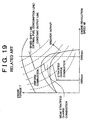
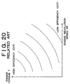
- speed shift lines of the continuously variable transmission are set so as to conform to optimal fuel economy lines (FIG. 19) based on the efficiency of the internal combustion engine, or to optimal fuel economy lines (comparative examples indicated by one-dot chain lines in FIGS. 12 and 15) determined with the efficiency of the internal combustion engine and the efficiency of the continuously variable transmission (FIG. 20) taken into consideration.
- the fuel economy has not been sufficiently improved in a practical region.
- a reason for the insufficient improvement is as follows. Based on the speed shift lines set so as to conform to optimal fuel economy lines as described above, the running of the vehicle in a practical region involves a fuel consumption increase corresponding to the inertia torques caused by fluctuated rotations of an input shaft of the continuously variable transmission, so that a low efficiency results as a whole.
- a drive power control apparatus of a vehicle that is driven by the output of an engine via a transmission determines a target drive power based on a state of operation of the vehicle, and controls the torque of the engine and the speed ratio of the transmission so as to provide an output of the engine for achieving the target drive power.
- the control apparatus controls the speed ratio of the transmission based on a speed shift line that is plotted on a graph having a pair of axis defining the revolution speed of the engine and the torque of the engine so that, within a practical region, the speed shift line is at a low revolution speed side of an optimal fuel consumption line that is determined based on at least the efficiency of the engine and the efficiency of the transmission, of the efficiency of a drive system that includes the engine and the transmission.
- the speed ratio of the transmission is controlled in accordance with the speed shift line that is set so that, within the practical region, the speed shift line is located on the low revolution speed side of the optimal fuel consumption line determined based on the efficiencies of the engine and the transmission of the drive system.
- the speed shift line is shifted to the low engine speed side within the practical region. Therefore, the width of increase in engine revolution speed from the level occurring at the beginning of the practical region is curbed.
- the fuel consumption resulting from inertia torques caused by fluctuations in the engine revolution speed that is, fluctuations in the revolution speed of the input shaft of the transmission, is reduced, so that the efficiency as a whole increases and the fuel economy improves in comparison with the case where the optimal fuel consumption line is used as a control basis.
- the speed shift line may be set so that, within the practical region, a difference between a minimum revolution speed and a maximum revolution speed on the speed shift line is smaller than a difference between a minimum revolution speed and a maximum revolution speed on the optimal fuel consumption line. Furthermore, the speed shift line may be set so that, within the practical region, a sensitivity of a fluctuation in the revolution speed with respect to a fluctuation in the target drive power on the speed shift line is lower than a sensitivity of a fluctuation in the revolution speed with respect to the fluctuation in the target drive power on the optimal fuel consumption line.
- the aforementioned construction prevents great fluctuations in the revolution speed of the engine even if the output of the engine fluctuates in accordance with the target drive power within the practical region. Therefore, the fuel consumption resulting from inertia torques caused by fluctuations in the engine revolution speed, that is, fluctuations in the revolution speed of the input shaft of the transmission, is reduced, so that the efficiency as a whole increases and the fuel economy improves in comparison with the case where the optimal fuel consumption line is used as a control basis.
- the drive power control apparatus may further have a construction wherein the engine comprises a NOx storage-reduction type catalyst in an exhaust system, and during the lean combustion, the engine reduces NOx stored in the NOx storage-reduction type catalyst by performing a rich spike control of temporarily changing an air-fuel mixture so that a fuel concentration in the mixture becomes higher than the fuel concentration corresponding to a stoichiometric air-fuel ratio, and wherein on a boundary line between the lean combustion and the stoichiometric air-fuel ratio combustion in the two-dimensional space of the revolution speed of the engine and the torque of the engine, the speed shift line passes through or near a point at which a corrected fuel consumption rate determined by considering the rich spike control and a fuel consumption rate provided during the lean combustion becomes equal to or closest to a fuel consumption rate provided during the stoichiometric air-fuel ratio combustion.
- the speed shift line is set so that the point which exists on the boundary line between the lean combustion and the stoichiometric air-fuel ratio combustion and through which the speed shift line passes coincides with or exists near the point at which the corrected fuel consumption rate determined by considering the rich spike control and the fuel consumption rate provided during the lean combustion becomes equal to or closest to the fuel consumption rate provided during the stoichiometric air-fuel ratio combustion.
- a target output of the engine for achieving a target drive power set based on a state of operation of the vehicle is calculated. Furthermore, a target revolution speed of the engine is set based on a speed shift line that is plotted on a graph having a pair of axis defining a revolution speed of the engine and the target output of the engine so that, within a practical region in which the state of operation of the engine is practical, a width of increase in the revolution speed of the engine to a relatively high revolution speed on the speed shift line is curbed compared with an optimal fuel consumption line determined based on at least an efficiency of the engine and an efficiency of the transmission, of an efficiency of a drive system that includes the engine and the transmission. Then, the speed ratio of the transmission is controlled so that an actual revolution speed of the engine becomes equal to the target revolution speed.
- the fuel consumption resulting from inertia torques caused by fluctuations in the engine revolution speed that is, fluctuations in the revolution speed of the input shaft of the transmission, is reduced, so that the efficiency as a whole increases and the fuel economy improves in comparison with the case where the optimal fuel consumption line is used as a control basis.
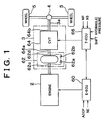
- FIG. 1 is a schematic block diagram of a drive system and a control system for a motor vehicle to which the invention is applied.
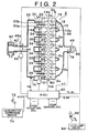
- FIG. 2 schematically shows a construction of the engine 2.
- the engine 2 is a direct injection type gasoline engine that is installed as a vehicle-driving engine in a motor vehicle.
- the engine 2 has six cylinders 2a. As shown in FIGS. 3 to 6, each cylinder 2a has a combustion chamber 10 that is defined by a cylinder block 6, a piston 7 disposed for reciprocating movements within the cylinder block 6, and a cylinder head 8 mounted on the cylinder block 6.
- Each combustion chamber 10 is provided with a first intake valve 12a, a second intake valve 12b, and a pair of exhaust valves 16.
- the first intake valve 12a is connected to a first intake port 14a.
- the second intake valve 12b is connected to a second intake port 14b.
- the two exhaust valves 16 are connected to two exhaust ports 18, respectively.
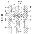
- FIG. 3 is a horizontal sectional view of a portion of the cylinder head 8 corresponding to one of the cylinders.
- the first intake port 14a and the second intake port 14b of each cylinder are straight intake ports that extend substantially linearly.
- An ignition plug 20 is disposed in a central portion of an inner wall surface of the cylinder head 8.
- a fuel injection valve 22 is disposed in a peripheral portion of an inner wall surface of the cylinder head 8 that is adjacent to both the first intake valve 12a and the second intake valve 12b. Each fuel injection valve 22 is disposed so that fuel can be injected therefrom directly into the combustion chamber 10.
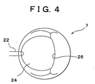
- FIG. 4 is a plan view of a stop surface of one of the pistons 7.
- FIG. 5 is a section taken on line V-V in FIG. 3.
- FIG. 6 is a section taken on line VI-VI in FIG. 3.
- a generally ridge-shaped top face of the piston 7 has a recess 24 having an inverted dome-like contour which extends from a site below the fuel injection valve 22 to a site below the ignition plug 20.
- the first intake ports 14a of the cylinders 2a are connected to a surge tank 32 via first intake passages 30a formed in an intake manifold 30.
- the second intake ports 14b are connected to the surge tank 32 via second intake passages 30b.
- An airflow control valve 34 is disposed within each second intake passage 30b.
- the airflow control valves 34 are interconnected via a common shaft 36, and are opened and closed via the shaft 36 by a negative pressure actuator 37. When the airflow control valves 34 are closed, intake air is introduced via only the first intake ports 14a, and form strong swirls S (FIG. 3) within the combustion chambers 10.
- the surge tank 32 is connected to an air cleaner 42 via an intake duct 40.
- a throttle valve 46 driven by an electric motor 44 (a DC motor or a stepping motor) is disposed in the intake duct 40.
- the degree of opening of the throttle valve 46 (degree of throttle opening TA) and the completely closed state of the throttle valve 46 (complete closure signal IDL) are detected by a throttle opening sensor 46a.
- the degree of opening of the throttle valve 46 is controlled in accordance with the state of operation.
- the exhaust ports 18 of the cylinders 2a are connected to an exhaust manifold 48.
- the exhaust manifold 48 discharges exhaust gas, via a catalytic converter 49 that controls the emission.
- E-ECU engine-controlling electronic control unit
- the E-ECU 60 receives inputs of signals and detected values corresponding to the engine revolution speed NE, the accelerator operation amount ACCP, etc., so as to control the engine 2.
- the transmission mechanism 3 has a fluidic power transfer mechanism 62 and a continuously variable transmission (hereinafter, referred to as "CVT") 64.
- the fluidic power transfer mechanism 62 is a mechanism that transfers torque between the side of an input shaft 62c and the side of an output shaft 62d via a fluid such as an oil or the like.
- the fluidic power transfer mechanism 62 is a torque converter.
- the fluidic power transfer mechanism 62 has a lockup mechanism 62a.
- the lockup mechanism 62a is a clutch mechanism that directly interlocks the input shaft 62c side and the output shaft 62d side via a mechanical means such as a friction plate or the like.
- the lockup mechanism 62a has, for a buffering purpose, a damper 62b that is formed by an elastic body such as coil spring or the like.
- the input shaft 62c of the fluidic power transfer mechanism 62 is connected to a crankshaft of the engine 2.
- the output shaft 62d of the fluidic power transfer mechanism 62 is connected to an input shaft 64a of the CVT 64.
- the CVT 64 is a transmission mechanism capable of steplessly (continuously) varying the ratio between the rotation speed of the input shaft 64a and the rotation speed of an output shaft 64b, that is, the speed ratio.
- the CVT 64 is a belt type continuously variable transmission.
- the CVT 64 incorporates a gear transmission mechanism for accomplishing a reverse drive function, and may further incorporate a gear transmission mechanism for expanding the width of speed ratio if necessary.
- a control of the changing between engagement (locked-up state) and disengagement (unlocked state) of the lockup mechanism 62a of the transmission mechanism 3, and a control of the speed ratio of the CVT 64 are performed by a transmission mechanism-controlling electronic control unit (hereinafter, referred to as "T-ECU") 66 in accordance with the state of running of the vehicle.
- T-ECU transmission mechanism-controlling electronic control unit
- the T-ECU 66 is connected to the E-ECU 60 in a data transmission capable manner, and receives inputs of signals and detected values corresponding to the hydraulic pressure for driving the lockup mechanism 62a, the rotation speeds NP, NS of pulleys of the CVT 64, etc., as data for control.
- the T-ECU 66 also receives inputs of shift signals for selecting one of states of the CVT 64, that is, a stopped state (parking P), a reverse drive state (reverse R), a neutral state (neutral N), an automatic transmission mode (drive D) that is an automatic forward drive state in which the speed ratio is automatically set in accordance with the state of running of the vehicle, and a manual transmission mode (manual M) that is a manual sate in which the transmission state is manually set.
- the E-ECU 60 is a control unit for controlling the engine 2, for example, performing a throttle opening degree control, a fuel injection control, an ignition timing control, an idle speed control, etc.
- the E-ECU 60 is formed as a logic circuit having a CPU 60a, a ROM 60b, a RAM 60c, a backup RAM 60d, etc.
- the ROM 60b is a memory that pre-stores various control programs, data, such as map or the like, for reference during execution of the various programs. Based on the various programs and data stored in the ROM 60b, the CPU 60a executes various operations.
- the RAM 60c is a memory for temporarily storing results of operations of the CPU 60a, data or the like obtained from outputs of various sensors.
- the backup RAM 60d is a non-volatile memory for storing data that needs to be retained during stop of the engine 2.
- the CPU 60a, the ROM 60b, the RAM 60c and the backup RAM 60d are interconnected by a bus 60e, and are also connected to an external input circuit 60f and an external output circuit 60g via the bus 60e.
- the external input circuit 60f is connected to a vehicle speed sensor 68 for detecting the vehicle speed V, an engine speed sensor 70 for detecting the engine revolution speed NE, the throttle opening sensor 46a, an accelerator depression sensor 74 for detecting the accelerator operation amount ACCP, that is, the amount of depression of an accelerator pedal 72, an intake pressure senor 76 for detecting the intake pressure PM in the surge tank 32, an air-fuel ratio sensor 78 for detecting the air-fuel ratio A/F based on exhaust components, a water temperature sensor 80 for detecting the cooling water temperature THW of the engine 2, a stop lamp switch 84 for detecting whether a brake pedal 82 (FIG. 2) has been depressed, etc.
- the external output circuit 60g is connected to the throttle valve-driving motor 44, the fuel injection valve 22 of each cylinder of the engine 2, the negative pressure actuator 37, an igniter (not shown), and other actuators, which are driven when necessary.
- the T-ECU 66 is a control unit that performs an automatic transmission operation by controlling the lockup mechanism 62a and the CVT 64.
- the T-ECU 66 is formed as a logic circuit having a CPU 66a, a ROM 66b, a RAM 66c, a backup RAM 66d, a bus 66e, an external input circuit 66f, an external output circuit 66g, etc. These components 66a to 66g perform basically the same functions as those in the E-ECU 60.
- the external input circuit 66f is connected to a shift device 88 that outputs the aforementioned shift signal SHFT, a primary pulley rotation sensor 89a for detecting the rotation speed NP of the primary pulley in the CVT 64, a secondary pulley rotation sensor 89b for detecting the rotation speed NS of the secondary pulley in the CVT 64, a hydraulic pressure sensor 90 for detecting the hydraulic pressure for driving the lockup mechanism 62a, and other sensors and the like.
- the external output circuit 66g is connected to a speed shift actuator 92 for changing the speed ratio by driving the primary pulley and the second pulley in the CVT 64, a lockup actuator 94 for switching the lockup mechanism 62a of the fluidic power transfer mechanism 62, and other actuators and the like.
- the T-ECU 66 is connected in terms of signals to the E-ECU 60 via the external input circuit 66f and the external output circuit 66g, for mutual communications with the E-ECU 60.
- the E-ECU 60 and the T-ECU 66 constructed as described above perform a coordinate control so as to generate an appropriate drive power on the drive wheels 5 in accordance with a drive power requested by an operating person via the accelerator pedal 72 or the like. More specifically, the E-ECU 60 adjusts one or more of the amount of intake air, the amount of fuel injection, and the form of combustion so as to provide the fuel economy and the engine output torque needed to achieve the requested drive power.
- the T-ECU 66 adjusts the speed ratio so as to achieve an engine revolution speed NE that is needed to achieve a requested drive power.
- one of a stratified charge combustion a uniform combustion and a weak stratified charge combustion is selected in accordance with the state of operation.
- fuel is injected into each combustion chamber 10 from the corresponding fuel injection valve 22 during a late period in the compression stroke so that a stratified mixture with high fuel concentration is formed, and is ignited.
- fuel is injected into each combustion chamber 10 from the corresponding fuel injection valve 22 during the intake stroke so that a uniform mixture is formed, and is then ignited.
- the weak stratified charge combustion fuel is injected both during the intake stroke and during a late period in the compression stroke so that a stratified mixture is formed in a uniform and lean mixture, and is ignited.
- FIG. 9 indicates regions of the forms of combustion that are expressed in a two-dimensional space based on the engine revolution speed NE and the engine torque T.
- broken lines represent constant output lines, and a bent solid line represents a speed shift line CV used in Embodiment 1.
- injected fuel provided by injection performed during the late period of the compression stroke moves from the fuel injection valve 22 into the recess 24 of the piston 7 in each cylinder, and then strikes a peripheral wall surface 26 (see, e.g., FIGS. 4, 5).
- a peripheral wall surface 26 see, e.g., FIGS. 4, 5.
- fuel moves while vaporizing, and forms a combustible mixture layer in the recess 24 adjacent to the ignition plug 20.
- the stratified combustible mixture is ignited by the ignition plug 20, thereby accomplishing stratified charge combustion. In this manner, stable combustion can be accomplished in each combustion chamber 10 with intake air existing in an extremely excess amount relative to fuel.
- an amount of fuel corrected in various manners based on a stoichiometric air-fuel ratio basic fuel injection amount QBS is injected during the intake stroke.
- the injected fuel flows into each combustion chamber 10 together with inflowing intake air, and continues flowing until ignition. Therefore, a uniform mixture of the stoichiometric air-fuel ratio (in some cases, the air-fuel ratio is controlled to a rich air-fuel ratio that means a higher fuel concentration than the stoichiometric air-fuel ratio, due to an increasing correction) is formed in the entire combustion chamber 10, so that the uniform combustion is accomplished.
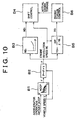
- B 1 to B6 parenthesized represent blocks shown in FIG. 10.
- the blocks B3, B4 correspond to processes performed by the T-ECU 66.
- the other blocks correspond to processes performed by the E-ECU 60.
- a target drive power F is set based on the accelerator operation amount ACCP and the vehicle speed V (B1).
- the vehicle speed V may be substituted with, for example, the rotation speed of a different rotating member that has a corresponding relation with the vehicle speed.
- the setting of the target drive power F based on the accelerator operation amount ACCP and the vehicle speed V is performed based on a map pre-stored in the ROM 60b. More specifically, a relationship between the vehicle speed V and the target drive power F is pre-set as a map using the accelerator operation amount ACCP as a parameter. This map is used. In the setting of the map, the target drive power F is determined so as to reflect characteristics of the object vehicle or engine 2 or the like.
- a target output P is calculated (B2). More specifically, the target output P can be calculated as a product of the target drive power F and the vehicle speed V as in Equation (1). P ⁇ F ⁇ V
- the thus-calculated target output P is used to calculate a target engine revolution speed NEt (B3).
- a target engine revolution speed NEt is calculated from the target output P, with reference to a one-dimensional map as indicated by a solid line in FIG. 11 which is pre-stored in the ROM 66b of the T-ECU 66. If a speed shift line CV is set in a two-dimensional space of the engine revolution speed NE and the engine torque T as indicated in FIG. 9, an engine revolution speed NE can be independently determined in accordance with the output. Therefore, a one-dimensional map for determining the target engine revolution speed NEt by using the target output P as a parameter as indicated by the solid line in FIG. 11 can be set from the speed shift line CV shown in FIG. 9.
- the engine revolution speed NE and the primary pulley rotation speed NP have a relationship of equivalence. Therefore, in the aforementioned speed shift control of the CVT 64, the CVT 64 can be controlled by using the primary pulley rotation speed NP instead of the engine revolution speed NE.
- the blocks B3, B4 are processes performed by the T-ECU 66. In reality, therefore, the T-ECU 66 may control the CVT 64 by handling the target primary pulley rotation speed NPt for the target engine revolution speed NEt, and handling the actual primary pulley rotation speed NP for the actual engine revolution speed NE.
- a target engine torque T0 is calculated from the target output P calculated in the block B2 (B5). More specifically, the target engine torque T0 is calculated by dividing the target output P by the present actual engine revolution speed NE as in Equation (2).
- target engine torque T0 may also be calculated by using the aforementioned target engine revolution speed NEt (target primary pulley rotation speed NPt). T0 ⁇ 30•P/( ⁇ •NE)
- the engine torque is controlled so that the actual engine torque reaches the calculated target engine torque T0 (B6). More specifically, the amount of fuel injection and the amount of intake air are adjusted so that the target engine torque T0 is reached. If the present form of combustion is the stratified charge combustion or the weak stratified charge combustion, the engine torque is adjusted based on the amount of fuel injected. If the present form of combustion is the uniform combustion, the engine torque is adjusted based on the amount of intake air, that is, the degree of opening of the throttle valve 46 (degree of throttle opening TA).
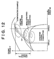
- FIG. 12 Relationships between the speed shift line CV and the fuel consumption rates provided by the forms of combustion is indicated in FIG. 12.
- elliptical broken lines represent constant fuel consumption rate lines.
- a comparative example indicated by one-dot chain lines in FIGS. 11 and 12 represents a case in which an optimal fuel consumption line determined based on the efficiency of the engine 2 and the efficiency of the CVT 64 is set as a speed shift line.
- the speed shift line CV of Embodiment 1 is set on a low engine speed side of the optimal fuel consumption line, as far as a practical region is concerned.
- the speed shift line CV is set so that, within the practical region, the difference between the minimum engine revolution speed NEmin and the maximum engine revolution speed NEmax on the speed shift line CV is smaller than the difference between the minimum engine revolution speed on the optimal fuel consumption line (equal to NEmin) and the maximum engine revolution speed NEZ on the optimal fuel consumption line. Still further, the speed shift line CV is set so that, within the practical region, the sensitivity of revolution speed fluctuation with respect to fluctuation in the target drive power F based on the speed shift line CV is lower than the sensitivity based on optimal fuel consumption line.
- Embodiment 1 constructed as described above achieves the following advantages.
- the speed ratio of the CVT 64 is controlled in accordance with the speed shift line (solid line) that is set so that, within the practical region, the speed shift line is located on the low engine speed side of the optimal fuel consumption line (one-dot chain line) determined based on the efficiency of the engine 2 and the efficiency of the CVT 64. Therefore, the width of increase in the engine revolution speed from the level at the beginning of the practical region is curbed.
- the difference between the maximum engine revolution speed NEmax and the minimum engine revolution speed NEmin on the speed shift line is smaller than the difference between the maximum engine revolution speed NEZ and the minimum engine revolution speed (equal to NEmin) on the optimal fuel consumption line. Therefore, great fluctuations in the engine revolution speed NE of the engine 2 are substantially prevented even if the target drive power F fluctuates in the practical region.
- the fuel consumption resulting from inertia torques caused by fluctuations in the revolution speed of the engine 2, that is, revolution speed fluctuations of the input shaft of the CVT 64 and the input shaft of the fluidic power transfer mechanism 62, is reduced, so that the efficiency as a whole increases and the fuel economy improves in comparison with the case where the optimal fuel consumption line is used as a control basis.
- the speed shift line is set so that the rising of target engine revolution speed NEt is delayed with respect to the rising of the target output P of the engine 2. That is, the speed shift line is set so that, in the practical region, the sensitivity of fluctuation in engine revolution speed with respect to fluctuation in the target drive power F based on the speed shift line is lower than the sensitivity based on the optimal fuel consumption line. Therefore, great fluctuations in the engine revolution speed NE are prevented even if the target drive power F fluctuates in the practical region.
- the speed shift line CV in Embodiment 1 is set so as to define a relationship in which in all the forms of combustion, as the engine torque T increases, the engine revolution speed NE remains constant or increases. Therefore, even in a portion of the practical region, a great fluctuation in the engine speed in response to a small fluctuation in the target drive power F is prevented, so that the aforementioned fuel efficiency improvement becomes more remarkable.
- Embodiment 2 of the invention will next be described.
- Embodiment 2 a NOx storage-reduction type catalyst 99 is incorporated in a catalytic converter 49 shown in FIG. 2, which shows Embodiment 1.
- the E-ECU 60 performs a rich spike control by performing a fuel injection amount control process illustrated in the flowchart of FIG. 13 and a process of setting a rich spike execution flag Fnox illustrated in the flowchart of FIG. 14.
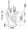
- a speed shift line CV is set as indicted in FIG. 15.
- Other constructions of Embodiment 2 are substantially the same as those of Embodiment 1.
- the hardware construction of Embodiment 2 should be apparent from the aforementioned drawings of Embodiment 1 and the reference characters representing the component parts and the like.
- the fuel injection amount control process will be described with reference to FIG. 13. This process is cyclically executed by every pre-set crank angle.
- the E-ECU 60 inputs various engine operation state data, such as the accelerator operation amount ACCP, the engine revolution speed NE, the intake pressure PM, the cooling water temperature THW, the air-fuel ratio A/F, etc., into work areas in the RAM 60c (S110).
- various engine operation state data such as the accelerator operation amount ACCP, the engine revolution speed NE, the intake pressure PM, the cooling water temperature THW, the air-fuel ratio A/F, etc.
- A/F 11.5
- the E-ECU 60 temporarily ends the process.
- the rich spike execution flag Fnox setting process will be described with reference to the flowchart of FIG. 14.
- the rich spike execution flag Fnox setting process is cyclically executed at every pre-set crank angle.
- the E-ECU 60 determines whether the lean combustion (the stratified charge combustion or the weak stratified charge combustion) is being performed (S210). If the lean combustion is being performed ("YES" in S210), the E-ECU 60 calculates an added amount of NOx that is produced by the lean combustion and is stored into the NOx storage-reduction type catalyst 99, based on the relationship between the intake pressure PM and the amount of fuel injected from each fuel injection valve 22 by the fuel injection amount control process. The E-ECU 60 then increases the amount of NOx stored sNOx calculated in the previous control cycle by the added amount of NOx to determine a new amount of NOx stored sNOx (S220).
- the E-ECU 60 determines whether the amount of NOx stored sNOx has exceeded an allowable storage value NOxCAP (S230). If sNOx ⁇ NOxCAP ("NO" in S230), the E-ECU 60 temporarily ends the process without performing any further processing.
- the E-ECU 60 subsequently sets "ON" in the rich spike execution flag Fnox (S240). Then, the E-ECU 60 temporarily ends the process.
- the E-ECU 60 calculates an amount of NOx that is reduced by unburned gas after being stored in the NOx storage-reduction type catalyst 99, based on the relationship between the intake pressure PM and the amount of fuel injected from each fuel injection valve 22 by the fuel injection amount control process. The E-ECU 60 then decreases the amount of NOx stored sNOx calculated during the previous control cycle by the amount of NOx reduced, thereby determining a new amount of NOx stored sNOx (S250).
- the E-ECU 60 determines whether the amount of NOx stored sNOx is at most "0" (S260). If sNOx ⁇ 0 ("YES" in S260), the E-ECU 60 sets "0" as the amount of NOx stored sNOx (S270), and then sets "OFF" in the rich spike execution flag Fnox (S280). Subsequently, the E-ECU 60 temporarily ends the process. If sNOx > 0 ("NO" in S260), the E-ECU 60 temporarily ends the process without performing any further processing.
- the speed shift line CV is set so that, within the practical region, the speed shift line CV is located on the low engine speed side of the optimal fuel consumption line determined based on the efficiency of the engine 2 and the efficiency of the CVT 64.
- the speed shift line CV is set in the aforementioned setting so as to pass through the point of equality C2 of fuel consumption rate on a boundary line B between the uniform combustion and the weak stratified charge combustion.
- a speed shift line CV is set so as to pass through a point at which the fuel consumption rate in the uniform combustion and the fuel consumption rate in the weak stratified charge combustion are closest to each other, or is set so as to cross on the boundary line B between the uniform combustion and the weak stratified charge combustion, in the vicinity of the point of equality C2 or in the vicinity of the point of greatest proximity.
- Embodiment 2 constructed as described above, achieves substantially the same advantages as those of Embodiment 1.
- the point which exists on the boundary line B between the stratified charge combustion and the uniform combustion and through which the speed shift line CV passes is set to a point of equality or greatest proximity between the fuel consumption rate in the uniform combustion and the corrected fuel consumption rate determined by taking into account the rich spike control as well as the fuel consumption rate in the weak stratified charge combustion, or is set in the vicinity of the point of equality or greatest proximity.
- a fuel consumption rate line with good fuel consumption rate can be obtained by setting the speed shift line CV so as to extend through the point C2 in a region where the form of combustion is switched from the stratified charge combustion to the uniform combustion. Therefore, it becomes possible to change the speed ratio while always maintaining good fuel consumption rate. As a result, fuel economy can be improved.
- the speed shift line CV is a sharply bent line
- the speed shift line CV may also be a line that curves and extends toward the low engine speed side in the practical region. See, e.g., FIG. 17.
- the CVT 64 is a belt type continuously variable transmission
- the CVT 64 may also be a toroidal type continuously variable transmission or the like.
- the lean combustion is performed in the form of the stratified charge combustion or the weak stratified charge combustion.
- the lean combustion may also be performed in other forms, for example, in the form of generally termed "lean burn", that is, a uniform lean combustion in which fuel is uniformly mixed with intake air at a ratio that is on the lean side of the stoichiometric air-fuel ratio and such a uniform mixture is ignited.
- the speed shift line CV is a speed shift line CV for a motor vehicle in which a direct injection type gasoline engine is installed and the form of combustion in the engine is changed.
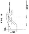
- the speed shift line CV in the invention is also applicable to a speed shift line CV for a motor vehicle in which an intake port injection type engine is installed and the possible form of combustion is only the uniform combustion at the stoichiometric air-fuel ratio as indicated in FIG. 18.
- engine revolution speed fluctuation is reduced, so that the fuel consumption caused by inertia torques is reduced.
- the efficiency as a whole increases and fuel economy improves in comparison with the case where the optimal fuel consumption rate line is used as a control basis.
- a vehicle drive power control apparatus which determines a target drive power based on a state of operation of the vehicle, and which controls the torque of the engine and the speed ratio of the continuously variable transmission so as to provide an output of the engine for achieving the target drive power
- the drive power control apparatus including a controller that controls the speed ratio of the continuously variable transmission in accordance with a speed shift line that is set in a two-dimensional space of the revolution speed of the engine and the torque of the engine. The speed is possible to set in the following way.
- the speed shift line is, with a practical region, at a low revolution speed side of an optimal fuel consumption line that is determined based on an efficiency of the entire drive system that includes the engine and the continuously variable transmission.
- the difference between the minimum revolution speed and the maximum revolution speed on the speed shift line is, with a practical region, smaller than the difference between the minimum revolution speed and the maximum revolution speed on an optimal fuel consumption rate line that is determined based on the efficiency of the entire drive system that includes the engine and the continuously variable transmission.
- the sensitivity of revolution speed fluctuation with respect to fluctuation in the target drive power is, with a practical region, lower on the speed shift line than on an optimal fuel consumption line determined based on the efficiency of the entire drive system that includes the engine and the continuously variable transmission.
- the T-ECU 66 and the E-ECU 60 are implemented as a programmed general purpose computer.
- the controller can be implemented using a single special purpose integrated circuit (e.g., ASIC) having a main or central processor section for overall, system-level control, and separate sections dedicated to performing various different specific computations, functions and other processes under control of the central processor section.
- the controller can be a plurality of separate dedicated or programmable integrated or other electronic circuits or devices (e.g., hardwired electronic or logic circuits such as discrete element circuits, or programmable logic devices such as PLDs, PLAs, PALs or the like).
- the controller can be implemented using a suitably programmed general purpose computer, e.g., a microprocessor, microcontroller or other processor device (CPU or MPU), either alone or in conjunction with one or more peripheral (e.g., integrated circuit) data and signal processing devices.
- a suitably programmed general purpose computer e.g., a microprocessor, microcontroller or other processor device (CPU or MPU)
- CPU or MPU processor device
- peripheral e.g., integrated circuit
- a distributed processing architecture can be used for maximum data/signal processing capability and speed.
Landscapes
- Engineering & Computer Science (AREA)
- Mechanical Engineering (AREA)
- Chemical & Material Sciences (AREA)
- Combustion & Propulsion (AREA)
- General Engineering & Computer Science (AREA)
- Transportation (AREA)
- Automation & Control Theory (AREA)
- Control Of Transmission Device (AREA)
- Control Of Vehicle Engines Or Engines For Specific Uses (AREA)
- Control Of Driving Devices And Active Controlling Of Vehicle (AREA)
- Exhaust Gas After Treatment (AREA)
- Electrical Control Of Air Or Fuel Supplied To Internal-Combustion Engine (AREA)
Abstract
Description
Claims (18)
- A drive power control apparatus of a vehicle providing with an engine (2) that generates a drive power of the vehicle and a transmission (3) that is connected to an output shaft of the engine (2) and that performs a speed shift of the vehicle, determining a target drive power based on a state of operation of the vehicle and controlling a torque of the engine (2) and a speed ratio of the transmission (3) so as to achieve the target drive power, the apparatus characterized and controlling in that:
the speed ratio of the transmission (3) is controlled based on a speed shift line (CV) that is plotted on a graph having a pair of axes defining a revolution speed of the engine (2) and the torque of the engine (2) so that, within a practical region in which the state of operation of the engine (2) is practical, the speed shift line (CV) is at a low revolution speed side of an optimal fuel consumption line that is determined based on at least an efficiency of the engine (2) and an efficiency of the transmission (3), of an efficiency of a drive system that includes the engine (2) and the transmission (3). - A drive power control apparatus of a vehicle providing with an engine (2) that generates a drive power of the vehicle and a transmission (3) that is connected to an output shaft of the engine (2) and that performs a speed shift of the vehicle, characterized in that:a target output of the engine (2) for achieving a target drive power that is set based on a state of operation of the vehicle calculated, anda target revolution speed of the engine (2) is set based on a speed shift line (CV) that is plotted on a graph having a pair of axes defining a revolution speed of the engine (2) and the target output of the engine (2) so that, within a practical region in which the state of operation of the engine (2) is practical, a width of increase in the revolution speed of the engine (2) to a relatively high revolution speed on the speed shift line (CV) is curved compared with an optimal fuel consumption line determined based on at least an efficiency of the engine (2) and an efficiency of the transmission (3), of an efficiency of a drive system that includes the engine (2) and the transmission (3); andthe speed ratio of the transmission (3) is controlled so that an actual revolution speed of the engine (2) becomes equal to the target revolution speed.
- A drive power control apparatus according to claim 1 or 2, characterized in that the speed shift line (CV) is set so that, within the practical region, a difference between a minimum revolution speed and a maximum revolution speed on the speed shift line (CV) is smaller than a difference between a minimum revolution speed and a maximum revolution speed on the optimal fuel consumption line.
- A drive power control apparatus according to claim 1 or 2, characterized in that the speed shift line (CV) is set so that, within the practical region, a sensitivity of a fluctuation in the revolution speed with respect to a fluctuation in the target drive power on the speed shift line (CV) is lower than a sensitivity of a fluctuation in the revolution speed with respect to the fluctuation in the target drive power on the optimal fuel consumption line.
- A drive power control apparatus according to claim 1, characterized in that the speed shift line (CV) is set so that a width of increase in the revolution speed of the engine (2) from a revolution speed occurring at a beginning of the practical region to a relatively high revolution speed is curbed.
- A drive power control apparatus according to any one od claims 1 to 5, characterized in that the internal combustion engine (2) selectively performs at least one form of combustion in accordance with the state of operation, and the optimal fuel consumption line reflects the efficiency of the engine (2) with respect to the at least one form of combustion.
- A drive power control apparatus according to claim 6, characterized in that the at least one form of combustion includes a stoichiometric air-fuel ratio combustion and a lean combustion.
- A drive power control apparatus according to claim 7, characterized in that:the engine (2) comprises a NOx storage-reduction type catalyst in an exhaust system, and during the lean combustion, the engine (2) reduces NOx stored in the NOx storage-reduction type catalyst by performing a rich spike control that temporarily changes an air-fuel mixture so that a fuel concentration in the mixture becomes higher than the fuel concentration corresponding to a stoichiometric air-fuel ratio, andon a boundary line between the lean combustion and the stoichiometric air-fuel ratio combustion in the graph, the speed shift line (CV) passes through or near a point at which a corrected fuel consumption rate determined by considering the rich spike control and a fuel consumption rate provided during the lean combustion becomes equal to or closest to a fuel consumption rate provided during the stoichiometric air-fuel ratio combustion.
- A drive power control apparatus according to any one of claims 1 to 8, characterized in that the speed shift line (CV) is set such that as the torque of the engine (2) increases, the revolution speed of the engine (2) remains constant or increases.
- A drive power control apparatus according to any one of claims 1 to 9, characterized in that the transmission (3) is a continuously variable transmission (3) and the engine (2) is an internal combustion engine (2).
- A drive control method for a vehicle that is driven by an output of an engine (2) via a transmission (3), the method comprising:calculating a target output of the engine (2) for achieving a target drive power that is set based on a state of operation of the vehicle;setting a target revolution speed of the engine (2) based on a speed shift line (CV) that is plotted on graph having a pair of axes defining speed of the engine (2) and the target output of the engine (2) so that, within a practical region in which the state of operation of the engine (2) is practical, a width of increase in the revolution speed of the engine (2) to a relatively high revolution speed on the speed shift line (CV) is curved compared with an optimal fuel consumption line determined based on at least an efficiency of the engine (2) and an efficiency of the transmission (3), of an efficiency of a drive system that includes the engine (2) and the transmission (3); andcontrolling the speed ratio of the transmission (3) so that an actual revolution speed of the engine (2) becomes equal to the target revolution speed.
- A control method according to claim 11, wherein the speed shift line (CV) is set so that, within the practical region, a difference between a minimum revolution speed and a maximum revolution speed on the speed shift line (CV) is smaller than a difference between a minimum revolution speed and a maximum revolution speed on the optimal fuel consumption line.
- A control method according to claim 11, wherein the speed shift line (CV) is set so that, within the practical region, a sensitivity of a fluctuation in the revolution speed with respect to a fluctuation in the target drive power on the speed shift line (CV) is lower than a sensitivity of a fluctuation in the revolution speed with respect to the fluctuation in the target drive power on the optimal fuel consumption line.
- A control method according to claim 11, wherein the speed shift line (CV) is set so that within the practical region, the revolution speed on the speed shift line (CV) is lower than the revolution speed on the optimal fuel consumption line.
- A control method according to any one of claims 11 to 14, characterized in that the engine (2) selectively performs at least one form of combustion in accordance with the state of operation, and the optimal fuel consumption line reflects the efficiency of the engine (2) with respect to the at least one of combustion.
- A control method according to claim 15, characterized in that the at least one form of combustion includes a stoichiometric air-fuel ratio combustion and a lean combustion.
- A control method according to claim 16, wherein:the engine (2) comprises a NOx storage-reduction type catalyst in an exhaust system, and during the lean combustion, the internal combustion engine (2) reduces NOx stored in the NOx storage-reduction type catalyst by performing a rich spike control that temporarily changes an air-fuel mixture so that a fuel concentration in the mixture becomes higher than the fuel concentration corresponding to a stoichiometric air-fuel ratio, andon a boundary line between the lean combustion and the stoichiometric air-fuel ratio combustion in the graph, the speed shift line (CV) passes through or near a point at which a corrected fuel consumption rate determined by considering the rich spike control and a fuel consumption rate provided during the lean combustion becomes equal to or closest to a fuel consumption rate provided during the stoichiometric air-fuel ratio combustion.
- A control method according to any one of claims 11 to 17, characterized in that the transmission (3) is a continuously variable transmission (3) and the engine (2) is an internal combustion engine (2).
Applications Claiming Priority (2)
| Application Number | Priority Date | Filing Date | Title |
|---|---|---|---|
| JP2000151602 | 2000-05-23 | ||
| JP2000151602A JP3882466B2 (en) | 2000-05-23 | 2000-05-23 | Vehicle driving force control device |
Publications (3)
| Publication Number | Publication Date |
|---|---|
| EP1157875A2 true EP1157875A2 (en) | 2001-11-28 |
| EP1157875A3 EP1157875A3 (en) | 2005-11-09 |
| EP1157875B1 EP1157875B1 (en) | 2007-01-03 |
Family
ID=18657133
Family Applications (1)
| Application Number | Title | Priority Date | Filing Date |
|---|---|---|---|
| EP01112468A Expired - Lifetime EP1157875B1 (en) | 2000-05-23 | 2001-05-22 | Vehicle drive power and gearshift control apparatus and control method |
Country Status (5)
| Country | Link |
|---|---|
| US (1) | US6401022B2 (en) |
| EP (1) | EP1157875B1 (en) |
| JP (1) | JP3882466B2 (en) |
| KR (1) | KR100418103B1 (en) |
| DE (1) | DE60125636T2 (en) |
Cited By (3)
| Publication number | Priority date | Publication date | Assignee | Title |
|---|---|---|---|---|
| CN106051140A (en) * | 2015-04-17 | 2016-10-26 | 福特全球技术公司 | Transmission shift schedule optimization based on calculated specific fuel consumption |
| DE102007016618B4 (en) * | 2006-04-07 | 2017-07-13 | Fuji Jukogyo K.K. | Driving force control unit for a vehicle |
| US10626806B2 (en) | 2014-03-21 | 2020-04-21 | Perkins Engines Company Limited | Process and system for controlling engine speed |
Families Citing this family (24)
| Publication number | Priority date | Publication date | Assignee | Title |
|---|---|---|---|---|
| US6932740B2 (en) * | 2000-03-09 | 2005-08-23 | Tci Automotive, Llc | Method for controlling ignition of an internal combustion engine |
| JP4186438B2 (en) * | 2001-07-26 | 2008-11-26 | トヨタ自動車株式会社 | Vehicle control apparatus equipped with continuously variable transmission |
| JP2003058285A (en) * | 2001-08-10 | 2003-02-28 | Fujitsu Ten Ltd | Control system |
| KR100507071B1 (en) * | 2002-06-28 | 2005-08-08 | 현대자동차주식회사 | Acceleration control method for hbrid electric vehicle |
| JP4062264B2 (en) * | 2003-06-06 | 2008-03-19 | アイシン・エィ・ダブリュ株式会社 | Vehicle drive control device, vehicle drive control method, and program |
| US20050040564A1 (en) * | 2003-08-18 | 2005-02-24 | Jones Oliver | Systems and methods for using norbornene based curable materials |
| JP4438574B2 (en) * | 2004-09-01 | 2010-03-24 | トヨタ自動車株式会社 | Control device for vehicle drive device |
| US7832297B2 (en) | 2005-04-19 | 2010-11-16 | Hewatt Chris B | Method and apparatus for gyroscopic propulsion |
| JP4356664B2 (en) * | 2005-08-22 | 2009-11-04 | トヨタ自動車株式会社 | Control device for internal combustion engine |
| US7851695B2 (en) * | 2005-12-26 | 2010-12-14 | Kaneka Corporation | Stacked-type photoelectric conversion device |
| US7684919B2 (en) * | 2006-05-23 | 2010-03-23 | Zf Friedrichshafen Ag | Multiple speed transmission having fuel economy mode |
| JP5264091B2 (en) * | 2007-03-09 | 2013-08-14 | カヤバ工業株式会社 | Automotive throttle throttle control system |
| JP4798108B2 (en) * | 2007-09-25 | 2011-10-19 | トヨタ自動車株式会社 | Control device for internal combustion engine |
| EP2315929A4 (en) | 2008-07-03 | 2013-06-26 | Fuel Saving Technologies Llc | Fuel conservation systems and methods |
| US8639430B2 (en) | 2008-07-03 | 2014-01-28 | Fuel Saving Technologies, Llc | Energy conservation systems and methods |
| US8688337B2 (en) | 2009-04-13 | 2014-04-01 | Toyota Jidosha Kabushiki Kaisha | Driving force control device |
| JP5120323B2 (en) * | 2009-04-14 | 2013-01-16 | 日産自動車株式会社 | Powertrain engine rotation speed control device |
| EP2769071B1 (en) | 2011-10-19 | 2018-08-15 | Fuel Saving Technologies, Inc. | Energy conservation systems and methods |
| JP6019563B2 (en) * | 2011-11-01 | 2016-11-02 | いすゞ自動車株式会社 | Vehicle control device |
| JP5861745B2 (en) * | 2014-06-30 | 2016-02-16 | トヨタ自動車株式会社 | Control device for internal combustion engine |
| US10030594B2 (en) * | 2015-09-18 | 2018-07-24 | Dana Limited | Abuse mode torque limiting control method for a ball-type continuously variable transmission |
| KR102647187B1 (en) | 2016-12-13 | 2024-03-12 | 현대자동차주식회사 | Method and system for controlling torque of hybrid vehicle |
| CN112172824A (en) * | 2020-09-30 | 2021-01-05 | 东风汽车集团有限公司 | A CVT speed ratio control strategy determination method based on vehicle economy |
| CN117823616A (en) * | 2023-09-28 | 2024-04-05 | 浙江万里扬股份有限公司 | A method for determining the parallel speed ratio control strategy of a P2 architecture CVT hybrid transmission |
Citations (2)
| Publication number | Priority date | Publication date | Assignee | Title |
|---|---|---|---|---|
| JPH10329587A (en) | 1997-06-02 | 1998-12-15 | Nissan Motor Co Ltd | Engine combustion mode switching control device for vehicle drive train |
| JPH11198684A (en) | 1998-01-09 | 1999-07-27 | Honda Motor Co Ltd | Vehicle driving force control device |
Family Cites Families (11)
| Publication number | Priority date | Publication date | Assignee | Title |
|---|---|---|---|---|
| US4539643A (en) * | 1981-10-01 | 1985-09-03 | Nissan Motor Company, Limited | Fuel cut-off control system in fuel injection internal combustion engine with automatic power transmission |
| JPS5970849A (en) * | 1982-10-15 | 1984-04-21 | Toyota Motor Corp | Motive power transmission apparatus for car |
| JPS59226748A (en) * | 1983-06-06 | 1984-12-19 | Toyota Motor Corp | Velocity ratio controller of continuously variable transmission for vehicle |
| JPH03189456A (en) * | 1989-12-18 | 1991-08-19 | Mazda Motor Corp | Speed change control device for continuously variable transmission |
| JPH05126239A (en) * | 1991-06-29 | 1993-05-21 | Mazda Motor Corp | Speed change control device of continuously variable transmission for vehicle |
| JP3624331B2 (en) * | 1995-12-18 | 2005-03-02 | 株式会社日立ユニシアオートモティブ | Transmission control device |
| US5850815A (en) * | 1996-04-17 | 1998-12-22 | Honda Giken Kogyo Kabushiki Kaisha | Control system and control process in internal combustion engine |
| JP3211697B2 (en) * | 1997-02-10 | 2001-09-25 | 日産自動車株式会社 | Target transmission ratio generation device for continuously variable transmission |
| JPH1148831A (en) * | 1997-08-01 | 1999-02-23 | Nissan Motor Co Ltd | Vehicle output control device |
| JP3460576B2 (en) * | 1998-04-28 | 2003-10-27 | トヨタ自動車株式会社 | Control device for vehicle with continuously variable transmission |
| US6066070A (en) * | 1998-04-28 | 2000-05-23 | Toyota Jidosha Kabushiki Kaisha | Control system of vehicle having continuously variable transmission |
-
2000
- 2000-05-23 JP JP2000151602A patent/JP3882466B2/en not_active Expired - Fee Related
-
2001
- 2001-05-22 DE DE60125636T patent/DE60125636T2/en not_active Expired - Fee Related
- 2001-05-22 US US09/861,620 patent/US6401022B2/en not_active Expired - Fee Related
- 2001-05-22 KR KR10-2001-0028059A patent/KR100418103B1/en not_active Expired - Fee Related
- 2001-05-22 EP EP01112468A patent/EP1157875B1/en not_active Expired - Lifetime
Patent Citations (2)
| Publication number | Priority date | Publication date | Assignee | Title |
|---|---|---|---|---|
| JPH10329587A (en) | 1997-06-02 | 1998-12-15 | Nissan Motor Co Ltd | Engine combustion mode switching control device for vehicle drive train |
| JPH11198684A (en) | 1998-01-09 | 1999-07-27 | Honda Motor Co Ltd | Vehicle driving force control device |
Cited By (4)
| Publication number | Priority date | Publication date | Assignee | Title |
|---|---|---|---|---|
| DE102007016618B4 (en) * | 2006-04-07 | 2017-07-13 | Fuji Jukogyo K.K. | Driving force control unit for a vehicle |
| US10626806B2 (en) | 2014-03-21 | 2020-04-21 | Perkins Engines Company Limited | Process and system for controlling engine speed |
| CN106051140A (en) * | 2015-04-17 | 2016-10-26 | 福特全球技术公司 | Transmission shift schedule optimization based on calculated specific fuel consumption |
| CN106051140B (en) * | 2015-04-17 | 2019-10-18 | 福特全球技术公司 | Transmission shift schedule optimization based on calculated specific fuel consumption |
Also Published As
| Publication number | Publication date |
|---|---|
| KR100418103B1 (en) | 2004-02-11 |
| EP1157875B1 (en) | 2007-01-03 |
| JP2001328464A (en) | 2001-11-27 |
| JP3882466B2 (en) | 2007-02-14 |
| DE60125636D1 (en) | 2007-02-15 |
| US6401022B2 (en) | 2002-06-04 |
| KR20010107648A (en) | 2001-12-07 |
| US20020014363A1 (en) | 2002-02-07 |
| EP1157875A3 (en) | 2005-11-09 |
| DE60125636T2 (en) | 2007-10-04 |
Similar Documents
| Publication | Publication Date | Title |
|---|---|---|
| EP1157875B1 (en) | Vehicle drive power and gearshift control apparatus and control method | |
| EP1279548B1 (en) | Control system and method for vehicle having continuously variable transmission | |
| US20050171670A1 (en) | Control apparatus and process for internal combustion engine | |
| EP1158152B1 (en) | Fuel supply amount control apparatus and method for internal combustion engine | |
| WO2005103471A1 (en) | Device and method for controlling engine | |
| US8909441B2 (en) | Driving power source rotational speed control device and driving power source rotational speed control method | |
| US4972737A (en) | Control system for engine and transmission using two power modes | |
| JP2000052817A (en) | Vehicle control device | |
| JP2002349688A (en) | Transmission control device | |
| JPS63176635A (en) | Electronic type fuel injection controller | |
| JP3559882B2 (en) | Vehicle output control device | |
| JP3610752B2 (en) | Vehicle output control device | |
| JP2000248972A (en) | Fuel injection control device for internal combustion engine | |
| JP4269956B2 (en) | Control device for internal combustion engine with continuously variable transmission | |
| JP3307015B2 (en) | Integrated control system for lean burn engine and continuously variable transmission | |
| JP2025182670A (en) | Powertrain Control Device | |
| EP1205656A1 (en) | Device and method for engine control | |
| JPH11270390A (en) | Fuel injection control device for internal combustion engine | |
| JP2001039183A (en) | Engine and transmission cooperative control device | |
| JPH06280631A (en) | Air-fuel ratio controller for engine | |
| JP2570376B2 (en) | Integrated control device for automatic transmission and engine | |
| JPH05172236A (en) | Shift control device for automatic transmission | |
| JPH0674319A (en) | Vehicle control device | |
| JPH10203202A (en) | Internal combustion engine torque fluctuation suppression device | |
| JPS6179058A (en) | Method of controlling speed change operation of automatic transmission for vehicle |
Legal Events
| Date | Code | Title | Description |
|---|---|---|---|
| PUAI | Public reference made under article 153(3) epc to a published international application that has entered the european phase |
Free format text: ORIGINAL CODE: 0009012 |
|
| 17P | Request for examination filed |
Effective date: 20010611 |
|
| AK | Designated contracting states |
Kind code of ref document: A2 Designated state(s): AT BE CH CY DE DK ES FI FR GB GR IE IT LI LU MC NL PT SE TR |
|
| AX | Request for extension of the european patent |
Free format text: AL;LT;LV;MK;RO;SI |
|
| PUAL | Search report despatched |
Free format text: ORIGINAL CODE: 0009013 |
|
| AK | Designated contracting states |
Kind code of ref document: A3 Designated state(s): AT BE CH CY DE DK ES FI FR GB GR IE IT LI LU MC NL PT SE TR |
|
| AX | Request for extension of the european patent |
Extension state: AL LT LV MK RO SI |
|
| AKX | Designation fees paid |
Designated state(s): DE FR GB IT |
|
| GRAP | Despatch of communication of intention to grant a patent |
Free format text: ORIGINAL CODE: EPIDOSNIGR1 |
|
| RIC1 | Information provided on ipc code assigned before grant |
Ipc: B60W 10/04 20060101AFI20060725BHEP Ipc: B60W 10/10 20060101ALI20060725BHEP Ipc: F16H 61/04 20060101ALI20060725BHEP Ipc: B60W 30/18 20060101ALI20060725BHEP |
|
| GRAS | Grant fee paid |
Free format text: ORIGINAL CODE: EPIDOSNIGR3 |
|
| GRAA | (expected) grant |
Free format text: ORIGINAL CODE: 0009210 |
|
| RIN1 | Information on inventor provided before grant (corrected) |
Inventor name: ISAO, TAKAGI Inventor name: HIROFUMI, KUBOTA Inventor name: ZENICHIRO, MASHIKI Inventor name: HIROYA, TANAKA Inventor name: SHINICHI, MITANI |
|
| AK | Designated contracting states |
Kind code of ref document: B1 Designated state(s): DE FR GB IT |
|
| REG | Reference to a national code |
Ref country code: GB Ref legal event code: FG4D |
|
| REF | Corresponds to: |
Ref document number: 60125636 Country of ref document: DE Date of ref document: 20070215 Kind code of ref document: P |
|
| ET | Fr: translation filed | ||
| PLBE | No opposition filed within time limit |
Free format text: ORIGINAL CODE: 0009261 |
|
| STAA | Information on the status of an ep patent application or granted ep patent |
Free format text: STATUS: NO OPPOSITION FILED WITHIN TIME LIMIT |
|
| 26N | No opposition filed |
Effective date: 20071005 |
|
| PGFP | Annual fee paid to national office [announced via postgrant information from national office to epo] |
Ref country code: DE Payment date: 20080529 Year of fee payment: 8 |
|
| PGFP | Annual fee paid to national office [announced via postgrant information from national office to epo] |
Ref country code: IT Payment date: 20080527 Year of fee payment: 8 |
|
| PGFP | Annual fee paid to national office [announced via postgrant information from national office to epo] |
Ref country code: GB Payment date: 20080528 Year of fee payment: 8 |
|
| GBPC | Gb: european patent ceased through non-payment of renewal fee |
Effective date: 20090522 |
|
| REG | Reference to a national code |
Ref country code: FR Ref legal event code: ST Effective date: 20100129 |
|
| PG25 | Lapsed in a contracting state [announced via postgrant information from national office to epo] |
Ref country code: FR Free format text: LAPSE BECAUSE OF NON-PAYMENT OF DUE FEES Effective date: 20090602 |
|
| PGFP | Annual fee paid to national office [announced via postgrant information from national office to epo] |
Ref country code: FR Payment date: 20080514 Year of fee payment: 8 |
|
| PG25 | Lapsed in a contracting state [announced via postgrant information from national office to epo] |
Ref country code: GB Free format text: LAPSE BECAUSE OF NON-PAYMENT OF DUE FEES Effective date: 20090522 |
|
| PG25 | Lapsed in a contracting state [announced via postgrant information from national office to epo] |
Ref country code: DE Free format text: LAPSE BECAUSE OF NON-PAYMENT OF DUE FEES Effective date: 20091201 |
|
| PG25 | Lapsed in a contracting state [announced via postgrant information from national office to epo] |
Ref country code: IT Free format text: LAPSE BECAUSE OF NON-PAYMENT OF DUE FEES Effective date: 20090522 |