BACKGROUND OF THE INVENTION
1. Field of the Invention
The present invention relates to electrosurgical generators, and in particular
to an electrosurgical generator with RF leakage reduction.
2. Background Information
The use of RF energy to cut and coagulate tissue during a surgical procedure
is well known. Anytime an electrosurgical generator is activated, varying amounts of
RF leakage are produced. Power setting, RMS (root mean squared) voltages,
accessories and physical layout of the system cause the amount of RF leakage to
vary. All of these variables, when set in the worse case condition, can cause a high
level of RF energy that could cause a patient and/or operating room personnel to
receive an RF bum. (A RF bum is caused by a high current density flowing through
a small amount of tissue area for a relative long period of time in an area that is not
intended to have a clinical affect applied to it). These RF bums can vary from slight
reddening to severe bums requiring surgical intervention..
To address this problem, test agencies have adopted specific tests to
accurately measure the amount of RF leakage produced by an electrosurgical
generator. An example of a test agency that has adopted the RF leakage test is
International Electrotechnical Commission (IEC). IEC 60601-2-2 has defined a test
setup and the maximum amount of RF leakage allowed for this test setup. Under the
prescribed test, the maximum amount of RF leakage is 150 milliamps.
SUMMARY OF THE INVENTION
The electrosurgical generator of the present invention utilizes an isolated
output configuration designed to reduce RF leakage. In addition, the invention
comprises a method for sensing output parameters to reduce RF leakage. Two
separate methods of monitoring the output waveforms are disclosed. The first
method utilizes the output voltage to determine if the generator should operate in a
RF leakage reduction mode or not. If the output voltage applied to the patient is low,
lower than a preset level, then the generator will operate normally. If the output
voltage applied to the patient is higher than the preset level, then the generator will
operate in the leakage reduction mode.
The second method utilizes the output current to determine whether the
generator should operate in the RF leakage reduction mode. If the output current
applied to the patient is low, lower than a preset level, the generator will operate in
the leakage reduction mode. If the output current applied to the patient is higher than
the preset level, then the generator will operate normally.
BRIEF DESCRIPTION OF THE DRAWINGS
Fig. 1 is a schematic diagram illustrating the general functions of an
electrosurgical generator;
Fig. 2 is a load curve graphing output power to output load impedance of the
electrosurgical generator;
Fig. 3 illustrates typical RF logic waveforms;
Fig. 4a illustrates the sensed peak output voltages of the preset levels for the
CUT mode at various power settings;
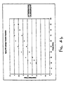
Fig. 4b illustrates the sensed peak output voltages of the preset levels for the
COAG mode at various power settings;
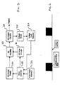
Fig. 5 is a schematic diagram similar to Fig. 1 adding voltage sensing and
peak detecting;
Fig. 6 illustrates the RF drive timing;
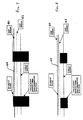
Fig. 7 illustrates an input and output of a peak detector when operating the
generator into an open circuit;
Fig. 8 illustrates a typical input/output of the peak detector when operating the
generator into a loaded condition;
Fig. 9 illustrates a normal operating condition relating to the peak detector
while delivering power to the load;
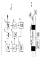
Fig. 10 is a schematic diagram similar to Fig. 1 adding current sensing and
average current detecting;
Fig. 11 is a schematic diagram of a voltage peak detector circuit;
Fig. 11a is a schematic diagram showing the connection of the voltage peak
detector to the output bandpass filter;
Fig. 12 is a schematic diagram of an average current detector circuit;
Fig. 12a is a schematic showing the connection of the average current sense
circuit connected to the output of the generator;and
Fig. 13 illustrates an output of the average current detector circuit.
DESCRIPTION OF THE PREFERRED EMBODIMENT
Before explaining the present invention in detail, it should be noted that the
invention is not limited in its application or use to the details of construction and
arrangement of parts illustrated in the accompanying drawings and description,
because the illustrative embodiments of the invention may be implemented or
incorporated in other embodiments, variations and modifications, and may be
practiced or carried out in various ways. Furthermore, unless otherwise indicated,
the terms and expressions employed herein have been chosen for the purpose of
describing the illustrative embodiments of the present invention for the convenience
of the reader and are not for the purpose of limiting the invention.
I. General Electrosurgical Operation
System Operation
In order to understand the operation of the invention a general description of
the power control system operation of an electrosurgical generator is required. Fig.
1 shows the main functions that describe the operation of the RF Leakage Reduction
Algorithm. Additional block diagram functions are required to explain the complete
operation of an electrosurgical generator but are not included in this disclosure, but
are well known to those skilled in the art.
DC Power Supply
The DC power supply 20 converts AC line voltage to a DC voltage that drives
the RF amplifier 22. The power supply 20 regulates the output current, power and
voltage. (Prior art shows that the same regulation properties can be achieved by a
Pulse Width Modulation (PWM) technique on a RF amplifier. This disclosure does
not use this PWM technique, but the algorithm described within will operate using the
PWM technique). As the RF energy is delivered, the power supply 20 determines the
appropriate regulation mode (current, power or voltage) in which it should operate.
The graph of Fig. 2 provides a better understanding of the regulation modes.
Referring to Fig. 2, constant current occurs at the lower impedances when the
output requires higher current than a pre-set value. The different modes of operation,
such as cut or coagulation, require different constant current limits. As long as the
output impedance is low the DC power supply 20 will regulate to the constant
current. When the output impedance increases, the DC power supply 20 will change
to a constant power regulation. Constant power operates within the medium range
of impedances and limits the output power for each power setting. This constant
power allows the same amount of power to be delivered to the patient as long as the
impedance is within the proper range. As the output impedance continues to
increase, the DC power supply 20 begins to regulate with a constant voltage. The
constant voltage limits the output DC voltage that is delivered to the RF amplifier 22.
In turn, the output power reduces in an inverse relationship (1/Z) to the output
impedance. At the point in which the system changes from one regulation mode to
the next, a "roll-off" point can be defined. For example, if the Cut mode transitions
from the power regulation mode to the voltage regulation mode at 800 ohms, the cut
mode is said to have an upper "roll-off' point of 800 ohms.
RF Amplifier
The RF amplifier 22 converts the DC voltage to a high frequency, energy. Any
type of RF amplifier can be used to create the electrosurgical energy, i.e., Full
Bridge, Single Ended, Push-Pull, etc. By controlling the RF energy, as described in
the DC power supply 20 section and by controlling the output waveform, different
clinical effects are produced. The cut mode is produced by creating a continuous,
approximately 500 kHz RF waveform. Applying a duty cycle to the waveforms
produces Blend (Cutting with Hemostasis), Coagulation (Fulguration and Contact)
and Bipolar Coagulation modes. Different clinical effects can be achieved depending
on the duty cycle and the "roll-off" points of the mode of operation.
RF Output Circuitry
The RF output circuitry 24 begins with the output transformer and ends at the
operating site. All RF amplifiers have an output transformer to convert the low
primary voltage to a higher output voltage. The cut modes require less voltage, but
higher power levels than the coagulation modes. The output transformer steps the
primary voltage to a point where the requirements of the roll-off points at maximum
power settings are met. In the coagulation mode, especially in the Spray or
Fulguration mode, the turns ratio is much higher than in the cut modes. This allows
for a very high voltage level when the generator is operated into a high impedance
in the voltage regulation mode. The high voltage is required for creating and
maintaining arcs to the operating site.
In most cases, the RF output circuitry 24 requires a high frequency filter.
(Many Single Ended type amplifiers operate into a "tune tank", thus producing
sinusoidal waveforms naturally.) The filter coverts the input waveform, basically a
square wave, into a sinusoidal waveform. By converting the output to a sinusoidal
waveform, the problem with RF leakage is reduced. In most cases, however, RF
leakage is still higher than the maximum allowed RF leakage current a specified in
IEC 60601-2-2.
In addition, the RF output circuitry 24 requires relays to direct the RF energy
to the appropriate output accessory and, in turn, to the operative site.
Front Panel Interface
The Front Panel Interface 26 is simply the interface between the operating
room personnel and the generator. The operating room personnel instruct the
generator of the appropriate mode and power setting for the clinical procedure. In
tum, the front panel displays the requested information and provides activation
information to the operating room personnel. In most generators, when the operating
room personnel activate a mode, the front panel initiates an indicator to inform the
user which mode is operated.
Microcontroller
The microcontroller 28 is the heart of the system. (In some simple
electrosurgical generators, a microcontroller is not used. Instead, logic systems are
used to determine the way the system is operating). Its main function is to determine
the system operation depending on the input received. In addition, the
microcontroller 28 monitors the safety features of the system. If a safety system
shows a problem, the microcontroller 28 determines and implements the appropriate
action.
The microcontroller 28 determines the level of DC voltage required to produce
a given mode of operation, RF drive waveforms, "roll-off" points to determine the load
curve, and many other functions of the generator. By using a microcontroller 28,
many functions, input and output, can be conducted simultaneously. For example,
when the generator is activated in the Spray Coag mode, an input to the
microcontroller 28 can monitor the peak voltage of the output waveform. If the output
voltage reaches a pre-determined level the RF drive signal could be modified. By
adjusting the RF drive waveform, different physiological effects can be obtained.
RF Drive & Logic
Electrosurgical generators develop the RF drive signals many different ways.
Some use discrete transistors, some use logic systems, while others use a
combination of microcontroller and logic to determine the RF drive pulses. In all
electrosurgical generators different waveforms are generated for given modes of
operations by the RF drive and logic circuit 30. For example, a pure cut waveform
would have continuous train of pulses delivered to the RF amplifier 22. A coagulation
waveform would have a short duration of pulses (in some cases only one pulse) and
a long duration of off time, which provides high peak energy while producing low
RMS power to the surgical site required for coagulation. The train of pulses will
operate at the operating frequency of the RF amplifier 22. All electrosurgical
generators operate between 300kHz and 5MHz, with the majority operating around
500kHz. Typical RF logic waveforms are shown in Fig. 3.
The RF drive receives pulses from the RF logic and increases the energy
required to operate the RF amplifier 22. For example, the power MOSFETs used in
the RF amplifier 22 requires a switching signal that is positive 15 volts to properly
tum the device on and off. The RF drive and logic circuit 30 produces these required
voltage levels. Many different circuits are well known to properly operate the power
MOSFET transistors inside the RF amplifier.
II. RF Leakage Reduction Algorithm
Voltage Sensing Method
Output Voltage Characteristics
Output voltage varies depending upon the output load characteristics under
which the generator is operating. If the output load impedance is low enough to
operate in the constant current or the constant power portion of the output load
curve, the voltage will remain relatively low. While the generator operates in these
portions of the load curve the power supply 20 will adjust the DC voltage, which in
turn, will adjust the output voltage.
When the load impedance reaches values high enough to operate in the
constant voltage portion of the load curve, the DC power locks into a constant
voltage mode. At this point the output power begins to roll off as shown Fig. 2.
Different modes of operations require different roll off points. For example, the roll off
point for the Cut mode could be around 800 ohms while the Blend mode rolls off at
1500 ohms. The desired clinical effect and the output characteristics of the mode
determine each roll off point.
As the impedance increases beyond the roll off point, the DC power supply
20 remains at the constant voltage but the peak voltage of the output waveform
continues to increase. The increased "Q" of the output filter and the overshoot
characteristics of the pulsed output waveform causes an increase in peak voltage.
The Cut waveform increases only because of the increased "Q" of the output filter
since the Cut mode is not pulsed. Since the higher impedances, greater than
2000, provide a higher "Q" for the output filters the increase in peak voltage is
significant. This large open circuit peak voltage is a strong indicator that the
generator is operating in or close to an open circuit load. This is the worst-case
condition and carries with it an increased risk of a RF bum.
Shown in Fig. 4a and 4b are two graphs that show the sensed output
voltages for the Cut mode and the Spray Coag mode, respectively, in the present
generator. Each graph shows the output voltage of the peak detector (explained
below) for the 2000 ohms load, lower curve, and the open circuit load, upper
curve. It should be noted that the Spray mode exhibits a much higher differential
between the two loads than the Cut mode. This is because the Cut mode is not a
pulsed drive signal and the waveform will increase only as a function of the
increased "Q" of the output filter.
In addition to the actual measured voltages in the Cut mode, the Cut RF
Transfer Function shows the derived mathematical function as determined by a
curve-fitting program. These mathematical functions are used to tell the
microcontroller whether or not to operate in the RF leakage reduction mode.
Although not mandatory, the use of mathematical models does make implementation
into the software much easier. In the case of the Spray mode, "switching steps" can
be used to tell the microcontroller in which mode to operate.
Fig. 5 illustrates the RF leakage topology. The voltage sense 32 and voltage
peak detector 34 circuit blocks were added to the original block diagram of Fig. 1.
To sense the output voltage of the generator, a high frequency, high voltage
sensing method must be employed. Several different methods are available but the
present generator utilizes a high frequency, high voltage sensing transformer 35 to
sense the output voltage. The "turns ratio" used in the sensing transformer is 1:48
for the present generator. This value can easily be adjusted to adapt to different
sensing configurations.
The output voltage sense transformer 35 is applied to a voltage peak detector
34, shown in Fig. 11 and Fig. 11a. The sensing transformer also acts as the parallel
leg of the output filter as shown in Fig. 11a. Peak detectors are used to accurately
sense and hold the measured peak voltage of the output waveform. As the output
voltage pulses are applied to the peak detector, a DC voltage that represents the
highest peak is developed on the output of the detector. In this application the actual
input/output voltage ratio is approximately 1 to 1000. Therefore, a 1-volt DC signal
on the output of the peak detector represents a 1000-volt peak on the output of the
generator.
Application of the Output of the Peak Detector into the Microcontroller
The output voltage of the peak detector is applied to an analog input of the
microcontroller 28. Alternatively, it should be noted that the output of the peak
detector could be applied to an "off-the-shelf" A to D converter. In turn, the output of
the A to D converter is then applied to the digital bus. The microcontroller 28
converts the analog voltage to a digital number that represents the analog voltage.
This digital number is then compared to a reference level set up in the software at
each power setting. If the voltage is greater than the upper level then the
microcontroller 28 will operate in the RF leakage reduction mode. If the voltage is
lower than the lower level then the microcontroller 28 will operate in the normal
mode. By using two reference levels, a hysteresis switching can be established. This
will reduce the tendency for the generator to oscillate between the RF leakage
reduction mode and the normal mode of operation. In some applications this
hysteresis may not be required.
For each mode of operation, different reference tables are used to optimize
switching between the RF leakage reduction mode and the normal mode of
operation. Therefore, each power setting will have the appropriate reference level to
operate properly.
Application of the RF Leakage Reduction Mode on the RF Amplifier Circuitry
When the generator is activated into an open circuit, the peak voltage of the
output waveform increases to a point above the upper reference voltage. For
example, if the generator is operated in the Spray Coag mode at a power setting of
50 watts, the output of the peak detector would read approximately 3.6 volts (see the
Spray Coag RF Leakage Transfer Function in Fig. 4b). If the upper reference voltage
for this power setting is lower than the 3.6 volts, then the microcontroller 28 will
switch the drive for the RF amplifier 22 into the RF leakage reduction mode. In this
mode, the RF Drive and Logic 30 is cycled on and off. An exemplary cycle sequence
is to turn the RF drive "on" for 1 millisecond and then "off" for 4 milliseconds. The one
to four ratio is currently being used in the present generator but other values can be
chosen for different applications such as 1 millisecond "on" and 5 milliseconds "off".
The 1 millisecond "on" time gives the generator ample time to operate and relay the
output conditions back the microcontroller 28. The 4 milliseconds "off" time was
chosen to ensure that RF leakage is reduced to an acceptable level. A drawing of the
RF output waveform driving the RF Amplifier is shown in Fig. 6, wherein the square
wave is representative of a train of RF pulses.
With the drive waveform operating with 1 millisec "on" and 4 millisecs "off", a
20% duty cycle is generated. This 20% duty cycle is, in turn, applied to the output
waveform. As a result, the RMS output waveform is reduced to approximately 20%
of the original 100% on time waveform. Since RF leakage is a function of the RMS
voltage applied to the operating site, an output waveform that has a reduction of the
RMS voltage to 20% of the original RMS voltage, a much lower value of RF leakage
is achieved. As would be apparent to those skilled in the art, the value of RF leakage
might not be 20% of the original RF leakage because of the many variables that
effect RF leakage, but it will be significantly reduced.
Referring to Fig. 7, as long as the generator remains in an open circuit
condition, the peak voltage will remain high enough to keep the DC voltage 44 from
the voltage peak detector 34 higher than the upper threshold 40. The microcontroller
28 will thus keep the generator operating in the RF leakage reduction mode. As soon
as the output is operated into a loaded condition (the active electrode is cutting or
coagulating tissue), the peak voltage will drop below the lower threshold 42 and the
microcontroller 28 will begin to operate the generator in the normal mode.
Continuing the example of the 50-watt setting of the Spray mode, the peak
voltage represented by the voltage peak detector 34 will read approximately 2.6 volts
when the output is delivered into 2000 ohms. This difference between the open
circuit voltage (3.6 volts) and the loaded voltage (2.6 volts) allows for a differential
voltage of approximately 1.0 volts. In order for the microcontroller 28 to operate
properly, thresholds must fall between these two levels. At the 50-watt setting in the
Spray mode, if the upper level is set to 3.0 volts and the lower level is set to 2.9 volts
the microcontroller 28 will properly switch in and out of the RF leakage reduction
mode. Each power setting and mode of operation will require a new set of thresholds
to operate properly.
Input / Output Signals of the Peak Detector
If the voltage peak detector 34 is subjected to an open circuit voltage (while
at a high power setting), the DC voltage presented to the microcontroller 28 will be
higher than a preset voltage. (This voltage may either be one or several fixed
voltages or a formula to represent the threshold voltages.) When the DC voltage
exceeds the preset voltage the microcontroller 28 will begin to deliver bursts of drive
pulses instead of continuous drive pulses. These bursts of RF pulses on the output
will produce a lower RMS voltage while keeping the peak voltage high. The one
millisecond "on time" will allow the generator to produce an arc when the electrode
is close enough to the tissue. In order to reduce the RF leakage to an acceptable
level, the RF drive should be turned off for approximately 4 millisecs. This will
produce a 20% duty cycle. The diagram shown in Fig. 7 shows the input and the
output of the-voltage peak detector 34 while the generator is operating in an open
circuit.
While the generator is operating in the RF leakage reduction mode, the
voltage peak detector 34 continuously monitors the output waveform. If the output
operates in a loaded condition, the peak voltage will drop. The drop in output voltage
is applied to the voltage peak detector 34 and begins to drop the peak detector's
output. The amount of time it takes for the output voltage to decrease below the
lower threshold is defined by the RC time constant of the output circuitry of the peak
detector. The design of the RC time constant will determine the desired clinical
effect. If the time constant is too short, the generator may continuously switch
between the RF leakage reduction mode and the normal mode of operation or it may
switch under a noise pulse. If the time constant is too long a "buzzing" noise may be
heard at the operating site. This will be an annoyance to the operator. Until the
voltage drops below the lower threshold 42, the diagram of Fig. 8 shows the typical
input/output characteristics of the peak detector 34. Since the output peak voltage
is below the output voltage of the peak detector 34, the peak detector 34 will not
"pump-up" the peak detector's output voltage. The microcontroller 28 will continue
to operate the system in the RF leakage reduction mode.
Eventually the peak detector's output voltage will reduce to the point that is
below the lower threshold 42. At that time, the microcontroller 28 will switch the
output characteristics to the normal operating mode of operation, Fig. 9. As long as
the output is operated into low impedances, the generator will remain in this mode
of operation and the output voltage of the peak detector 34 will remain below the
upper threshold. As soon as the generator is operated into an open circuit, the RF
leakage reduction mode will begin to operate once again.
Current Sensing Method
By using current as the sensing variable, the same characteristics for RF
leakage reduction can be achieved. The current sensing method uses either peak
detection or an RMS/Averaging sensing method. For this application it was simpler
to apply the averaging sensing system.
Depending on the output characteristics into which the generator is operating,
the average output current will vary. If the output load impedance is low enough to
operate in the constant current or the constant power portion of the output load curve
the current will remain relatively high. While the generator operates in these portions
of the load curve the power supply 20 will adjust the DC voltage, which in turn, will
adjust the output current.
When the load impedance reaches values high enough to operate in the
constant voltage portion of the load curve, the average output current will be low. As
the load impedance increases to higher impedances, the current continues to
reduce. At an open circuit condition the current reduces close to zero current (the
only current that is produced is a result of the leakage current).
The block diagram shown in Fig. 10 shows the major circuit functions to make
up the current sensing method. Note that the configuration of the blocks is very
similar to the voltage sensing method. The schematic for the average current
detector 52 is shown in Fig. 12.
Application of the RF Leakage Reduction Mode on the RF Amplifier Circuitry
The algorithm for RF leakage reduction is the same as in the voltage mode,
except current is measured and compared against thresholds. Tables contained
within the microcontroller 28 are adjusted for the current sensing system. The rest
of the algorithm remains the same.
Examples of the RF reduction algorithms follow below. The first describes the
system that is currently used in the present generator for the monopolar mode. The
monopolar mode uses the voltage-sensing algorithm. The second describes the
system that is currently used in the present generator for the bipolar mode. The
bipolar mode uses the current-sensing algorithm.
RF Leakage Reduction Algorithm (Monopolar Only)
Referring to Fig. 13, the following is a description of the process how the RF
Leakage Reduction circuitry and software functions in the generator for monopolar
operation.
Basic Operation
RF leakage occurs anytime an electrosurgical generator is operated. The
amount of RF leakage produced by a generator is a function of many factors. IEC
60601-2-2 has defined a test setup and the maximum amount of RF leakage allowed
for this test setup. The generator is an isolated output configuration and is designed
to reduce the RF leakage as much as possible, but because of the high open circuit
voltage the RF leakage is still higher than the IEC limit. This algorithm describes the
method in which the RF leakage reduction will operate.
The way the generator operates, the highest level of RF leakage occurs in the
open circuit mode. This is when the peak voltage and the RMS voltage of the output
waveform are the highest. In order to reduce the RF leakage, the RMS voltage of the
waveform must be reduced to a level that will pass the RF leakage specification. One
method to reduce RF leakage is to lower the DC power supply 20 causing the RMS
voltage to reduce. The peak voltage, however, will also reduce and in turn, the arc
length, especially in the Spray mode, will also reduce. This is not the best way to
solve the RF leakage problem. The disclosed RF leakage reduction algorithm will
reduce the RMS of the waveform while maintaining the same peak voltage. By
keeping the peak voltages high, the arc length will remain the same in the Spray
mode.
A sample of the output voltage is applied to a voltage peak detector 34. In
each mode, the open circuit voltage is significantly higher than the loaded voltage.
When the generator is keyed, the output waveform is sampled and sent to the peak
detection circuitry. This circuit converts the peak voltage to a DC level. The output
capacitor of the peak detector charges quickly but discharges slowly. The rate of
discharge is simply adjusted by the output R and C values. In general, see Fig. 13.
Input / Output Signals of the Peak Detector
If the peak detector is subjected to open circuit voltage (while at a high power
setting), the DC voltage presented to the microcontroller 28 will be higher than a
preset voltage. This voltage may either be one or several fixed voltages or a formula
to represent the threshold voltages. When the DC voltage exceeds the preset
voltage the microcontroller 28 will begin to deliver bursts of drive pulses instead of
continuous drive pulses. These bursts of RF pulses on the output will produce a
lower RMS voltage while keeping the peak voltage high. The one millisecond "on
time" will allow the generator to produce an arc when the electrode is close enough
to the tissue. In order to reduce the RF leakage to an acceptable level, the RF drive
should be turned off for approximately 4 millisecs. This will produce a 20% duty
cycle.
Sequence
1. After the RF is turned on, read the voltage from the peak detector.
2. If the voltage is below the upper level for the mode of operation and the
power setting, leave the RF drive on 100% duty cycle. If the voltage is above the
upper level for the mode of operation, remain 100% but continue to monitor the
voltage, for example, every 15 msecsonds. Make 4 more readings. If the voltage
stays above the upper level for the mode of operation, then start to deliver the 20%
duty cycle of the output waveform.
3. Each time the software loop comes back around read the voltage from
the peak detector.
4. If the voltage is above the lower level (after switching to 20% duty
cycle) for the mode of operation and the power setting, leave the RF drive on 20%
duty cycle. If the voltage is below the lower level for the mode of operation, then start
to deliver the 100% duty cycle of the output waveform. If the voltage remains below
the lower level for the mode of operation, then stay in the 100% duty cycle of the
output waveform. Continuously monitor the peak detector's output voltage (each
time the software loop comes back around). If the voltage is above the upper level
for the mode of operation go back to step 2 and modify as described.
5. Continuously monitor and adjust the output waveform to adapt to the
output characteristics.
6. Each mode will have a separate upper and lower limit. The table below
indicates the fixed values.
| CUT Mode RF Leakage Switching Table (Output voltage of the Peak Detector) |
| Power Setting (Watts) | Upper Threshold Limit (V) | Lower Threshold Limit (V) |
| 0 - 139 | None* | None |
| 140 - 300 (each power setting) | Formula (see below) | 95% of Upper Limit |
Cut upper limit formula: Analog Output Voltage = (0.00185*(Power Setting) + 0.4344)
For all Tables, where "None" is indicated for a power setting range, the RF
leakage is well below the maximum allowed as specified by IEC; therefore, there is
no reason to enable the RF leakage mode of the this invention.
| BLEND 1 Mode RF Leakage Switching Table (Output voltage of the Peak Detector) |
| Power Setting (Watts) | Upper Threshold Limit (V) | Lower Threshold Limit (V) |
| 0 - 129 | None | None |
| 130 - 250 (each power setting) | Formula (see below) | 93% of Upper Limit |
Blend 1 upper limit formula:Analog Output Voltage = (0.004*(Power Setting) +
0.75463)
| BLEND 2 Mode RF Leakage Switching Table (Output voltage of the Peak Detector) |
| Power Setting (Watts) | Upper Threshold Limit (V) | Lower Threshold Limit (V) |
| 0-124 | None | None |
| 125 - 250 | Formula (see below) with maximum voltage limit | 97% of Upper Limit |
Blend 2 upper limit formula:Analog Output Voltage = (0.00819*(Power Setting) +
0.7486)
Analog Output Voltage Limit = 2.05 V
| SPRAY Mode RF Leakage Switching Table (Output voltage of the Peak Detector) |
| Power Setting (Watts) | Upper Threshold Limit (V) | Lower Threshold Limit (V) |
| 0 - 24 | None | None |
| 25 - 100 (each power setting) | Formula (see below) | - 0.3137 V of Upper Limit |
Spray upper limit formula: Analog Output Voltage = 0.00000256*(Power Setting)
3-0.00087552*(Power
Setting)
2 + 0.09844218*(Power Setting) + 0.03554674
| PIN POINT Mode RF Leakage Switching Table (Output voltage of the Peak Detector) |
| Power Setting (Watts) | Upper Threshold Limit (V) | Lower Threshold Limit (V) |
| 0 - 99 | None | None |
| 100 - 120 (each power setting) | Formula (see below) with maximum voltage limit | 98% of Upper Limit |
Pin Point upper limit formula: Analog Output Voltage = (0.00846*(Display Setting) +
1.0072)
The Bipolar section operates differently than the monopolar section. Since
the voltage peak detector 34 does not operate in the bipolar mode (the voltage
sense wire is hooked into the monopolar section only), the current sense circuit of
Fig. 12 determines whether or not to implement the RF leakage reduction
algorithm in the bipolar mode. The basic operation of the RF leakage reduction
will work the same as the monopolar mode but it will sense the output current
instead of voltage. The output current is sensed by a current transformer 35a and
delivered to the average current detector 52, Fig. 12a. This current is converted to
a voltage that represents the output current and is delivered to the microcontroller
for processing. This algorithm will require a hysteresis between the upper and
lower switching limits. At given power settings current will be used to determine
the upper and lower switching point in which the circuit will switch between the
"normal" mode and the RF leakage mode. Each power setting will require a
different switching point; therefore two formulas will be used to define the upper
and lower switching points.
The two switch points will have different meanings depending on whether
the system is in the normal mode or in the RF leakage reduction mode. If the
generator is operating in the normal mode (current is relatively high) the algorithm
uses the upper limit to switch into the RF leakage reduction mode. If the
generator is operating in the RF leakage reduction mode then the algorithm uses
the lower limit to switch out of the RF leakage reduction mode. Each time the
generator switches into one or the other mode, the algorithm must stay in the
switched mode until a new switching value is determined for the display setting.
For example, the generator is set for 25 watts. Before the generator is keyed in
the Bipolar mode, the algorithm determines the upper switching point. If current is
below this upper level then the generator switches into the RF leakage reduction
mode. The switching point is now the lower switching point for the given display
setting. As soon as the current is above the lower limit for the 25 watt setting, then
the generator switches back into the normal mode.
Sequence
1. For each power setting determine the upper and lower "switching
points" for that power setting. 2. After the RF is turned on, using the normal mode for the initial ON
condition read the current from the current meter. 3. If the current is above the upper switching point for the display
setting, leave the RF drive on the 100% duty cycle. Since the RF drive is in the
normal mode then the upper limit is used to determine the switching point. If the
current is below the upper switching point, remain at 100% but continue to
monitor the current (you can come back to it every 10 msecs or so). Make 4 more
readings. If the current stays below the switching point for the display setting, then
start to deliver the 33% duty cycle of the output waveform. 4. Each time the software loop comes back around read the current
from the current meter. 5. Since the generator is now operating in RF leakage reduction mode
the generator must use the lower switch point to determine the point where the
RF drive switches back into the normal mode. If the current is below the lower
switching point (after switching to 33% duty cycle) for the power setting, leave the
RF drive on 33% duty cycle. If the current is higher than the lower switching point,
then start to deliver the 100% duty cycle of the output waveform. Once the RF
drive switches back to the 100%, then the algorithm uses the upper limit once
again. Continuously monitor the current meter's output voltage (each time the
software loop comes back around). Go back to step 2 and modify as described. 6. Continuously monitor and adjust the output waveform to adapt to
the output characteristics. 7. The bipolar mode will have an upper and lower limit. The table
below indicates the formulas.
| RF Leakage Switching Table (Output voltage of the Peak Detector) |
| Power Setting (Watts) | Upper Switching Point (I) | Lower Switching Point (I) |
| 0 - 5 | None | None |
| 5 - 50 (each power setting) | Upper Limit Formula (see below) | Lower Limit Formula (see below) |
Upper Limit Formula = 0.0000169*(Power Setting)
3 - 0.0018677*(Power Setting)
2 +0.0926775*(Power Setting) +0.0483468
Lower Limit Formula = 0.0000077*(Power Setting)
3 - 0.0008886*(Power Setting)
2 +0.0491257*(Power Setting) +0.0276647
It will be apparent from the foregoing that, while particular forms of the
invention have been illustrated and described, various modifications can be made
without departing from the spirit and scope of the invention. Accordingly, it is not
intended that the invention be limited, except as by the appended claims.