EP1157319B1 - System, controller, computer readable memory, and method for precise on-line control of heat transfer in a food preparation process - Google Patents
System, controller, computer readable memory, and method for precise on-line control of heat transfer in a food preparation process Download PDFInfo
- Publication number
- EP1157319B1 EP1157319B1 EP00907303A EP00907303A EP1157319B1 EP 1157319 B1 EP1157319 B1 EP 1157319B1 EP 00907303 A EP00907303 A EP 00907303A EP 00907303 A EP00907303 A EP 00907303A EP 1157319 B1 EP1157319 B1 EP 1157319B1
- Authority
- EP
- European Patent Office
- Prior art keywords
- temperature
- food item
- real time
- volume element
- heat transfer
- Prior art date
- Legal status (The legal status is an assumption and is not a legal conclusion. Google has not performed a legal analysis and makes no representation as to the accuracy of the status listed.)
- Expired - Lifetime
Links
- 238000000034 method Methods 0.000 title claims abstract description 103
- 235000013305 food Nutrition 0.000 title claims abstract description 91
- 238000012546 transfer Methods 0.000 title claims abstract description 49
- 230000015654 memory Effects 0.000 title claims abstract description 30
- 238000002360 preparation method Methods 0.000 title claims abstract description 24
- 238000010438 heat treatment Methods 0.000 claims abstract description 46
- 241000251468 Actinopterygii Species 0.000 claims description 72
- 238000004088 simulation Methods 0.000 claims description 41
- 230000003247 decreasing effect Effects 0.000 claims description 14
- 238000010411 cooking Methods 0.000 claims description 5
- 238000001816 cooling Methods 0.000 abstract description 42
- 235000019688 fish Nutrition 0.000 description 64
- 238000012545 processing Methods 0.000 description 63
- 238000010586 diagram Methods 0.000 description 20
- 238000009826 distribution Methods 0.000 description 4
- 230000004044 response Effects 0.000 description 4
- 238000004140 cleaning Methods 0.000 description 3
- 238000000605 extraction Methods 0.000 description 3
- 238000009924 canning Methods 0.000 description 2
- 235000013372 meat Nutrition 0.000 description 2
- 241000894007 species Species 0.000 description 2
- 238000003860 storage Methods 0.000 description 2
- 238000012360 testing method Methods 0.000 description 2
- 230000002411 adverse Effects 0.000 description 1
- 238000013459 approach Methods 0.000 description 1
- 235000015278 beef Nutrition 0.000 description 1
- 230000001419 dependent effect Effects 0.000 description 1
- 235000013399 edible fruits Nutrition 0.000 description 1
- 238000005259 measurement Methods 0.000 description 1
- 238000012986 modification Methods 0.000 description 1
- 230000004048 modification Effects 0.000 description 1
- 238000012856 packing Methods 0.000 description 1
- 235000015277 pork Nutrition 0.000 description 1
- 244000144977 poultry Species 0.000 description 1
- 235000013594 poultry meat Nutrition 0.000 description 1
- 235000020989 red meat Nutrition 0.000 description 1
- 238000007790 scraping Methods 0.000 description 1
- 235000015170 shellfish Nutrition 0.000 description 1
- 235000019511 tuna Nutrition 0.000 description 1
- 235000013311 vegetables Nutrition 0.000 description 1
Images




Classifications
-
- G—PHYSICS
- G05—CONTROLLING; REGULATING
- G05D—SYSTEMS FOR CONTROLLING OR REGULATING NON-ELECTRIC VARIABLES
- G05D23/00—Control of temperature
- G05D23/19—Control of temperature characterised by the use of electric means
- G05D23/1917—Control of temperature characterised by the use of electric means using digital means
-
- A—HUMAN NECESSITIES
- A47—FURNITURE; DOMESTIC ARTICLES OR APPLIANCES; COFFEE MILLS; SPICE MILLS; SUCTION CLEANERS IN GENERAL
- A47J—KITCHEN EQUIPMENT; COFFEE MILLS; SPICE MILLS; APPARATUS FOR MAKING BEVERAGES
- A47J36/00—Parts, details or accessories of cooking-vessels
- A47J36/32—Time-controlled igniting mechanisms or alarm devices
Definitions
- the present invention relates generally to food preparation processes.
- it pertains to a technique for providing precise on-line (i.e., automatic) control of heat transfer in a food preparation process.
- a precooking process is used to precook tuna fish for canning the loins (i.e., the desired meat) of the tuna fish.
- tuna fish is precooked in live steam. This is done until a target backbone loin temperature is reached at the widest portion of the loins near the backbone of the tuna fish.
- the loins are then extracted and cleaned. This is done manually by removing the head, tail, and fins of the tuna fish, scraping off the skin and red meat from around the loins, and deboning the loins. The cleaned loins are then ready for packing into a can.
- This precooking process is one of the most critical steps for canning tuna fish. It directly affects the yield and the quality of the canned tuna fish.
- a typical precooking process is controlled either manually or pneumatically.
- the precooking is usually done at a high and constant temperature to enable extraction and cleaning of the loins of the tuna fish.
- manual measurements of the backbone loin temperature at the widest portion of the tuna fish are made in order to determine if the target backbone loin temperature there has been reached.
- the surface and the thinner portions of the tuna fish are usually overcooked. This causes yield loss and makes the skinning process very tedious and difficult.
- overcooking often causes the skin of the tuna fish to break. This oxidizes the loins and diminishes their quality.
- US-A-5410129 concerns a temperature controlled cooking vessel in which temperature is measured in the locality of the foodstuff being cooked.
- US-A-5827556 relates to an electronic control system for cooking a food product, e.g. in a deep fat fryer. Internal temperatures of the product are calculated throughout the cooking process. However, in neither case is the internal temperature distribution within the food product modelled or calculated.
- the present invention comprises a food preparation system, a controller, a computer readable memory, and a method for providing precise on-line control of a heat transfer process on a food item.
- the food preparation system preferably comprises a heating and/or cooling chamber, a sensor, and a controller.
- the chamber is configured to transfer heat to or from the food item during a phase of the heat transfer process.
- the sensor is configured to sense an actual temperature in the heating and/or cooling chamber at each real time epoch of the phase.
- the controller is configured to control the heating and/or cooling chamber according to a scheduled time-temperature profile over the phase.
- FIG. 1 there is shown an exemplary embodiment of the invention in the form of a precooking system 100 for performing a precooking process on tuna fish 101.
- the invention can be applied more generally to any food preparation process in which heat transfer is used to prepare a food item for further processing or consumption.
- the tuna fish precooking system comprises a precooker 102 and a temperature sensor 103 in the precooker.
- the precooker is used to transfer heat to or from the tuna fish 101.
- the precooker may be a freezer or refrigerator in which heat is removed from the tuna fish in order to freeze or cool it.
- the precooker may be a cooker, precooker, or oven in which heat is provided to the tuna fish to cook, precook, or heat the item.
- the controller 104 controls the operation of the precooker 102. This is done in response to the actual temperatures inside the precooker that are sensed with the temperature sensor 103.
- the host computer 105 is used to provide input information, namely input parameters and software, used by the controller 104 in controlling the food preparation process.
- the host computer is also used to receive, process, and display output information about the process which is generated by the controller.
- the controller 104 comprises a main control computer 106 that includes a microprocessor (i.e., CPU) 107, a primary memory 113, and a secondary memory 118.
- the microprocessor executes an operating system 108, a control program 109, a scheduling program 110, and a simulation program 111 of the controller.
- the operating system and programs are loaded from the secondary memory into the primary memory during execution.
- the operating system 108 and the programs 109 to 111 are executed by the microprocessor 107 in response to commands issued by the operator. These commands may be issued with a user interface 114 of the main control computer 106 and/or the host computer 105 via a host computer interface 115 of the controller 104.
- the operating system 108 controls and coordinates the execution of the programs 109 to 111.
- Data 116 generated by the operating system and the programs during execution and data 116 inputted by the operator is stored in the primary memory 113. This data includes input information provided by the operator with the user interface and/or the host computer via the host computer interface. It also includes output information that is to be displayed to the operator and provided to the user interface or the host computer via the host computer interface.
- the controller 104 also comprises control circuitry 117.
- the control circuitry includes circuits, microprocessors, memories, and software to control the food preparation process by generating control signals that control the sequential operation of the precooker 102.
- the software may be downloaded from the host computer 105 and provided to the control circuitry by the control program 109.
- the control signals are generated in response to commands generated by the control program and issued to the control circuitry from the microprocessor 107 via the control circuitry interface 122.
- the control circuitry 117 receives sensor signals from the temperature sensor 103 that represent the actual temperature T a (t r ) sensed by the sensor.
- the control circuitry generates the control signals for controlling the precooker 102 in response to the sensed actual temperature.
- the sensed actual temperature is also provided to the microprocessor 107 via the control circuitry interface 122 and recorded by the control program 109 as data 116 in the primary memory 113.
- the sensed actual temperature is used by the control program in the manner described later for on-line control of the food preparation process.
- the sensor 103 is preferably located in the slowest heating zone of the precooker 102 to provide a conservative estimate of the actual temperature T a (t r ). However, if this is not possible, the control program 109 may adjust the temperature provided by the sensor to estimate the actual temperature at the slowest heating zone. This adjustment would be done according to temperature distribution data 116 in the primary memory 113 generated from heat distribution tests conducted on the precooker.
- the secondary memory comprises a computer readable memory 124 that is readable by the main control computer 106 of the controller 104.
- This computer readable memory is therefore used to direct the controller in on-line control of the food preparation process.
- the computer readable memory may comprise a PROM (programmable read only memory) that stores the operating system and/or programs.
- the computer readable memory may comprise a magnetic or CD ROM storage disc that stores the operating system and/or programs.
- the computer readable memory in this case is readable by the main control computer with a magnetic or CD ROM storage disk drive of the secondary memory.
- the operating system and/or programs could also be downloaded to the computer readable memory or the primary memory from the host computer 105 via the host computer interface 115.
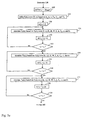
- the controller 104 of FIGS. 1 and 2 controls the precooking process generally according to the overall process flow of FIG. 3.
- the input parameters for the precooking process are defined and provided to the controller.
- the input parameters include a predefined time period ⁇ t for each real time step (or increment) [t r - ⁇ t, t r ] from the previous real time epoch t r - ⁇ t r to the current real time epoch t r during the process.
- This time period may range from 0.1 to 1 seconds.
- the input parameters also include the initial temperature T i and size, namely the, height H, width W, and length L, of the tuna fish being processed. These input parameters are manually measured by the operator before the tuna fish is placed in the precooker 102 of FIG. 1.
- the target backbone loin temperature T targ , the thermal conductivity k, the specific heat capacity C p , the density ⁇ , and the surface convective heat transfer coefficient h for the tuna fish type (or species) of the tuna fish 101 of FIG. 1 are also included as input parameters. These input parameters are predetermined using well known techniques.
- the precooking process has a heating phase and a cooling phase.
- the heating phase includes a come-up subphase and a processing subphase and is performed in the precooker 102 of FIG. 1.
- the input parameters therefore also include a scheduled initial precooking temperature T 0 and scheduled processing temperatures T 1 to T 3 .
- the come-up phase is used to bring the scheduled initial precooking temperature T 0 in the precooker 102 of FIG. 1 up to the scheduled maximum processing temperature T 1 .
- the processing subphase is used to precook the tuna fish 101 of FIG. 1 at the scheduled processing temperatures T 1 to T 3 for extraction and cleaning of the loins of the tuna fish.
- the cooling phase is used to cool the tuna fish after the heating phase so that the extraction and cleaning of the loins can take place.
- the cooling phase is not performed in the precooker 102 of the tuna fish precooking system 100 of FIG. 1. This is often the case in many tuna fish processing plants for capacity reasons.
- the precooker may also be used to partially or completely perform the cooling phase, as will be discussed in more detail in section 3.a.
- the input parameters also include scheduled begin times t 1 and t 2 .
- the scheduled begin time t 1 is for the processing subphase when the scheduled maximum processing temperature T 1 is reached.
- the scheduled begin time t 2 is for a time-temperature step during the heating phase in which the precooking process is stabilized at the scheduled maximum processing temperature T 1 .
- Also included in the input parameters is an estimated end time t end for the heating phase. All of these input parameters are dependent on several factors, such as the precooker type, the tuna fish type (or species), size, and source, and the tuna fish processing plant capacity. Moreover, they may be determined experimentally. For example, the scheduled begin time t 1 may be determined by using heat distribution tests for the precooker 102 of FIG. 1. Similarly, the estimated end time t end may be determined from the collected results of previous precooking processes performed in the precooker.
- step 126 of FIG. 3 the operator issues commands with the user interface 114 and/or the host computer 105 to invoke the control program 109. Then, the operator enters the input parameters ⁇ t, T i , H, W, L, T targ , T end , k, C p , ⁇ , h, T 0 to T 3 , t 1 , and t end with the user interface and/or the host computer.
- the control program loads the entered input parameters into the primary memory 113 for use by the programs 109 to 111. The execution of these programs is controlled and coordinated by the control program in the manner discussed next.
- the control program 109 of FIG. 2 first invokes the scheduling program 110 of FIG. 2.
- the process scheduling program defines a scheduled heating time-temperature profile T s (t) over a scheduled heating time interval [0, t 4 ] for the heating phase of the precooking process, where 0 is the scheduled begin time for the heating phase.
- an open bracket "["or "]” indicates that the corresponding time is included in the time interval while a closed bracket “("or")” indicates that the corresponding time is not included in the time interval.
- the profile is defined based on the input parameters ⁇ t, T i , H, W, L, T targ , k, C p , ⁇ , h, T 0 to T 3 , t 1 , and t end .
- the precise manner in which step 127 is performed will be discussed in detail in section 2.b.
- the scheduled heating time-temperature profile T s (t) covers the come-up and processing subphases of the heating phase.
- the profile has a come-up portion over a scheduled come-up time interval [0, t 1 ) for the come-up subphase, where 0 and t 1 are respectively the scheduled begin times for the come-up and processing subphases. Over this time interval, the come-up portion ramps up in temperature between the scheduled initial temperature T 0 and the scheduled maximum precooking temperature T 1 .
- the scheduled heating time-temperature profile T s (t) also has a processing portion over a scheduled processing time interval [t 1 , t 4 ] for the processing subphase, where t 4 is the scheduled end time for the processing subphase.
- the processing portion includes three decreasing time-temperature steps (or segments) to ramp the precooking process down from the scheduled processing temperature T 1 to the scheduled processing temperature T 3 .
- the time-temperature steps occur over respective scheduled time intervals [t 1 , t 2 ), [t 2 , t 3 ), and [t 3 , t 4 ] and at the respective scheduled constant processing temperatures T 1 , T 2 , and T 3 .
- t 1 , t 2 , and t 3 are respectively the scheduled begin times for the first, second, and third steps and t 4 is the scheduled end time for the third step.
- the control program 109 of FIG. 2 then causes the come-up subphase in step 128 to be administered by the control circuitry 117 of FIG. 2 at each real time epoch t r of the come-up subphase.
- the control circuitry does so in accordance with the come-up portion of the scheduled heating time-temperature profile T s (t) by appropriately controlling the precooker 102 of FIG. 1. This means that an actual time-temperature profile T a (t) for the precooking process is attempted to be brought up along the come-up portion over the scheduled come-up time interval [0, t 1 ).
- control circuitry controls the precooker and monitors the sensed actual temperature T a (t r ) at each real time epoch t r of the come-up subphase to make sure that this temperature stays at least equal to the corresponding scheduled come-up temperature T s (t r ) for that time epoch,
- the temperature T s (t r ) is obtained from the profile T s (t).
- step 130 the control program records the actual temperature T a (t r ) sensed at this epoch in the precooker of FIG. 1. By doing this at each real time epoch t r of the come-up subphase, the control program compiles a come-up portion of the actual time-temperature profile T a (t) over the come-up time interval [0, t 1 ).
- step 131 the simulation program simulates at each real time epoch t r of the come-up subphase a backbone loin temperature T b (t r ) at that epoch for the widest portion of the tuna fish 101 of FIG. 1. This is done based on the actual temperature T a (t r ) sensed at this epoch and recorded in step 131 since the actual temperature T a (t r ) may be different from the scheduled temperature T s (t r ). Furthermore, this also done based on the input parameters T i , W, H, L, k, C p , ⁇ , and h. The precise manner in which step 131 is performed is discussed in greater detail in section 2.c.
- step 132 the control program 109 of FIG. 2 determines whether the come-up subphase of the heating phase has been completed and the processing subphase is to begin. This is done by determining if the current real time epoch t r is the scheduled end time t 1 for the come-up subphase and if the actual temperature T a (t r ) has reached the scheduled processing temperature T 1 . If both of these conditions are not satisfied, then the control program returns to step 128 and steps 128 to 132 are repeated until this is determined in step 132. If both of these conditions are finally satisfied, the control program proceeds to step 133.
- the control program 109 of FIG. 2 causes the processing subphase to be administered in step 133 by the control circuitry 117 of FIG. 2 at each real time epoch t r of the processing subphase. Similar to in the come-up phase, the control circuitry does so in accordance with the processing portion of the scheduled heating time-temperature profile T s (t) by appropriately controlling the precooker 102 of FIG. 1. In this case, the actual time-temperature profile T a (t) for the precooking process is attempted to be maintained along the time-temperature steps of the processing portion over the scheduled processing time interval [t 1 , t 4 ].
- the temperature T s (t r ) is obtained from the profile T s (t).
- Steps 134 and 135 are similar to steps 129 and 130.
- the control program records the actual temperature T a (t r ) at this epoch sensed in the precooker of FIG. 1. Since this is done at each real time epoch t r of the processing subphase, the control program compiles a processing portion of the actual time-temperature profile T a (t) over the processing time interval (t 1 , t 4 ].
- Step 136 is similar to step 131.
- the simulation program simulates at each real time epoch t r of the processing subphase the backbone loin temperature T b (t r ) at that epoch. This is done in the same manner as step 131, except that the actual temperature T a (t r ) sensed at this epoch and recorded in step 135 is used.
- the precise manner in which step 136 is performed is discussed in greater detail in section 2.c.
- step 137 the control program 109 of FIG. 2 determines whether the processing subphase of the heating phase has been completed. This is done by determining whether the simulated backbone loin temperature T b (t r ) at the current real time epoch t r has reached the target backbone loin temperature T targ . If it has not, then the control program returns to step 133 and steps 133 to 137 are repeated until it is finally determined in step 137 that the processing subphase has been completed. The epoch at which this occurs is then the actual end time t 4 ' of the processing subphase. This is of course is also the actual end time of the heating phase. The processing subphase then stopped in step 138. This of course means that the heating phase is completed.
- the actual end time t 4 ' may occur before or after the scheduled end time t 4 . This is due to the fact that the simulation performed in steps 131 and 136 takes full thermal credit for the actual time-temperature profile T a (t). Thus, if the profile t 4 is lower than the scheduled time-temperature profile T s (t) for a significant time interval, as shown in the example of FIG. 4, then the actual time t 4 ' will occur after the scheduled time t 4 . For this kind of temperature deviation, the control program 109 of FIG. 2 will cause the control circuitry 117 of FIG.
- step 2 to continue to administer the processing subphase in step 133 at each real time epoch t r after the scheduled end time t 4 until the actual end time t 4 ' is reached.
- This is done by extending the scheduled time-temperature step at the scheduled temperature T 3 over an extended time interval [t 3 , t 4 '].
- the profile t 4 is higher than the scheduled time-temperature profile T s (t) for a significant time interval, then the actual end time t 4 ' will occur before the scheduled end time t 4 .
- the scheduled time-temperature step will be shortened over a shortened time interval [t 3 , t 4 '] for this kind of temperature deviation. In either case, an adjusted time-temperature step over an adjusted time interval results.
- the cooling phase is then performed after the heating phase. As mentioned earlier, the cooling phase is not performed in the precooker 102 of FIG. 1 in this embodiment of the tuna fish precooking system 100.
- tuna fish precooking process just described provides a significant increase in quality, yield, and energy savings compared to other types of tuna fish precooking processes. There are a number of reasons for this increase and they are described next.
- the use of the decreasing time-temperature steps in the scheduled time-temperature profile T s (t) also serve several important purposes.
- the heat transfer in the tuna fish 101 of FIG. 1 is slow and limited by the thermal conductivity of the loins.
- the decreasing time-temperature steps avoid overcooking of the loins in the thinner portions of the tuna fish.
- the last time-temperature step avoids overcooking of the loins in the thinner portions while allowing the loins in the thicker portions to still be cooked.
- the decreasing time-temperature steps also avoid breaking the skin of the tuna fish so that the loins will not be oxidized. This increases the quality and yield of the extracted loins.
- the ability to precisely predict when the target backbone loin temperature T targ has been reached is also very important. This prevents overcooking from occurring and increases the quality and yield of the extracted loins. Furthermore, energy is saved since the end of the heating phase is precisely determined.
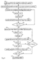
- FIG. 5 shows a detailed process flow for step 127 of FIG. 3. As indicated earlier in section 2.a., the scheduling program 110 of FIG. 2 uses this step to define the scheduled heating time-temperature profile T s (t).
- the scheduling program 110 of FIG. 2 defines the scheduled begin time t 3 of the time-temperature step at the scheduled processing temperature T 2 .
- this begin time is defined as one half of the estimated end time t end of the entire heating phase.
- the scheduling program 110 of FIG. 2 defines the scheduled heating time-temperature profile T s (t) over the time interval [0, t 3 ).
- the come-up portion of the profile over the time interval [0, t 1 ) is defined based on the scheduled begin time t 1 of the come-up subphase and the scheduled initial precooking and processing temperatures T 0 and T 1 .
- the first two time-temperature steps over the time intervals [t 1 , t 2 ) and [t 2 , t 3 ) in the processing portion of the profile are also defined.
- the first time-temperature step is defined based on the begin times t 1 and t 2 of the first two time-temperature steps and the scheduled processing temperature T 1 .
- the second time-temperature step is defined based on the begin times t 2 and t 3 of the last two time-temperature steps and the scheduled processing temperature T 2 .
- the scheduling program 110 of FIG. 2 then iteratively performs a simulation of the come-up subphase in sub-steps 150 to 153 of step 127.
- the current simulation time epoch t s is initially set to the begin time 0 of the come-up subphase.
- Steps 151 to 153 are then performed in each iteration of the come-up phase simulation.
- the scheduling program 110 of FIG. 2 invokes the simulation program 111 of FIG. 2 for step 151 of each iteration.
- step 151 of each iteration the backbone loin temperature T b (t s ) at the current simulation time epoch t s is simulated.
- This simulation is performed in the same manner as steps 131 and 136 of FIG. 3, except that the scheduled temperature T s (t s ) at this epoch is used.
- This scheduled temperature is obtained from the come-up portion of the scheduled heating time-temperature profile T s (t) over the time interval [0, t 1 ), which is defined in step 149.
- steps 131 and 136 the precise manner in which step 151 is performed is discussed in greater detail in section 2.c.
- step 152 of each iteration the previous simulation time epoch t s is incremented by the amount of the time period ⁇ t. This results in a new current simulation time epoch t s .
- step 153 of each iteration it is determined whether the come-up simulation has been completed. This is done by determining whether the current simulation time epoch t s is the scheduled begin time t 1 for the processing subphase. If it is not, then steps 151 to 153 are repeated until this is determined in step 153. When this finally occurs, the scheduling program 110 of FIG. 2 proceeds to step 154.
- the scheduling program 110 of FIG. 2 then iteratively performs a simulation of the scheduled first time-temperature step in the processing subphase. This is done with sub-steps 154 to 156 of step 127, which are performed in each iteration of this simulation. Steps 154 to 156 are the same as steps 151 to 153, except for some differences that will be described now.
- step 154 of each iteration the scheduled temperature T s (t s ) used to simulate the backbone loin temperature T b (t s ) is obtained from the scheduled first time-temperature step over the time interval [t 1 , t 2 ) in the scheduled heating time-temperature profile T s (t).
- the scheduled first time-temperature step is defined in step 149.
- step 156 of each iteration it is determined whether the current simulation time epoch t s is the scheduled end time t 2 for the scheduled first time-temperature step. In other words, it is determined whether the simulation of the scheduled first time-temperature step has been completed. If it is not, then steps 154 to 156 are repeated until this is determined in step 156. When this is finally occurs, the scheduling program 110 of FIG. 2 proceeds to step 157.
- the scheduling program 110 of FIG. 2 then iteratively performs a simulation of the scheduled second time-temperature step in the processing subphase. This is done with sub-steps 157 to 159 of step 127. These steps are performed in each iteration of this simulation. Steps 157 to 159 are the same as steps 154 to 156, except for the differences noted next.
- step 157 of each iteration the scheduled temperature T s (t s ) used to simulate the backbone loin temperature T b (t s ) is obtained from the scheduled second time-temperature step over the time interval [t 2 , t 3 ) in the scheduled heating time-temperature profile T s (t).
- the scheduled first time-temperature step is also defined in step 149.
- step 159 of each iteration it is determined whether the simulation of the scheduled second time-temperature step has been completed. This is done by determining if the current simulation time epoch t s is the scheduled end time t 3 for the scheduled second time-temperature step. If it is not, then steps 157 to 159 are repeated until this is determined in step 156. When this is finally occurs, the scheduling program 110 of FIG. 2 proceeds to step 160.
- the scheduling program 110 of FIG. 2 then iteratively performs a simulation of the third time-temperature step in the processing subphase. This is done with sub-steps 160 to 162 of step 127, which are performed in each iteration of this simulation. Steps 160 to 162 are also the same as steps 154 to 156, except for the differences mentioned next.
- step 161 of each iteration the backbone loin temperature T b (t s ) is simulated based on the scheduled processing temperature T 3 . Then, in step 162 of each iteration, it is determined whether the simulation of the third time-temperature step has been completed. This is done by determining whether the simulated backbone loin temperature T b (t s ) at the current simulation time epoch t s has reached the target backbone loin temperature T targ . If it has not, then steps 160 to 162 are repeated until it is finally determined in step 162 that the simulation of the third time-temperature step has been completed.
- step 163 of step 127 the current simulation time epoch t s at which this occurs is then defined by the simulation program of FIG. 2 as the scheduled end time t 4 of the third time-temperature step. This is also the scheduled end time of the processing subphase and the heating phase.
- the simulation program of FIG. 2 defines the scheduled third time-temperature step over the time interval [t 3 , t 4 ]. This is based on the end times t 3 and t 4 of the last two time-temperature steps and the scheduled processing temperature T 3 .
- control program 109 of FIG. 2 will then proceed to step 128 of FIG. 3 and begin administration of the come-up subphase. This is done in the manner discussed earlier in section 2.a.
- a backbone loin temperature T b (t s ) or T b (t r ) is simulated for the tuna fish 101 of FIG. 1 in steps 151, 154, 157 and 160 of FIG. 5, steps 131 and 136 of FIGS. 3 and 8, and step 172 of FIG. 8.
- the backbone loin temperature T b (t r ) is also simulated in step 142 of FIG. 9 (section 3.b. below). This temperature is simulated for the widest portion of the tuna fish, as mentioned in section 2.a. The same detailed simulation flow diagram is used for all of these steps and is shown in FIG. 6.
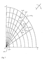
- the simulation program 111 of FIG. 2 includes a finite difference model utilizing volume elements ⁇ V 1,1 to ⁇ V 8,9 and ⁇ V b , as shown in FIG. 7. These volume elements are used to model the heat transfer at the widest portion of the tuna fish at a particular time epoch t e , where the time epoch t e is a simulation time epoch t s for steps 151, 154, 157, and 172 and is a real time epoch t r for steps 131, 136, and 142.
- Step 151 of FIG. 5 is the first time that a simulation will be done in the precooking process.
- step 151 has the sub-step 180 of FIG. 6 in which the volume elements are defined by the simulation program 111 of FIG. 2 for the entire precooking process. This is done based on the height H and width W of the tuna fish in the manner discussed next.
- the volume elements ⁇ V 1,1 to ⁇ V 8,9 and ⁇ V b lie in a quarter of the elliptical cross section of the tuna fish 101 of FIG. 1 at the widest portion and are constructed in a nodal system, with indexes i and j, in the manner shown in FIG. 7.
- Each node i,j is used to identify a corresponding volume element ⁇ V i,j and temperature T i,j (t e ) in the volume element at the node.
- the node b is used to identify the volume element ⁇ V b near the backbone of the tuna fish and the temperature T b (t e ) in the volume element at that node.
- the number (I)(J)+1 of volume elements (i.e., nodes) used is based on the height H and width W of the tuna fish 101 of FIG. 1.
- Each volume element ⁇ V i,j is defined to have two surface areas A i,j N and A i,j S along the j index, where N and S refer to North and South respectively, and two surface areas A i,j W and A i,j E along the i index, where W and E refer to West and East respectively.
- Each volume element is also defined to have a thickness of unity in the direction perpendicular to the i,j plane.
- each volume element and its corresponding surface areas are determined based on the height H and width W of the tuna fish 101 of FIG. 1 and the nodal system constructed in FIG. 7.
- the volume element ⁇ V b is somewhat different than the other volume elements ⁇ V 1,1 to ⁇ V 8,9 . It also has a thickness of unity in the direction perpendicular to the i,j plane. But, it includes 9 North surface areas A b N1 to A b N9 that are respectively adjacent (and equal) to the South surface areas A 8,1 S to A 8,9 S of the volume elements ⁇ V 8,1 to ⁇ V 8,9 .
- steps 151, 154, and 157 of FIG. 5, steps 131, 136, and 142 of FIGS. 3 and 8, and step 172 of FIG. 8 have steps 181 to 187 of FIG. 6 as sub-steps.
- the indexes i and j are set to 0.
- Steps 182 to 186 are then used by the simulation program 111 of FIG. 2 to simulate the temperatures T 1,1 (t e ) to T 8,9 (t e ) in the volume elements ⁇ V 1,1 to ⁇ V 8,9 in nested loop fashion.
- step 182 of each loop for the index i the simulation program 111 of FIG. 2 increments the previous index i by one to compute the current index i. Then, in step 183 of each loop for the index j, the simulation program increments the previous index j by one to compute the current index j.
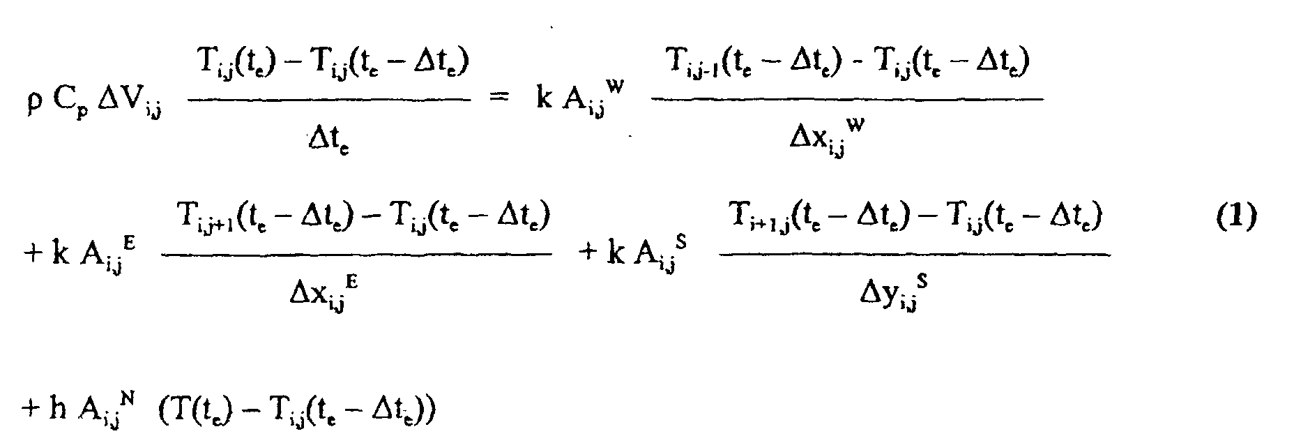
- step 184 of each loop for the index j the temperature T i,j (t e ) in the corresponding volume element ⁇ V i,j at the current time epoch t e is simulated.
- ⁇ x ij W , ⁇ x i,j E , and ⁇ y i,j S are respectively the distances between the node i,j and the adjacent nodes i,j-1, i,j+1, and i+1,j at the West, East, and South surface areas. These distances are also defined with the corresponding volume element.
- FIG. 7 shows the surface volume element ⁇ V 1,6 .
- this volume element and the other surface volume elements ⁇ V 1,2 to ⁇ V 1,5 and ⁇ V 1,7 to ⁇ V 1,8 all of the terms in Eq. 1 are used.
- the term with the temperature T i,j-1 (t e ) drops out because there is no adjacent volume element ⁇ V i,j-1 .
- the term with the temperature T i,j+1 (t e ) drops out for the surface volume element ⁇ V 1,9 .
- step 184 is performed in a similar manner to that just described for the surface volume elements ⁇ V 1,1 to ⁇ V 1,9 .
- the input parameter h is not used but the temperature T i-1,j (t e - ⁇ t) in the adjacent volume element ⁇ V i-1,j at the previous time epoch t e - ⁇ t and the corresponding North surface area A i,j N are used. This is due the fact that this volume element is in the interior of the tuna fish and will have a volume element ⁇ i-1,j below it.
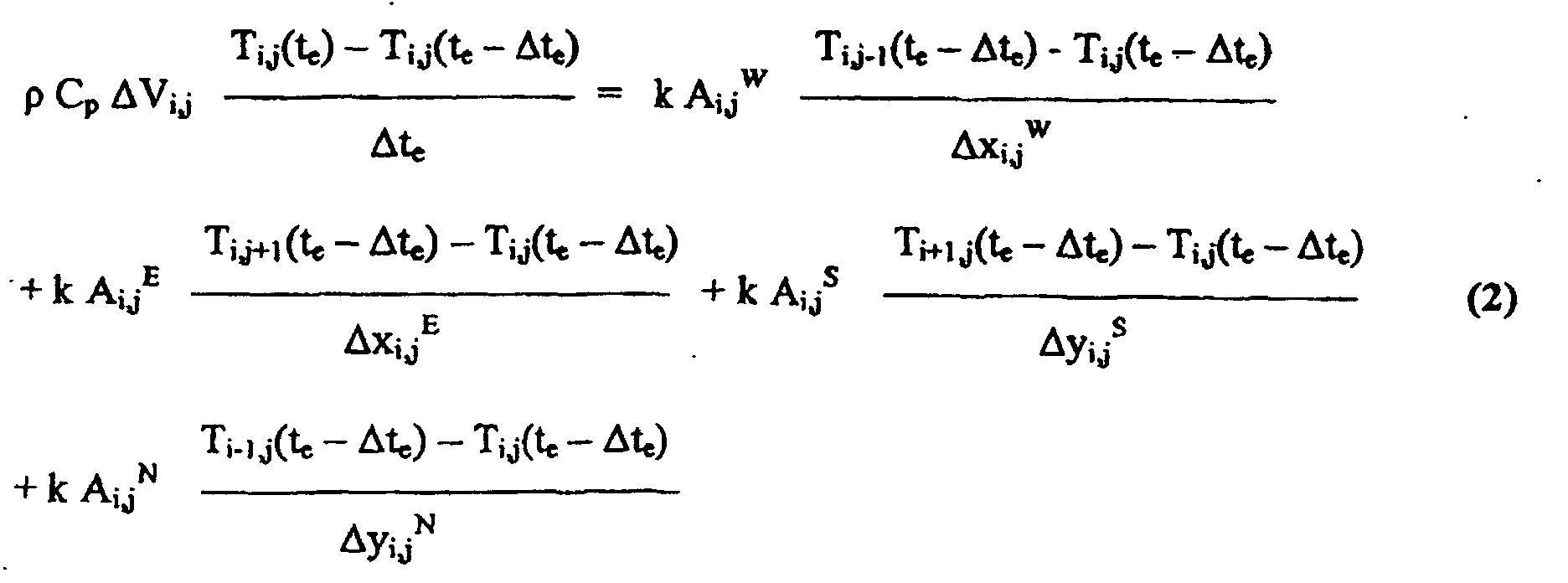
- the simulation is done according to: where ⁇ y i,j N is the distance between the node i,j and the adjacent node i-1,j at the North surface area.
- FIG. 7 also shows the interior volume element ⁇ V 3,7 .
- this volume element and the other interior volume elements ⁇ V 2,2 to ⁇ V 2,8 , ⁇ V 3,2 to ⁇ V 3,6 , ⁇ V 3,8 , ⁇ V 4,2 to ⁇ V 4,8 ,..., and ⁇ V 8,2 to ⁇ V 8,8 all of the terms in Eq. 1 are used.
- the interior volume elements ⁇ V 2,1 , ⁇ V 3,1 ,..., and ⁇ V 8,1 the term with the temperature T i,j-1 (t e ) drops out because there is no adjacent volume element ⁇ V i,j-1 .
- the term with the temperature T i,j+1 (t e ) drops out for the interior volume elements ⁇ V 2,9 , ⁇ V 3.9 ,..., and ⁇ V 8,9 .
- step 184 the time epoch t e is the current simulation time epoch t e and the temperature T(t e ) is the scheduled come-up or processing temperature T s (t s ) at this epoch in the case where step 184 is a sub-step of step 154, 157, or 160.
- step 184 is a sub-step of step 172
- the time epoch t e is the current simulation time epoch t s and the temperature T(t e ) is the scheduled cooling temperature T 4 .
- the time epoch t e is the current real time epoch t r and the temperature T(t e ) is the actual temperature T a (t r ) at this epoch in the case where step 184 is a sub-step of step 131, 136, or 142.
- step 185 of each loop for the index j the simulation program 111 of FIG. 2 determines if the index has reached 9. If it has not, then steps 183 to 185 are repeated until this is finally determined. In this way, all of the temperatures T i,1 (t e ) to T i,9 (t e ) in the corresponding volume elements ⁇ V i,j to ⁇ V i,9 with same index i are simulated in the same loop with the current index i.
- step 186 of each loop for the index i the simulation program 111 of FIG. 2 determines if this index has reached 8. If it has not, then steps 182 to 186 are repeated until this is finally determined. This results in all of the temperatures T 1,1 (t e ) to T 8,9 (t e ) in all of the volume elements ⁇ V 1,1 to ⁇ V 8,9 being simulated.
- step 187 the temperature T b (t e ) in the final volume element ⁇ V b is simulated by the simulation program 111 of FIG. 2. This is done based on the input parameters k, C p , and ⁇ , the temperatures T b (t e - ⁇ t) and T 8,1 (t e - ⁇ t) to T 8,9 (t e - ⁇ t) in that volume element ⁇ V b and the adjacent volume elements ⁇ V 8,1 to ⁇ V 8,9 at the previous time epoch t e - ⁇ t, and the corresponding North surface areas A b N1 to A b N9 .
- the simulation is done according to; where ⁇ y b NI to ⁇ y b NJ are respectively the distances between the node b and the adjacent nodes I,1 to I,J at the North surface area.
- the time epoch t e is the current simulation time epoch t s in the case where step 184 is a sub-step of step 154, 157, 160 or 172 and is the current real time epoch t r in the case where step 184 is a sub-step of step 131, 136, or 142.
- control program 109 of FIG. 2 will then proceed to step 152, 155, 158, or 161 of FIG. 5, step 132 or 137 of FIG. 3, step 132 or 170 of FIG. 8 or step 143 of FIG. 9. This is done in the manner discussed in sections 2.a., 2.b., or 3.a.
- FIGS. 1 to 6 and sections 1. and 2. disclose an exemplary embodiment of the invention. However, alternative embodiments that utilize the principles and concepts developed for that exemplary embodiment do exist.
- the foregoing exemplary embodiment of the invention is conservative. This is due to the fact that the overall process flow diagram of FIG. 3 provides a conservative approach for determining when the target backbone loin temperature T targ has been reached. Specifically, the backbone loin temperature T b (t r ) at each real time epoch t r is simulated in steps 131 and 136 and compared against the target backbone loin temperature in step 137. However, as mentioned earlier, the heat transfer in the tuna fish 101 of FIG. I is slow. Therefore, the backbone loin temperature will continue to increase over a portion of the cooling phase and the maximum backbone loin temperature reached during the precooking process will exceed the target backbone loin temperature. This may result in the tuna fish being overcooked.
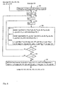
- FIG. 8 shows another overall process flow diagram for a more aggressive embodiment of the invention.
- steps 126 to 136 and 138 are the same as those in the overall process flow diagram of FIG. 3, except that a scheduled cooling temperature T 4 is defined in step 126 as one of the input parameters.
- step 170 the control program 109 of FIG. 2 sets a current simulation time epoch t s to the current real time epoch t r . This is done so that steps 171 to 174 can be used to iteratively simulate the cooling phase with the assumption that the processing subphase has ended at the current real time epoch.
- step 171 of each iteration the control program 109 of FIG. 2 increments the previous simulation time epoch t s by the amount of the time period ⁇ t. This results in a new current simulation time epoch t s .
- the control program 109 of FIG. 2 invokes the simulation program 111 of FIG. 2 for step 172 of each iteration.
- the simulation program simulates at the current simulation time epoch t s of the cooling phase the backbone loin temperature T b (t s ) at that epoch. This is done in the same manner as in steps 131 and 136 of FIG. 3, except that it is based on the scheduled cooling temperature T 4 .
- steps 131 and 136 the precise manner in which step 172 is performed is discussed in greater detail in section 2.c.
- step 173 of each iteration the process control program 109 of FIG. 2 determines whether the simulated backbone loin temperature T b (t s ) at the current simulation time epoch t s has reached the target backbone loin temperature T targ . If this condition is satisfied, then this means that the processing subphase can end at the current real time epoch t r since the target backbone loin temperature T targ . will be reached during the cooling phase. In this case, the control program ends the processing subphase in step 138. However, if the condition is not satisfied, then the process control program proceeds to step 174.
- step 174 of each iteration the process control program 109 of FIG. 2 determines if the simulated backbone loin temperature T b (t s ) at the current simulation time epoch t s is lower than the simulated backbone loin temperature T b (t s - ⁇ t) at the previous simulation time epoch t s - ⁇ t. If the condition of step 174 is satisfied, then this means that the target backbone loin temperature T targ . will not be reached during the cooling phase if the processing subphase were to end at the current real time epoch t r . As a result, the control program 109 returns to step 133.
- Steps 133 to 136 and 170 to 174 are then repeated until it is finally determined in step 173 that the target backbone loin temperature T targ will be reached during the cooling phase if the processing subphase is ended at the current real time epoch. If the condition of step 174 is not satisfied, then it is possible that the target backbone loin temperature T targ will be reached during the cooling phase. In this case, steps 171 to 174 are repeated until one of the conditions of steps 173 and 174 are satisfied.
- the scheduled heating time-temperature profile T s (t) over the scheduling time interval [0, t 4 ] could be more aggressively defined in step 127 using the concepts just described. This would involve adjusting the scheduling flow diagram of FIG. 5 in a similar manner to the way in which the overall process flow diagram of FIG. 3 was adjusted to produce the more aggressive overall process flow diagram of FIG. 8. However, it may be more desirable to still use the scheduling flow diagram of FIG. 5 to obtain a conservative scheduled heating time-temperature profile so as to define the outer bounds of the heating phase.
- the cooling phase is performed external to the precooker of FIG. 1 in the first exemplary embodiment.
- the precooker in fact may perform the cooling phase.
- FIG. 9 shows an overall process flow diagram for controlling the cooling phase in this case and could be used with the overall process flow diagram of FIG. 3 or 8. But, step 126 would include defining a scheduled cooling temperature T 4 for the cooling phase and an end backbone loin temperature T end as input parameters.
- step 139 the control program causes the cooling phase to be administered by the control circuitry 117 of FIG. 2 at each real time epoch t r of the cooling phase.
- the control circuitry does so in accordance with the scheduled cooling temperature T 4 by appropriately controlling the precooker 102 of FIG. 1.
- the actual time-temperature profile t 4 for the precooking process is attempted to be maintained constant at the scheduled cooling temperature.
- control circuitry controls the precooker and monitors the sensed actual temperature T a (t r ) at each real time epoch t r of the cooling phase to make sure that this temperature stays at least equal to the scheduled cooling temperature T 4 .
- step 141 which is similar to steps 130 and 135 of FIGS. 3 and 8, the control program records the actual temperature T a (t r ) at this epoch sensed in the precooker 102 of FIG. 1.
- the control program also compiles a cooling portion of the actual time-temperature profile t 4 over a cooling time interval (t 4 , t 5 ] by doing this at each real time epoch t r of the cooling phase.
- the control program 109 of FIG. 2 once again invokes the simulation program 111 of FIG. 2 for step 142. Similar to steps 131 and 136 of FIGS. 3 and 8, the simulation program simulates at each real time epoch t r of the processing subphase the backbone loin temperature T b (t r ) at that epoch in step 142. In this case, however, the actual temperature T a (t r ) sensed at this epoch and recorded in step 141 is used. As with steps 131 and 136, the precise manner in which step 142 is performed is discussed in greater detail in section 2.c.
- step 143 the control program 109 of FIG. 2 determines in step 143 whether the cooling phase has been completed. This is done by determining whether the simulated backbone loin temperature T b (t r ) at the current real time epoch t r has reached the end backbone loin temperature T end . If it has not, then the control program returns to step 139 and steps 139 to 143 are repeated until it is finally determined in step 143 that the cooling phase has been completed. The precooking process is then stopped in step 144. The epoch at which this occurs is then the actual end time t 5 of the cooling phase and, of course, is also the actual end time of the entire precooking process.
- the precooking system 100 may perform a precooking process according to these decreasing time-temperature steps without on-line control of heat transfer in the manner discussed in section 2.a. and shown in FIG. 3.
- these decreasing time-temperature steps can be used without simulating the backbone loin temperature T b (t r ) or T b (t s ) to determine if a target backbone loin temperature has been reached.
- time-temperature steps may be used in the scheduled heating time-temperature profile T s (t).
- the number of decreasing time-temperature steps may depend on the type, size, and source of the tuna fish. It also may depend on the type of precooker that precooker 102 of FIG. 2 is.
- the profile may have ramping up and/or down linear, exponential, square wave, and/or curvilinear portions. This is particularly true where, as discussed next in section 3.e., the invention is used for any food preparation process where heat transfer is involved.
- a tuna fish precooking process was used to describe the invention in detail.
- the invention can be used in any food preparation process in which heat transfer is used to prepare a food item for further processing or consumption.
- a food item may be a meat item, such as poultry, beef, pork, fish, shellfish, etc.
- it could be a vegetable or fruit item.
- the tuna fish precooking system 100 is a food preparation system
- the precooker 102 is a heating and/or cooling chamber
- the tuna fish 101 is the food item
- the simulated backbone loin temperature T b (t r ) or T b (t s ) is a simulated internal temperature in the food item
- the target and end backbone loin temperatures T targ and T end are respectively target and end internal temperatures for the food item.
Landscapes
- Engineering & Computer Science (AREA)
- Food Science & Technology (AREA)
- Physics & Mathematics (AREA)
- General Physics & Mathematics (AREA)
- Automation & Control Theory (AREA)
- Feedback Control In General (AREA)
- Control Of Temperature (AREA)
- General Preparation And Processing Of Foods (AREA)
- Control Of Heat Treatment Processes (AREA)
- Exposure Of Semiconductors, Excluding Electron Or Ion Beam Exposure (AREA)
- Meat, Egg Or Seafood Products (AREA)
Abstract
Description


Claims (20)
- A method of modelling heat transfer in a food item (101), the method comprising the steps ofcharacterised by the step of:transferring heat to or from the food item (101) during a phase of the heat transfer process;sensing actual temperature in the heat transfer process externally of the food item during the phase;at each one of multiple real time epochs of the phase, by means of a finite element model of the food item, simulating an internal temperature in the food item based on the sensed actual external temperature at that real time epoch.
- The method of claim 1 further characterised in that the simulated internal temperature at each one of the real time epochs comprises a current internal temperature of the food item (101) predicted at that real time epoch.
- A method for precisely performing a heat transfer process on a food item (101), characterised in that the method of modelling heat transfer as defined in claim 1 or 2 is used to simulate the internal temperatures in the food item at the multiple real time epochs, the phase of the heat transfer process being terminated when the simulated internal temperature at a particular one of the real time epochs reaches a target internal temperature.
- The method of claim 3 further characterised by the step of:wherein the simulating step comprises the steps of:controlling the heat transfer process according to a scheduled time-temperature profile;wherein the simulated internal temperature at each one of the real time epochs comprises the maximum internal temperature simulated at that real time epoch.at each one of the real time epochs, simulating a current internal temperature predicted in the food item (101) for that real time epoch based on the sensed actual external temperature at that real time epoch; andat each one of the real time epochs, simulating a maximum internal temperature predicted in the food item for a later epoch after that real time epoch based on the simulated current internal temperature at that real time epoch and the scheduled time-temperature profile after that real time epoch; and
- The method of claim 3 or 4 further characterised in that the food item (101) comprises a tuna fish, the heat transfer process comprises a tuna fish pre-cooking process, and the simulated internal temperature at each one of the real time epochs is for the backbone of the tuna fish.
- The method of any of claims 3 to 5 further characterised by the step of:providing input parameters comprising the size, thermal conductivity, specific heat capacity, density, and surface convective heat transfer coefficient for the food item (101).
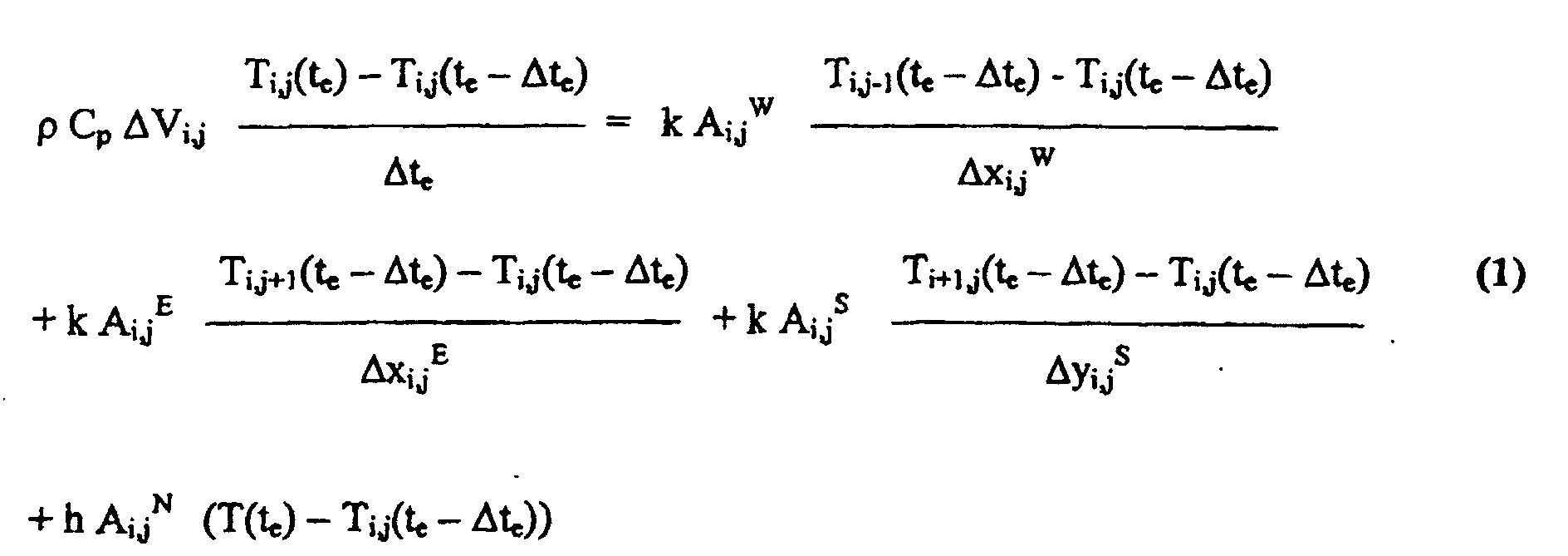
- The method of claim 6 wherein the simulating step is performed according to a finite difference model and comprises the steps of:dividing the food item into volume elements ΔV1,1 to ΔVI,J and a center volume element ΔVb along a cross section of the food item using a nodal system with nodes 1,1 to I,J and a center node b, each node i,j identifying the corresponding volume element ΔVi,j, where i = 1 to I and j = 1 to J, the center node b identifying the center volume element ΔVb ;at each one te of the real time epochs, simulating the temperature Ti,j(te) for each volume element ΔVi,j along the surface of the food item, where i = 1 and j = 1 to J, according to:at each one te of the real time epochs, simulating the temperature TI,j(te) for each volume element ΔVi,j in the interior of the food item, where i = 2 to I and j = 1 to J, according to:
 at each one te of the real time epochs, simulating the temperature Tb(te) for the center volume element ΔVb according to:
 where: k, Cp, ρ, and h respectively represent the thermal conductivity, the specific heat capacity, the density, and the surface convective heat transfer coefficient of the food item; Ai,j W, Ai,j E, Ai,j N, and Ai,j S respectively represent west, east, north, and south surface areas of the volume element ΔVi,j ;
Δxi,j W, Δxi,j E, Δyi,j N, and Δyi,j S respectively represent the distances between the node i,j and the nodes i,j-1, i,j+1, i-1,j, and i+1,j at the west, east, north, and south surface areas Ai,j W, Ai,j E, Ai,j N, and Ai,j S ;
Δte represents the time between the real time epoch te and the previous real time epoch te - Δte;
T(te) represents the temperature in the chamber at the real time epoch te ;
Ti,j-1(te -Δte), Ti,j+1(te -Δte), Ti-1,j(te -Δte), and Ti+1,j(te -Δte) respectively represent the temperatures in the volume elements ΔVi,j-1, ΔVi,j+1, ΔVi-1,j, and ΔVi+1,j ;
Ab Nj represents a north surface area of the center volume element ΔVb adjacent to the south surface area AI,j S of the volume element ΔVi,j ; and
Δyb Nj represents the distance between the center node b and the node I,j. - The method of claim 7 further characterised in that the food item (101) comprises a tuna fish and the center volume element ΔVb is at the backbone of the tuna fish.
- The method of claim 7 or 8 further characterised in that the cross section comprises an elliptical cross section and the volume elements lie in a quarter of the elliptical cross section.
- The method of claim 7 farther characterised in that:the term in Eq. 2 with the temperature Ti,j-1(te -Δte) drops out for the volume elements ΔV2,I to ΔVI,1 ; andthe term in Eq. 2 with the temperature Ti,j+1(te -Δte) drops out for the volume elements ΔV2,J to ΔVI,J.
- The method of any of claims 3-10 further characterised in that the heat transferring step is controlled based on the sensed actual temperatures and according to a scheduled time-temperature profile, the scheduled time-temperature profile comprising decreasing time-temperature steps, the decreasing time-temperature steps being of such magnitude and duration that, in combination with the thermal properties of the food item (101), an internal temperature within the food item continues to increase throughout said decreasing time-temperature steps so as to attain said target value of said internal temperature.
- The method of claim 11 further characterised in that the time-temperature steps comprise only three decreasing time-temperature steps over a phase of the heat transfer process.
- The method of claim 11 or 12 further characterised in that the food item (101) comprises a tuna fish, the heat transfer process comprises a tuna fish pre-cooking process, the phase comprises a heating phase, and the target temperature is for the backbone of the tuna fish.
- A controller (104) for use in a food preparation system (100) to control a heat transfer process performed by the food preparation system on a food item (101), the controller comprising:characterised in that the controller simulates an internal temperature in the food item (101) at each one of multiple real time epochs of the phase, by means of a finite element model, based on the sensed external temperature at that real time epoch; andcontrol circuitry (117) to control a phase of the heat transfer process and receive sensed actual temperatures external to the food item (101) during a phase of the heat transfer process;the control circuitry (117) being operative to control the heat transfer process based on the sensed actual external temperatures during the phase;
causes the control circuitry (117) to terminate the phase when the simulated internal temperature at a particular one of the real time epochs reaches a target internal temperature. - A controller as defined in claim 14, further characterised in that a control computer (106) is coupled to the control circuitry (117) for simulating the internal temperatures, causing the control circuitry (117) to control the heat transfer process based on the sensed actual external temperatures during the phase and causing the control circuitry (117) to terminate the phase when the simulated internal temperature at a particular one of the real time epochs reaches the target internal temperature.
- A food preparation system (100) for precisely performing a heat transfer process on a food item (101) in which heat is transferred to or from the food item, the food preparation system comprising a sensor (103) configured to sense said external temperature during said phase of the heat transfer process;
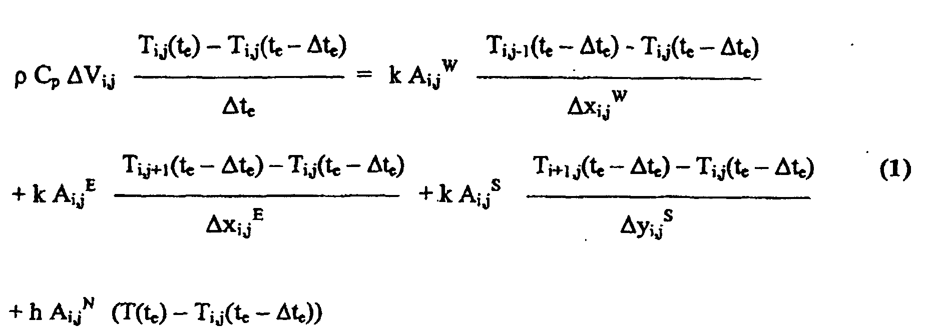
characterised in that a controller as defined in claim 14 or 15 is used to control the heat transfer process. - A food preparation system (100) as defined in claim 16, further characterised in that the internal temperature is simulated according to a finite difference simulation model by:dividing the food item into volume elements ΔV1,I to ΔVI,J and a center volume element ΔVb along a cross section of the food item using a nodal system with nodes 1,1 to I,J and a center node b, each node i,j identifying. the corresponding volume element ΔVi,j, where i = 1 to I and j = 1 to J, the center node b identifying the center volume element ΔVb ;at each one te of the real time epochs, simulating the temperature Ti,j(te) for each volume element ΔVi,j along the surface of the food item, where i = 1 and j = 1 to J, according to:at each one te of the real time epochs, simulating the temperature Ti,j(te) for each volume element ΔVi,j in the interior of the food item, where i = 2 to I and j = 1 to J, according to:
 at each one te of the real time epochs, simulating the temperature Tb(te) for the center volume element ΔVb according to:
 where: k, Cp, ρ, and h respectively represent the thermal conductivity, the specific heat capacity, the density, and the surface convective heat transfer coefficient of the food item; Ai,j W, Ai,j E, Ai,j N, and Ai,j S respectively represent west, east, north, and south surface areas of the volume element ΔVi,j ;
Δxi,j W, Δxi,j E, Δyi,j N, and Δyi,j S respectively represent the distances between the node i,j and the nodes i,j-1, i,j+1, i-1,j, and i+1,j at the west, east, north. and south surface areas Ai,j W, Ai,j E, Ai,j N, and Ai,j S ;
Δte represents the time between the real time epoch te and the previous real time epoch te - Δte;
T(te) represents said external temperature at the real time epoch te;
Ti,j-1(te -Δte), Ti,j+1(te -Δte), Ti-1,j(te -Δte), and Ti+1,j(te -Δte) respectively represent the temperatures in the volume elements ΔVi,j-1, ΔVi,j+1, ΔVi-1,j, and ΔVi+1,j ;
Ab Nj represents a north surface area of the center volume element ΔVb adjacent to the south surface area A1,j S of the volume element ΔVI,j ; and
Δyb Nj represents the distance between the center node b and the node I,j. - A computer readable memory (124) for directing a controller (104) with a computer (106) to control a heat transfer process performed on a food item (101), the computer readable memory (124) comprising:a control program (109) executable by the computer (106) and programmed to cause the controller (104) to control a phase of the heating transfer process based on sensed actual temperatures external to the food item (101) during the phase;a simulation program (111) executable by the computer (106), characterised in thatthe simulation program is programmed to, at each one of multiple real time epochs of the phase, by means of a finite element model of the food item simulate an internal temperature in the food item (101) based on the sensed actual external temperature at that real time epoch;the control program (109) being further programmed to cause the controller (104) to terminate the phase when the simulated internal temperature at a particular one of the real time epochs reaches a target internal temperature.
- A computer (106) configured to model heat transfer in a food item (101), the computer comprising:where: k, Cp, p, and h respectively represent the thermal conductivity, the specific heat capacity, the density, and the surface convective heat transfer coefficient of the food item;a memory (113) storing a simulation program (111), characterised in that the simulation program is programmed to:divide the food item into volume elements ΔV1,1 to ΔVI,J and a center volume element ΔVb along a cross section of the food item using a nodal system with nodes 1,1 to I,J and a center node b, each node i,j identifying the corresponding volume element ΔVi,j, where i = 1 to I and j = 1 to J, the center node b identifying the center volume element ΔVb;at a time epoch tc, simulate the temperature Ti,j(te) for each volume element ΔVi,j along the surface of the food item, where i = 1 and j = I to J, according to:at the time epoch te, simulate the temperature Ti,j(te) for each volume element ΔVi,j in the interior of the food item, where i = 2 to I and j = 1 to J, according to:
 at the time epoch te, simulating the temperature Tb(te) for the center volume element ΔVb according to:

Ai,j W, Ai,j E, Ai,j N, and Ai,j S respectively represent west, east, north, and south surface areas of the volume element ΔVi,j ;
Δxi,j W, Δxi,j E, Δyi,j N, and Δyi,j S respectively represent the distances between the node i,j and the nodes i,j-1, i,j+1, i-1,j, and i+1,j at the west, east, north and south surface areas Ai,j W, Ai,j E, Ai,j N, and Ai,j S ;
Δte represents the time between the time epoch te and the previous time epoch te -Δte ;
T(te) represents the temperature in the chamber at the time epoch te ;
Ti,j-1(te -Δte), Ti,j+1(te -Δte), Ti-1,j(te -Δte), and Ti+1,j(te -Δte) respectively represent the temperatures in the volume elements ΔVi,j-1, ΔVi,j+1, ΔVi-1,j, and ΔVi+1,j;
Ab Nj represents a north surface area of the center volume element ΔVb adjacent to the south surface area AI,j S of the volume element ΔVI,j ; and
Δyb Nj represents the distance between the center node b and the node I,j; and
a microprocessor (107) coupled to the memory (113) and configured to execute the simulation program. - A computer readable memory according to claim 18, characterised in that the computer readable memory comprises a simulation program (111) programmed to: divide the food item into volume elements ΔV1,1 to ΔVI,J and a center volume element ΔVb along a cross section of the food item using a nodal system with nodes 1,1 to I,J and a center node b, each node i,j identifying the corresponding volume element ΔVi,j, where i = 1 to I and j = 1 to J, the center node b identifying the center volume element ΔVb ;
at a time epoch te, simulate the temperature Ti,j(te) for each volume element ΔVi,j along the surface of the food item, where i = 1 and j = 1 to J, according to:at the time epoch te, simulate the temperature Ti,j(te) for each volume element ΔVi,j in the interior of the food item, where i = 2 to I and j = 1 to J, according to: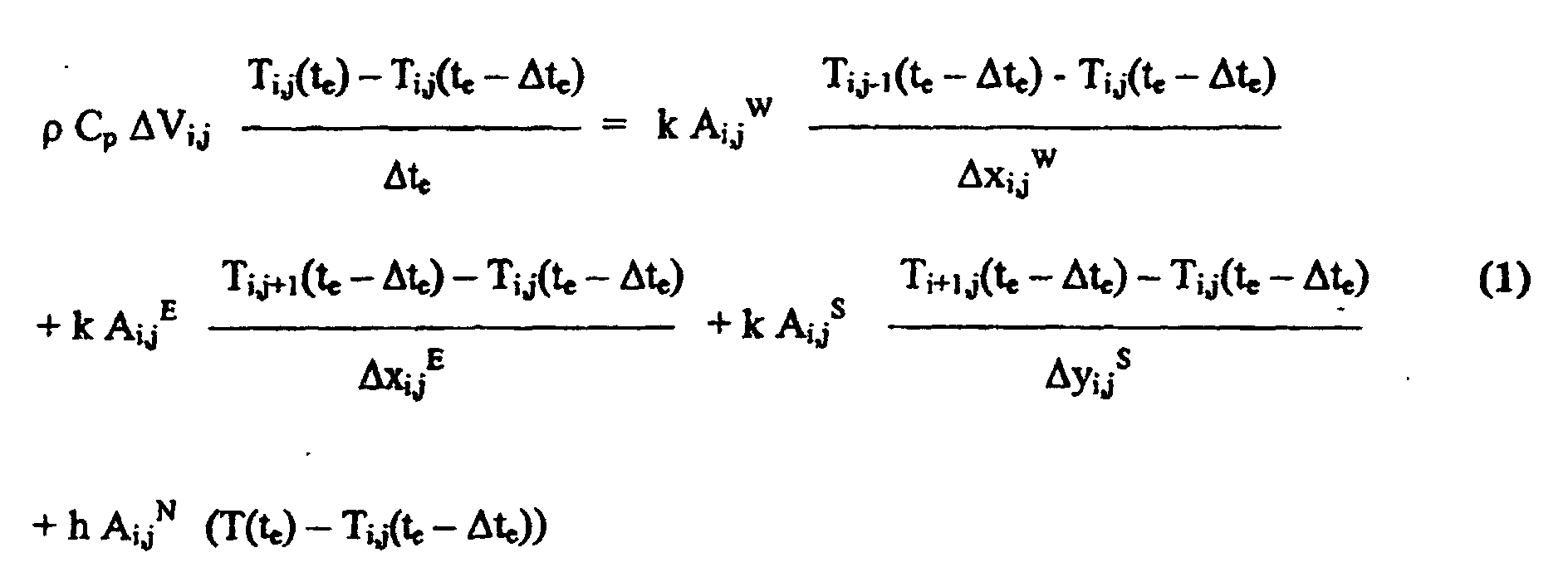 at the time epoch te, simulate the temperature Tb(te) for the center volume element ΔVb according to:
 where: k, Cp, ρ, and h respectively represent the thermal conductivity, the specific heat capacity, the density, and the surface convective heat transfer coefficient of the food item; Ai,j W, Ai,j E, Ai,j N, and Ai,j S respectively represent west, east, north, and south surface areas of the volume element ΔVi,j;
Δxi,j W, Δxi,j E, Δyi,j N, and Δyi,j S respectively represent the distances between the node i,j and the nodes i,j-1, i,j+1, i-1,j, and i+1,j at the west, east, north, and south surface areas Ai,j W,
Ai,j E, Ai,j N, and Ai,j S ;
Δte represents the time between the time epoch te and the previous time epoch te -Δte ;
T(te) represents the temperature external to the food item at the time epoch te ;
Ti,j-1(te -Δte), Ti,j+1(te -Δte), Ti-1,j(te -Δte), and Ti+1,j(te -Δte) respectively represent the temperatures in the volume elements ΔVi,j-1, ΔVi,j+1, ΔVi-1,j, and ΔVi+1,j ;
Ab Nj represents a north surface area of the center volume element ΔVb adjacent to the south surface area AI,j S of the volume element ΔVI,j ; and
Δyb Nj represents the distance between the center node b and the node I,j.
Applications Claiming Priority (3)
| Application Number | Priority Date | Filing Date | Title |
|---|---|---|---|
| US259919 | 1999-03-01 | ||
| US09/259,919 US6153860A (en) | 1999-03-01 | 1999-03-01 | System, controller, computer readable memory, and method for precise on-line control of heat transfer in a food preparation process |
| PCT/US2000/004029 WO2000052546A1 (en) | 1999-03-01 | 2000-02-17 | System, controller, computer readable memory, and method for precise on-line control of heat transfer in a food preparation process |
Publications (2)
| Publication Number | Publication Date |
|---|---|
| EP1157319A1 EP1157319A1 (en) | 2001-11-28 |
| EP1157319B1 true EP1157319B1 (en) | 2003-05-07 |
Family
ID=22986987
Family Applications (1)
| Application Number | Title | Priority Date | Filing Date |
|---|---|---|---|
| EP00907303A Expired - Lifetime EP1157319B1 (en) | 1999-03-01 | 2000-02-17 | System, controller, computer readable memory, and method for precise on-line control of heat transfer in a food preparation process |
Country Status (7)
| Country | Link |
|---|---|
| US (2) | US6153860A (en) |
| EP (1) | EP1157319B1 (en) |
| AT (1) | ATE239933T1 (en) |
| AU (1) | AU2882500A (en) |
| DE (1) | DE60002565D1 (en) |
| ES (1) | ES2199136T3 (en) |
| WO (1) | WO2000052546A1 (en) |
Cited By (2)
| Publication number | Priority date | Publication date | Assignee | Title |
|---|---|---|---|---|
| DE102015107228A1 (en) * | 2015-05-08 | 2016-11-10 | Lechmetall Gmbh | Method for controlling at least one sub-process of at least one cooking process and system for cooking food |
| US11162827B1 (en) | 2020-04-08 | 2021-11-02 | Balluff Gmbh | Method and system for determining at least one physical value |
Families Citing this family (25)
| Publication number | Priority date | Publication date | Assignee | Title |
|---|---|---|---|---|
| US6440361B2 (en) | 1998-11-06 | 2002-08-27 | Fmc Technologies, Inc. | Controller and method for administering and providing on-line handling of deviations in a hydrostatic sterilization process |
| US6472008B2 (en) | 1998-11-06 | 2002-10-29 | Fmc Technologies, Inc. | Method for administering and providing on-line correction of a batch sterilization process |
| US6410066B1 (en) | 1998-11-06 | 2002-06-25 | Fmc Technologies, Inc. | Controller and method for administering and providing on-line handling of deviations in a continuous oven cooking process |
| US6416711B2 (en) | 1998-11-06 | 2002-07-09 | Fmc Technologies, Inc. | Controller and method for administering and providing on-line handling of deviations in a rotary sterilization process |
| US6153860A (en) | 1999-03-01 | 2000-11-28 | Fmc Corporation | System, controller, computer readable memory, and method for precise on-line control of heat transfer in a food preparation process |
| US6820435B2 (en) | 2001-03-23 | 2004-11-23 | Electrolux Home Products, Inc. | Cooling enhancement device |
| US6967754B2 (en) * | 2001-12-14 | 2005-11-22 | Bratt Nicholas E | Hybrid optical transceivers for free space optical communication |
| DE10228139A1 (en) * | 2002-06-24 | 2004-01-22 | BSH Bosch und Siemens Hausgeräte GmbH | Household appliance, in particular hob with a storage unit |
| US7038172B1 (en) | 2003-05-16 | 2006-05-02 | Marshall Air Systems, Inc. | Conveyorized food broiling apparatus |
| WO2008075687A1 (en) | 2006-12-19 | 2008-06-26 | Daikin Industries, Ltd. | Control circuit for cooling apparatus, cooling system and method for controlling cooling apparatus |
| MX2010004307A (en) | 2007-12-19 | 2010-05-14 | Tipper Tie Inc | Rotating multi-clipper platform systems with cooperating adhesive seal modules, adhesive seal systems and associated devices and related methods. |
| US8337757B2 (en) * | 2008-02-07 | 2012-12-25 | Precision Combustion, Inc. | Reactor control method |
| US20100139497A1 (en) * | 2008-12-05 | 2010-06-10 | Prince Castle Inc. | Food heating device |
| US8789459B2 (en) * | 2008-12-05 | 2014-07-29 | Terry Tae-Il Chung | Food heating device |
| GB0912288D0 (en) * | 2009-07-15 | 2009-08-26 | Juggling Paradigms Sarl | Training device |
| WO2013036209A1 (en) * | 2011-09-09 | 2013-03-14 | Thailand Research Fund | System and method for cooking seafood products |
| US20130236614A1 (en) * | 2012-03-10 | 2013-09-12 | Hamilton Beach Brands, Inc. | Kitchen Appliance & Method of Using Same |
| US10344985B2 (en) * | 2013-03-16 | 2019-07-09 | Lawrence E Anderson | Oven time and temperature device and method of computing oven cookng time |
| US20190331342A1 (en) * | 2013-03-16 | 2019-10-31 | Lawrence Anderson | Method and Device for Cooking |
| GB2512128B (en) * | 2013-03-21 | 2016-03-02 | Enigin Plc | Force-cooled food refrigeration system |
| US10085584B2 (en) * | 2014-06-09 | 2018-10-02 | Whirlpool Corporation | Method of regulating temperature for sous vide cooking and apparatus therefor |
| US20180353004A1 (en) * | 2014-10-11 | 2018-12-13 | Yuanji Zhu | Systems and Methods for Automated Food Preparation |
| US10244766B2 (en) * | 2015-12-09 | 2019-04-02 | Brian E. Bartlett | System, device, and method for oven temperature control in tortilla and tortilla chip production |
| US12046306B2 (en) * | 2022-05-27 | 2024-07-23 | Sandisk Technologies Llc | Temperature dependent programming techniques in a memory device |
| CN115875731B (en) * | 2023-01-09 | 2025-08-01 | 黑龙江龙唐电力投资有限公司 | Intelligent control method for secondary network of heating system based on demand side regulation and control |
Family Cites Families (30)
| Publication number | Priority date | Publication date | Assignee | Title |
|---|---|---|---|---|
| US3326692A (en) | 1964-09-14 | 1967-06-20 | Mcdonald S Systems Inc | Method of and apparatus for cooking |
| US4345145A (en) | 1980-05-19 | 1982-08-17 | General Electric Company | User programmable control system for toaster oven appliance |
| US4437159A (en) * | 1981-05-15 | 1984-03-13 | The Frymaster Corporation | Cooking computer |
| DE3323399C2 (en) * | 1983-06-29 | 1985-04-25 | Kurt Wolf & Co Kg, 7547 Wildbad | Device for controlling the cooking or cooking process in a steam pressure cooker |
| ES8700019A1 (en) | 1984-10-22 | 1986-10-16 | Viesa Maquinaria Ind S A | PROCESS FOR THE ELABORATION OF CURED SAUSAGES AND HAMS |
| SE446243B (en) * | 1985-01-09 | 1986-08-18 | Electrolux Ab | PROCEDURE FOR CONTROL OF THE HEATING PROCESS FOR A EXISTING LIQUID LOAD IN A COOKER |
| FR2589332B1 (en) | 1985-11-05 | 1989-12-01 | Baele Gangloff Ste Nouvelle | METHOD AND DEVICE FOR PASTEURIZING FOOD PRODUCTS CONTAINED IN CONTAINERS |
| FR2590770A1 (en) | 1985-11-29 | 1987-06-05 | Union Commerce Financement Etu | PROCESS FOR THE PREPARATION OF FOOD PRODUCTS FOR LONG-TERM CONSERVATION |
| US4801466A (en) | 1986-10-31 | 1989-01-31 | Anheuser-Busch, Incorporated | Pasteurization monitoring process |
| EP0302306A3 (en) | 1987-07-20 | 1989-10-18 | Fmc Corporation | Steam-air rotary sterilizing system and method |
| FR2633481B1 (en) * | 1988-06-22 | 1996-04-26 | Seb Sa | METHOD FOR THERMAL REGULATION OF A HEATER, DEVICE FOR IMPLEMENTING SAME AND HEATER COMPRISING THE SAME |
| US5062066A (en) * | 1989-08-17 | 1991-10-29 | Nabisco Brands, Inc. | Model referenced control of a food treatment device |
| US5111028A (en) * | 1989-09-11 | 1992-05-05 | White Consolidated Industries, Inc. | Method and control arrangement for cooking appliances |
| JPH04244521A (en) * | 1991-01-29 | 1992-09-01 | Toshiba Corp | Heating cooking device |
| DE4122430A1 (en) | 1991-06-26 | 1993-01-07 | Philips Patentverwaltung | METHOD FOR REGULATING CONTINUOUS PERFORMANCE |
| DE4136133A1 (en) * | 1991-11-02 | 1993-05-06 | Philips Patentverwaltung Gmbh, 2000 Hamburg, De | ARRANGEMENT FOR CONTROLLING THE HEATING OUTPUT FOR A COOKER |
| US5652006A (en) | 1992-10-09 | 1997-07-29 | Unilever Patent Holdings B.V. | Method of heat processing foodstuff |
| JP2578712B2 (en) | 1992-11-13 | 1997-02-05 | 株式会社トミー精工 | Steam sterilizer |
| US5277104A (en) | 1993-04-08 | 1994-01-11 | Hot Sam Companies, Inc. | Pretzel oven with electronic heat control |
| US5529931A (en) | 1994-03-16 | 1996-06-25 | The United States Of America As Represented By The Secretary Of The Army | Time-temperature indicator for establishing lethality of high temperature food processing |
| CA2144201C (en) * | 1994-03-17 | 1999-05-25 | Charles A. Maher, Jr. | Electronic control system for a heating apparatus |
| FR2721482B1 (en) | 1994-06-22 | 1996-11-29 | Union Commerce Financement Etu | Process for preparing a pasteurized product, in particular a food product, which has a long shelf life. |
| IT1270064B (en) | 1994-07-04 | 1997-04-28 | Barilla Flli G & R | EQUIPMENT FOR THE PRODUCTION OF LONG STORAGE COOKED FOODS ON INDUSTRIAL SCALE, READY TO BE CONSUMED. |
| GB2293027A (en) * | 1994-09-07 | 1996-03-13 | Sharp Kk | Apparatus for and method of controlling a microwave oven |
| US5893051A (en) * | 1994-09-27 | 1999-04-06 | Matsushita Electric Industrial Co., Ltd. | Method of estimating temperature inside material to be cooked and cooking apparatus for effecting same |
| FR2726433B1 (en) | 1994-11-07 | 1996-12-13 | Mecatherm Sa | CONTINUOUS BAKING OVEN FOR BAKERY PRODUCTS, VIENNESE BAKERY, PASTRY AND THE LIKE |
| US5826496A (en) | 1996-07-23 | 1998-10-27 | Stein, Inc. | Cooking oven |
| US5827556A (en) * | 1996-10-23 | 1998-10-27 | Tridelta Industries, Inc. | Electronic controller for heating apparatus |
| US5981916A (en) * | 1998-06-12 | 1999-11-09 | Emerson Electric Co. | Advanced cooking appliance |
| US6153860A (en) | 1999-03-01 | 2000-11-28 | Fmc Corporation | System, controller, computer readable memory, and method for precise on-line control of heat transfer in a food preparation process |
-
1999
- 1999-03-01 US US09/259,919 patent/US6153860A/en not_active Expired - Lifetime
-
2000
- 2000-02-07 AU AU28825/00A patent/AU2882500A/en not_active Abandoned
- 2000-02-17 AT AT00907303T patent/ATE239933T1/en not_active IP Right Cessation
- 2000-02-17 WO PCT/US2000/004029 patent/WO2000052546A1/en not_active Ceased
- 2000-02-17 EP EP00907303A patent/EP1157319B1/en not_active Expired - Lifetime
- 2000-02-17 ES ES00907303T patent/ES2199136T3/en not_active Expired - Lifetime
- 2000-02-17 DE DE60002565T patent/DE60002565D1/en not_active Expired - Lifetime
- 2000-08-03 US US09/632,150 patent/US6518550B1/en not_active Expired - Lifetime
Cited By (2)
| Publication number | Priority date | Publication date | Assignee | Title |
|---|---|---|---|---|
| DE102015107228A1 (en) * | 2015-05-08 | 2016-11-10 | Lechmetall Gmbh | Method for controlling at least one sub-process of at least one cooking process and system for cooking food |
| US11162827B1 (en) | 2020-04-08 | 2021-11-02 | Balluff Gmbh | Method and system for determining at least one physical value |
Also Published As
| Publication number | Publication date |
|---|---|
| US6518550B1 (en) | 2003-02-11 |
| US6153860A (en) | 2000-11-28 |
| ATE239933T1 (en) | 2003-05-15 |
| ES2199136T3 (en) | 2004-02-16 |
| DE60002565D1 (en) | 2003-06-12 |
| EP1157319A1 (en) | 2001-11-28 |
| AU2882500A (en) | 2000-09-21 |
| WO2000052546A1 (en) | 2000-09-08 |
Similar Documents
| Publication | Publication Date | Title |
|---|---|---|
| US6153860A (en) | System, controller, computer readable memory, and method for precise on-line control of heat transfer in a food preparation process | |
| CN112804916B (en) | Cooking device | |
| US7409311B2 (en) | Method for cooking a cooking load including cooking items of varying size, and cooking device for carrying out such a method | |
| US20160220059A1 (en) | Modulated and controlled cooking methods and systems for performing the same | |
| EP3245882B1 (en) | Method for preparing frozen or refrigerated fried eggs | |
| CN112205074A (en) | Combination of solid-state radio frequency technology with another thermal treatment of food | |
| JP2007512036A (en) | Intelligent cooking method | |
| CN112965542B (en) | Intelligent cooking equipment control method, control equipment and intelligent terminal | |
| US20210127688A1 (en) | Dynamic cooking with limited control authority conveyor compensation | |
| US20250261781A1 (en) | Cooking device | |
| Bozzato et al. | Air impingement to reduce thawing time of chicken fingers for food service | |
| Fu | Fundamentals and industrial applications of microwave and radio frequency in food processing | |
| US20180299136A1 (en) | Custom cooking program based on feedback | |
| Suwannakam et al. | Influence of combined far‐infrared and superheated steam for cooking chicken meat patties | |
| US10344985B2 (en) | Oven time and temperature device and method of computing oven cookng time | |
| Adhiwirawan et al. | Heat transfer analysis of traditional Balinese satay grilling process | |
| CN109419305A (en) | Control method and control device, computer equipment, storage medium and cooking equipment | |
| CN100425910C (en) | Control method of steam microwave oven and control apparatus thereof | |
| WO2017178346A1 (en) | Device for determining food dimension information from a heated food item | |
| ZORRILLA et al. | Heat transfer in meat patties during double-sided cooking | |
| US20250366660A1 (en) | Cooked level determination | |
| EP4293636A1 (en) | Cooked level determination | |
| Bozzato | Scongelamento ad air impingement per alimenti fritti nella ristorazione | |
| RU2796469C2 (en) | Cooking device | |
| Farkas et al. | Numerical simulation of Skipjack tuna (Katsuwonas pelamis) thawing |
Legal Events
| Date | Code | Title | Description |
|---|---|---|---|
| PUAI | Public reference made under article 153(3) epc to a published international application that has entered the european phase |
Free format text: ORIGINAL CODE: 0009012 |
|
| 17P | Request for examination filed |
Effective date: 20010927 |
|
| AK | Designated contracting states |
Kind code of ref document: A1 Designated state(s): AT BE CH CY DE DK ES FI FR GB GR IE IT LI LU MC NL PT SE |
|
| 17Q | First examination report despatched |
Effective date: 20020107 |
|
| GRAG | Despatch of communication of intention to grant |
Free format text: ORIGINAL CODE: EPIDOS AGRA |
|
| RAP1 | Party data changed (applicant data changed or rights of an application transferred) |
Owner name: FMC TECHNOLOGIES, INC. |
|
| GRAG | Despatch of communication of intention to grant |
Free format text: ORIGINAL CODE: EPIDOS AGRA |
|
| GRAH | Despatch of communication of intention to grant a patent |
Free format text: ORIGINAL CODE: EPIDOS IGRA |
|
| GRAH | Despatch of communication of intention to grant a patent |
Free format text: ORIGINAL CODE: EPIDOS IGRA |
|
| GRAA | (expected) grant |
Free format text: ORIGINAL CODE: 0009210 |
|
| AK | Designated contracting states |
Designated state(s): AT BE CH CY DE DK ES FI FR GB GR IE IT LI LU MC NL PT SE |
|
| PG25 | Lapsed in a contracting state [announced via postgrant information from national office to epo] |
Ref country code: CY Free format text: LAPSE BECAUSE OF FAILURE TO SUBMIT A TRANSLATION OF THE DESCRIPTION OR TO PAY THE FEE WITHIN THE PRESCRIBED TIME-LIMIT Effective date: 20030507 Ref country code: NL Free format text: LAPSE BECAUSE OF FAILURE TO SUBMIT A TRANSLATION OF THE DESCRIPTION OR TO PAY THE FEE WITHIN THE PRESCRIBED TIME-LIMIT Effective date: 20030507 Ref country code: BE Free format text: LAPSE BECAUSE OF FAILURE TO SUBMIT A TRANSLATION OF THE DESCRIPTION OR TO PAY THE FEE WITHIN THE PRESCRIBED TIME-LIMIT Effective date: 20030507 Ref country code: LI Free format text: LAPSE BECAUSE OF FAILURE TO SUBMIT A TRANSLATION OF THE DESCRIPTION OR TO PAY THE FEE WITHIN THE PRESCRIBED TIME-LIMIT Effective date: 20030507 Ref country code: FI Free format text: LAPSE BECAUSE OF FAILURE TO SUBMIT A TRANSLATION OF THE DESCRIPTION OR TO PAY THE FEE WITHIN THE PRESCRIBED TIME-LIMIT Effective date: 20030507 Ref country code: FR Free format text: LAPSE BECAUSE OF FAILURE TO SUBMIT A TRANSLATION OF THE DESCRIPTION OR TO PAY THE FEE WITHIN THE PRESCRIBED TIME-LIMIT Effective date: 20030507 Ref country code: AT Free format text: LAPSE BECAUSE OF FAILURE TO SUBMIT A TRANSLATION OF THE DESCRIPTION OR TO PAY THE FEE WITHIN THE PRESCRIBED TIME-LIMIT Effective date: 20030507 Ref country code: CH Free format text: LAPSE BECAUSE OF FAILURE TO SUBMIT A TRANSLATION OF THE DESCRIPTION OR TO PAY THE FEE WITHIN THE PRESCRIBED TIME-LIMIT Effective date: 20030507 |
|
| REG | Reference to a national code |
Ref country code: GB Ref legal event code: FG4D |
|
| REG | Reference to a national code |
Ref country code: CH Ref legal event code: EP |
|
| REG | Reference to a national code |
Ref country code: IE Ref legal event code: FG4D |
|
| REF | Corresponds to: |
Ref document number: 60002565 Country of ref document: DE Date of ref document: 20030612 Kind code of ref document: P |
|
| PG25 | Lapsed in a contracting state [announced via postgrant information from national office to epo] |
Ref country code: DK Free format text: LAPSE BECAUSE OF FAILURE TO SUBMIT A TRANSLATION OF THE DESCRIPTION OR TO PAY THE FEE WITHIN THE PRESCRIBED TIME-LIMIT Effective date: 20030807 Ref country code: SE Free format text: LAPSE BECAUSE OF FAILURE TO SUBMIT A TRANSLATION OF THE DESCRIPTION OR TO PAY THE FEE WITHIN THE PRESCRIBED TIME-LIMIT Effective date: 20030807 Ref country code: GR Free format text: LAPSE BECAUSE OF FAILURE TO SUBMIT A TRANSLATION OF THE DESCRIPTION OR TO PAY THE FEE WITHIN THE PRESCRIBED TIME-LIMIT Effective date: 20030807 Ref country code: PT Free format text: LAPSE BECAUSE OF FAILURE TO SUBMIT A TRANSLATION OF THE DESCRIPTION OR TO PAY THE FEE WITHIN THE PRESCRIBED TIME-LIMIT Effective date: 20030807 |
|
| PG25 | Lapsed in a contracting state [announced via postgrant information from national office to epo] |
Ref country code: DE Free format text: LAPSE BECAUSE OF FAILURE TO SUBMIT A TRANSLATION OF THE DESCRIPTION OR TO PAY THE FEE WITHIN THE PRESCRIBED TIME-LIMIT Effective date: 20030808 |
|
| NLV1 | Nl: lapsed or annulled due to failure to fulfill the requirements of art. 29p and 29m of the patents act | ||
| REG | Reference to a national code |
Ref country code: CH Ref legal event code: PL |
|
| REG | Reference to a national code |
Ref country code: ES Ref legal event code: FG2A Ref document number: 2199136 Country of ref document: ES Kind code of ref document: T3 |
|
| PG25 | Lapsed in a contracting state [announced via postgrant information from national office to epo] |
Ref country code: GB Free format text: LAPSE BECAUSE OF NON-PAYMENT OF DUE FEES Effective date: 20040217 Ref country code: LU Free format text: LAPSE BECAUSE OF NON-PAYMENT OF DUE FEES Effective date: 20040217 Ref country code: IE Free format text: LAPSE BECAUSE OF NON-PAYMENT OF DUE FEES Effective date: 20040217 |
|
| PG25 | Lapsed in a contracting state [announced via postgrant information from national office to epo] |
Ref country code: MC Free format text: LAPSE BECAUSE OF NON-PAYMENT OF DUE FEES Effective date: 20040228 |
|
| PLBE | No opposition filed within time limit |
Free format text: ORIGINAL CODE: 0009261 |
|
| STAA | Information on the status of an ep patent application or granted ep patent |
Free format text: STATUS: NO OPPOSITION FILED WITHIN TIME LIMIT |
|
| 26N | No opposition filed |
Effective date: 20040210 |
|
| EN | Fr: translation not filed | ||
| GBPC | Gb: european patent ceased through non-payment of renewal fee |
Effective date: 20040217 |
|
| REG | Reference to a national code |
Ref country code: IE Ref legal event code: MM4A |
|
| REG | Reference to a national code |
Ref country code: ES Ref legal event code: PC2A |
|
| PGFP | Annual fee paid to national office [announced via postgrant information from national office to epo] |
Ref country code: ES Payment date: 20190301 Year of fee payment: 20 Ref country code: IT Payment date: 20190221 Year of fee payment: 20 |
|
| REG | Reference to a national code |
Ref country code: ES Ref legal event code: FD2A Effective date: 20200723 |
|
| PG25 | Lapsed in a contracting state [announced via postgrant information from national office to epo] |
Ref country code: ES Free format text: LAPSE BECAUSE OF EXPIRATION OF PROTECTION Effective date: 20200218 |