EP1156389A2 - Electrostatographic blender assembly and method - Google Patents
Electrostatographic blender assembly and method Download PDFInfo
- Publication number
- EP1156389A2 EP1156389A2 EP01111155A EP01111155A EP1156389A2 EP 1156389 A2 EP1156389 A2 EP 1156389A2 EP 01111155 A EP01111155 A EP 01111155A EP 01111155 A EP01111155 A EP 01111155A EP 1156389 A2 EP1156389 A2 EP 1156389A2
- Authority
- EP
- European Patent Office
- Prior art keywords
- blender
- stops
- segments
- resilient spacer
- shaft
- Prior art date
- Legal status (The legal status is an assumption and is not a legal conclusion. Google has not performed a legal analysis and makes no representation as to the accuracy of the status listed.)
- Withdrawn
Links
- 238000000034 method Methods 0.000 title claims description 8
- 125000006850 spacer group Chemical group 0.000 claims abstract description 44
- 238000004519 manufacturing process Methods 0.000 claims description 5
- 238000003825 pressing Methods 0.000 claims description 2
- 239000000463 material Substances 0.000 abstract description 11
- 239000002245 particle Substances 0.000 description 9
- 230000006835 compression Effects 0.000 description 3
- 238000007906 compression Methods 0.000 description 3
- 230000000712 assembly Effects 0.000 description 2
- 238000000429 assembly Methods 0.000 description 2
- 230000013011 mating Effects 0.000 description 2
- 239000002184 metal Substances 0.000 description 2
- 229910052751 metal Inorganic materials 0.000 description 2
- 239000000203 mixture Substances 0.000 description 2
- 238000012986 modification Methods 0.000 description 2
- 230000004048 modification Effects 0.000 description 2
- 229920003023 plastic Polymers 0.000 description 2
- 239000004033 plastic Substances 0.000 description 2
- 230000007704 transition Effects 0.000 description 2
- 239000013590 bulk material Substances 0.000 description 1
- 238000005266 casting Methods 0.000 description 1
- 238000009826 distribution Methods 0.000 description 1
- 230000001747 exhibiting effect Effects 0.000 description 1
- 238000009434 installation Methods 0.000 description 1
- 238000003754 machining Methods 0.000 description 1
- 150000002739 metals Chemical class 0.000 description 1
- 238000000465 moulding Methods 0.000 description 1
- 238000009877 rendering Methods 0.000 description 1
- 230000000284 resting effect Effects 0.000 description 1
Images


Classifications
-
- G—PHYSICS
- G03—PHOTOGRAPHY; CINEMATOGRAPHY; ANALOGOUS TECHNIQUES USING WAVES OTHER THAN OPTICAL WAVES; ELECTROGRAPHY; HOLOGRAPHY
- G03G—ELECTROGRAPHY; ELECTROPHOTOGRAPHY; MAGNETOGRAPHY
- G03G15/00—Apparatus for electrographic processes using a charge pattern
- G03G15/06—Apparatus for electrographic processes using a charge pattern for developing
- G03G15/08—Apparatus for electrographic processes using a charge pattern for developing using a solid developer, e.g. powder developer
- G03G15/0822—Arrangements for preparing, mixing, supplying or dispensing developer
-
- B—PERFORMING OPERATIONS; TRANSPORTING
- B01—PHYSICAL OR CHEMICAL PROCESSES OR APPARATUS IN GENERAL
- B01F—MIXING, e.g. DISSOLVING, EMULSIFYING OR DISPERSING
- B01F27/00—Mixers with rotary stirring devices in fixed receptacles; Kneaders
- B01F27/05—Stirrers
- B01F27/07—Stirrers characterised by their mounting on the shaft
- B01F27/071—Fixing of the stirrer to the shaft
-
- B—PERFORMING OPERATIONS; TRANSPORTING
- B01—PHYSICAL OR CHEMICAL PROCESSES OR APPARATUS IN GENERAL
- B01F—MIXING, e.g. DISSOLVING, EMULSIFYING OR DISPERSING
- B01F27/00—Mixers with rotary stirring devices in fixed receptacles; Kneaders
- B01F27/60—Mixers with rotary stirring devices in fixed receptacles; Kneaders with stirrers rotating about a horizontal or inclined axis
- B01F27/72—Mixers with rotary stirring devices in fixed receptacles; Kneaders with stirrers rotating about a horizontal or inclined axis with helices or sections of helices
-
- B—PERFORMING OPERATIONS; TRANSPORTING
- B01—PHYSICAL OR CHEMICAL PROCESSES OR APPARATUS IN GENERAL
- B01F—MIXING, e.g. DISSOLVING, EMULSIFYING OR DISPERSING
- B01F35/00—Accessories for mixers; Auxiliary operations or auxiliary devices; Parts or details of general application
- B01F35/40—Mounting or supporting mixing devices or receptacles; Clamping or holding arrangements therefor
- B01F35/41—Mounting or supporting stirrer shafts or stirrer units on receptacles
- B01F35/412—Mounting or supporting stirrer shafts or stirrer units on receptacles by supporting both extremities of the shaft
- B01F35/4122—Mounting or supporting stirrer shafts or stirrer units on receptacles by supporting both extremities of the shaft at the side walls of the receptacle
-
- B—PERFORMING OPERATIONS; TRANSPORTING
- B01—PHYSICAL OR CHEMICAL PROCESSES OR APPARATUS IN GENERAL
- B01F—MIXING, e.g. DISSOLVING, EMULSIFYING OR DISPERSING
- B01F27/00—Mixers with rotary stirring devices in fixed receptacles; Kneaders
- B01F27/05—Stirrers
- B01F27/11—Stirrers characterised by the configuration of the stirrers
- B01F27/114—Helically shaped stirrers, i.e. stirrers comprising a helically shaped band or helically shaped band sections
- B01F27/1145—Helically shaped stirrers, i.e. stirrers comprising a helically shaped band or helically shaped band sections ribbon shaped with an open space between the helical ribbon flight and the rotating axis
-
- B—PERFORMING OPERATIONS; TRANSPORTING
- B01—PHYSICAL OR CHEMICAL PROCESSES OR APPARATUS IN GENERAL
- B01F—MIXING, e.g. DISSOLVING, EMULSIFYING OR DISPERSING
- B01F27/00—Mixers with rotary stirring devices in fixed receptacles; Kneaders
- B01F27/05—Stirrers
- B01F27/11—Stirrers characterised by the configuration of the stirrers
- B01F27/19—Stirrers with two or more mixing elements mounted in sequence on the same axis
- B01F27/191—Stirrers with two or more mixing elements mounted in sequence on the same axis with similar elements
Definitions
- This invention relates generally to development apparatus for mixing and applying developer material to a latent image on an image-bearing member in an electrostatographic reproduction machine, such as a copier or printer. More particularly, this invention relates to a blender of the type for mixing electrostatographic developer comprising a plurality of blender segments mounted on a shaft.
- Development apparatus for example a magnetic brush development apparatus, are well known for mixing and applying developer material to a latent electrostatic image on a photoconductor in an electrostatographic reproduction machine such as a copier or printer.
- a development apparatus typically includes an elongate housing which has a sump portion for containing the developer material.
- a two-component developer material comprises a mixture of carrier particles and toner particles. These particles are usually moved and mixed by a mixing device in the sump portion of the housing for triboelectrically charging the particles. Mixing also promotes uniformity in the concentration of toner particles throughout the sump portion, and in the distribution of developer material within the sump.
- the mixed and charged developer material can then be fed from the sump portion for development of the latent image on the photoconductor, which is generally a film or drum.
- the quality of such an image development depends, in significant part, on factors such as the level of charge on the toner particles achieved triboelectrically for example, and such as the level and uniformity of the concentration of toner particles in the developer material being applied. As is well known, these factors are mainly determined by the effectiveness of a mixing device used in the sump portion of the development apparatus housing for moving, mixing and charging the developer material particles.
- Certain prior blender assemblies implement a row of blender segments mounted on a shaft. Such assemblies typically exhibit a looseness in the blender segments after assembly due to tolerance stack-up. The segments are able to move small distance relative to the shaft and relative to each other. This movement, although limited, can cause toner flakes in the developer which, in turn, causes objectionable artifacts in the developed image. In addition, the outside diameter of certain blenders is ground during manufacturing to ensure an accurate fit with the developer housing. Looseness in the segments can cause the segments to chatter during the grinding operation.
- a blender for mixing electrostatographic developer comprising a shaft having a pair of stops spaced along a length thereof, a plurality of blender segments of the type for mixing electrostatographic developer, each blender segment having an aperture, the shaft being received within the aperture of each blender segment, and a resilient spacer, wherein the resilient spacer and the plurality of blender segments are compressed between the pair of stops.
- a method of fabricating a blender for mixing electrostatographic developer comprising disposing a resilient spacer and a plurality of blender segments of the type for mixing electrostatographic developer on a shaft, each blender segment having an aperture, the shaft being received within the aperture of each blender segment, and compressing the resilient spacer and the plurality of blender between a pair of stops on the shaft.
- a blender for mixing electrostatographic developer comprising a shaft having a pair of stops spaced along a length thereof and a plurality of serrations, one of the stops comprising a snap ring engaging one of the serrations, a plurality of blender segments of the type for mixing electrostatographic developer, each blender segment having an aperture, the shaft being received within the aperture of each blender segment, and at least one belleville washer disposed immediately adjacent one of the stops, wherein the resilient spacer and the plurality of blender segments are compressed between the pair of stops.
- a blender according to the present invention has a plurality of blender segments exhibiting no residual looseness due to tolerance stack-up.
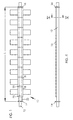
- a blender 10 for mixing electrostatographic developer is presented according to an aspect of the invention comprising a shaft 12 having a pair of stops 14 and 16 spaced along a length L.
- a plurality of blender segments 18 of the type for mixing electrostatographic developer are provided, each blender segment 18 having an aperture 20.
- the shaft 12 is received within the aperture 20 of each blender segment 18.
- a resilient spacer 22 is provided, the resilient spacer 22 and the plurality of blender segments 18 being compressed between the pair of stops 14 and 16.
- the resilient spacer 22 provides a greater degree of elastic compression than the blender segments 18 and compensates for variations in the width of the row of blender segments 18 induced by tolerance stack-up.
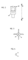
- Each blender segment 18 is manufactured to prescribed dimensions, each dimension having a tolerance. Of particular interest here, with reference to Figure 2, is the width W of each blender segment, and the tolerance dW associated with the width W.
- each blender segment 18 typically includes a small amount of variation in the manufactured width. Such variation is magnified when several blender segments 18 are placed in a row, a phenomena known as "tolerance stack-up.”
- the maximum variation in the total width of the row is the sum of the tolerances dW of each blender segment 18 (and the tolerances of any intermediate structures). Since the blender segments 18 are generally manufactured from a relatively incompressible material such as plastic or metal, the length L between the first and second stops 14 and 16 is set to approximately the greatest possible width of the stack. This ensures that all of the blender segments 18 will fit between the stops 14 and 16.
- the actual width of the row of blender segments 18 is usually less than the maximum possible width since the width of each blender segment 18 is usually less than the maximum allowed by the tolerances. If left uncompensated, the individual blender segments 18, after assembly of the blender 10, are able to move a small distance relative to the shaft and relative to each other. This residual looseness is undesirable.
- the resilient spacer 22 solves this problem by maintaining the blender segments 18 under compression over the relatively large variation in total width induced by tolerance stack-up, thus eliminating the residual looseness.
- the resilient spacer 22 may comprise a coil spring, a belleville washer, or other resilient structure that compensates for tolerance stack-up in the blender segments 18.
- the blender 10 is mounted in a developer sump and the shaft 12 is rotationally driven about its longitudinal axis.
- Examples of development apparatus that may implement a blender according to the present invention are described in United States Patents 4,634,286; 4,825,244; and 4,887,132. While not limited to any particular toner or developer, the present invention is particularly useful with two-component developer that implements a mixture of toner and carrier.
- Driving the blender 10 in a two-component developer induces tribocharging of the toner and carrier particles. The phenomena of tribocharging is well known in the electrostatographic arts.
- the blender segments may be configured in numerous ways, including knives, paddles, scoops, and/or ribbons, without limitation.
- the blender segments 18 are preferably driven by the shaft 12.
- the shaft 12 may have a key 13 that mates with the apertures 20 of the blender segments 18.
- the key 13 ensures rotation of the blender segments 18 with the shaft 12, although other geometries that render the shaft 12 and apertures 20 non-circular in cross section may be implemented.
- the blender segments 18 may be formed from any suitable material, including plastics and metals. They may be made by molding, casting, machining from bulk material, or any other suitable manufacturing processes for rendering geometries useful in a developer blender.
- the plurality of blender segments 18 are disposed in seriatim with the resilient spacer 22 adjacent one of the pair of stops 14 and 16, as presented in Figure 1.
- the resilient spacer 22 is immediately adjacent the stop 14.
- Blender 100 comprises a shaft 112 having a pair of stops 114 and 116 spaced along a length L.
- a plurality of blender segments 118 of the type for mixing electrostatographic developer are provided, each blender segment 118 having an aperture 120.
- the shaft 112 is received within the aperture 120 of each the blender segment 118.
- Resilient spacers 122 and 124 are provided, the resilient spacers 122 and 124 and the plurality of blender segments 118 being compressed between the pair of stops 114 and 116.
- the resilient spacer 122 is adjacent the stop 114
- the resilient spacer 124 is adjacent the stop 116.
- Wipers 115 may be provided immediately adjacent the stops 114 and 116, as presented in Figure 6.
- the shaft 112 may comprise a plurality of serrations 126, and one of the stops 114 comprises a snap ring 128 engaging one of the serrations 126.
- the other stop 116 may also comprise a snap ring 132 engaging a mating groove 134 in the shaft 112.
- the blender segments 118 form a ribbon blender
- the resilient spacer 122 comprises a plurality of stacked belleville washers 130.
- One or more additional spacers, such as resilient spacer 124, may also comprise a plurality of stacked belleville washers 130.
- the blender segments 118 may form a ribbon blender having a double helix 136 and 138.
- Various ribbon blenders that may be implemented in the practice of the present invention are described in United States Patent 4,634,286; 4,956,675; and 5,146,277.
- the blender segments 118 are of three general configurations; a first configuration 140 wherein helix 136 is outside helix 138, a second configuration 142 wherein helix 138 is outside 136, and a transition configuration 144 wherein the helixes 138 and 136 switch relative position.
- This geometry greatly enhances mixing of the developer, as described by United States Patent 4,634,286.
- each blender segment 18 comprises a ferrule 119 and an integral rib 121.
- the individual ribs 121 are aligned and form a rib that runs along the length of the blender segments 118.
- a method of fabricating a blender for mixing electrostatographic developer comprising disposing a resilient spacer 22 and a plurality of blender segments 18 of the type for mixing electrostatographic developer on a shaft 12, each blender segment 18 having an aperture 20, the shaft 12 being received within the aperture of each the blender segment 18, and compressing the resilient spacer 22 and the plurality of blender segments 18 between a pair of stops 114 and 116 on the shaft 112.
- the method may further comprise disposing the plurality of blender segments 18 in seriatim with the resilient spacer 22 adjacent one of the pair of stops 114 and 116.
- one of the stops may comprise a snap ring 128, and the method may further comprise pressing the snap ring 128 toward another of the stops into engagement with one of the plurality of serrations 126.
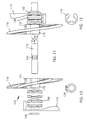
- blender 100 is fabricated by installing inserting the end of the shaft 112 into the apertures of the belleville washers 130 and the wiper 115. The snap ring 132 is then installed into a mating groove on the shaft 112. The blender segments 118 are installed onto the shaft from the opposite end. The belleville washers 130 on that end are then installed, followed by the wiper 115.
- the snap ring 128 is then installed on the shaft resting against the wiper 115.
- the entire assembly is then placed in a press that forces the snap ring 128 onto the serrations 126.
- a press having a load indicator is preferred in order to avoid overloading the assembly.
- the snap ring 128 may engage any one of the serrations 126, depending upon the prescribed load.
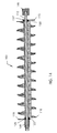
- FIG 14 a side-cross sectional view of the blender 100 is presented with tooling that may be employed to press snap ring 128 onto the serrations 126.
- the end of the shaft 112 proximate the snap ring 132 is placed in a cylindrical end-piece 146.
- the other end of the shaft 112 proximate the snap ring 128 is placed in a cylindrical end-piece 148, and is pressed toward the end-piece 146.
- the assembly may be placed in a lathe, for example, and the tail stock may be used to apply the force.
- the cylindrical end-piece 146 preferably does not contact the snap ring 132.
- a blender 100 has twenty-one (21) blender segments having a total nominal width of 14.7 inches. Allowable manufactured width, including tolerances, ranges from 14.616 inches to 14.784 inches (a range of 0.168 inches).
- Four belleville washers are stacked on each end, as shown in Figure 11, that provide a total deflection of 0.051 inches at a force of 150 Ibf.
- the length of the section having the serrations is 0.180 inches (three serrations at 0.060 inches per serration).
- the overall range of adjustment is the sum of 0.180 inches for the serrated section plus 0.051 inches for compression of the belleville washers. This provides more than sufficient adjustment for the 0.168 inches worst case variation due to tolerance stack-up.
Landscapes
- Chemical & Material Sciences (AREA)
- Chemical Kinetics & Catalysis (AREA)
- Physics & Mathematics (AREA)
- General Physics & Mathematics (AREA)
- Dry Development In Electrophotography (AREA)
- Accessories For Mixers (AREA)
- Wet Developing In Electrophotography (AREA)
- Mixers Of The Rotary Stirring Type (AREA)
Abstract
The invention relates generally to development apparatus for mixing and applying
developer material to a latent image on an image-bearing member in an
electrostatographic reproduction machine, such as a copier or printer. More
particularly, this invention relates to a blender (100) of the type for mixing
electrostatographic developer comprising a plurality of blender segments (118) mounted on
a shaft (112). A resilient spacer (122) is provided, according to an aspect of the invention,
wherein said resilient spacer and said plurality of blender segments are compressed
between said pair of stops (114,116). Residual looseness due to tolerance stack-up is
eliminated.
Description
- This invention relates generally to development apparatus for mixing and applying developer material to a latent image on an image-bearing member in an electrostatographic reproduction machine, such as a copier or printer. More particularly, this invention relates to a blender of the type for mixing electrostatographic developer comprising a plurality of blender segments mounted on a shaft.
- Development apparatus, for example a magnetic brush development apparatus, are well known for mixing and applying developer material to a latent electrostatic image on a photoconductor in an electrostatographic reproduction machine such as a copier or printer. Such a development apparatus typically includes an elongate housing which has a sump portion for containing the developer material. A two-component developer material comprises a mixture of carrier particles and toner particles. These particles are usually moved and mixed by a mixing device in the sump portion of the housing for triboelectrically charging the particles. Mixing also promotes uniformity in the concentration of toner particles throughout the sump portion, and in the distribution of developer material within the sump. The mixed and charged developer material can then be fed from the sump portion for development of the latent image on the photoconductor, which is generally a film or drum.
- The quality of such an image development depends, in significant part, on factors such as the level of charge on the toner particles achieved triboelectrically for example, and such as the level and uniformity of the concentration of toner particles in the developer material being applied. As is well known, these factors are mainly determined by the effectiveness of a mixing device used in the sump portion of the development apparatus housing for moving, mixing and charging the developer material particles.
- Certain prior blender assemblies implement a row of blender segments mounted on a shaft. Such assemblies typically exhibit a looseness in the blender segments after assembly due to tolerance stack-up. The segments are able to move small distance relative to the shaft and relative to each other. This movement, although limited, can cause toner flakes in the developer which, in turn, causes objectionable artifacts in the developed image. In addition, the outside diameter of certain blenders is ground during manufacturing to ensure an accurate fit with the developer housing. Looseness in the segments can cause the segments to chatter during the grinding operation.
- According to an aspect of the invention, a blender for mixing electrostatographic developer is provided, comprising a shaft having a pair of stops spaced along a length thereof, a plurality of blender segments of the type for mixing electrostatographic developer, each blender segment having an aperture, the shaft being received within the aperture of each blender segment, and a resilient spacer, wherein the resilient spacer and the plurality of blender segments are compressed between the pair of stops.
- According to a further aspect of the invention, a method of fabricating a blender for mixing electrostatographic developer is provided, comprising disposing a resilient spacer and a plurality of blender segments of the type for mixing electrostatographic developer on a shaft, each blender segment having an aperture, the shaft being received within the aperture of each blender segment, and compressing the resilient spacer and the plurality of blender between a pair of stops on the shaft.
- According to a still further aspect of the invention a blender for mixing electrostatographic developer is provided, comprising a shaft having a pair of stops spaced along a length thereof and a plurality of serrations, one of the stops comprising a snap ring engaging one of the serrations, a plurality of blender segments of the type for mixing electrostatographic developer, each blender segment having an aperture, the shaft being received within the aperture of each blender segment, and at least one belleville washer disposed immediately adjacent one of the stops, wherein the resilient spacer and the plurality of blender segments are compressed between the pair of stops.
- A blender according to the present invention has a plurality of blender segments exhibiting no residual looseness due to tolerance stack-up.
-
- Fig. 1
- presents a side view of a blender comprising a plurality of segments according to an aspect of the invention.
- Fig. 2
- presents a side view of a blender segment implemented in the blender of Figure 1, according to an aspect of the invention.
- Fig. 3
- presents an end view of a blender segment according to an aspect of the invention taken along line 3-3 of Figure 2.
- Fig. 4
- presents a side view of a shaft implemented in the blender of Figure 1.
- Fig. 5
- presents cross-section view of a shaft taken along line 5-5 of Figure 4.
- Fig. 6
- presents a side view of a blender comprising a plurality of segments according to a further aspect of the invention.
- Fig. 7
- presents side view of a blender segment according to an aspect of the invention.
- Fig. 8
- presents an end view of a blender segment according to an aspect of the invention taken along line 8-8 of Figure 7.
- Fig. 9
- presents a side view of the shaft implemented in the blender of Figure 6.
- Fig. 10
- presents a cross-sectional view of the shaft taken along line 10-10 of Figure 9.
- Fig. 11
- presents an enlarged exploded view of the blender of Figure 6 with parts broken away.
- Fig. 12
- presents a plan view of a snap ring implemented in the blender of Figure 6.
- Fig. 13
- presents a plan view of an e-ring implemented in the blender of Figure 6.
- Fig. 14
- presents a side cross-sectional view of the blender assembly with tooling for installing the snap ring.
- Various aspects of the invention are presented in Figures 1-14, which are not drawn to scale, and wherein like components are numbered alike. Referring now specifically to Figures 1-4, a
blender 10 for mixing electrostatographic developer is presented according to an aspect of the invention comprising ashaft 12 having a pair ofstops blender segments 18 of the type for mixing electrostatographic developer are provided, eachblender segment 18 having anaperture 20. Theshaft 12 is received within theaperture 20 of eachblender segment 18. Aresilient spacer 22 is provided, theresilient spacer 22 and the plurality ofblender segments 18 being compressed between the pair ofstops - According to an aspect of the invention, the
resilient spacer 22 provides a greater degree of elastic compression than theblender segments 18 and compensates for variations in the width of the row ofblender segments 18 induced by tolerance stack-up. Eachblender segment 18 is manufactured to prescribed dimensions, each dimension having a tolerance. Of particular interest here, with reference to Figure 2, is the width W of each blender segment, and the tolerance dW associated with the width W. - The tolerance dW may be expressed in numerous ways as an absolute positive or negative value, or as a positive/negative (+/-), in accordance with the particular tolerance system employed. In any event, each
blender segment 18 typically includes a small amount of variation in the manufactured width. Such variation is magnified whenseveral blender segments 18 are placed in a row, a phenomena known as "tolerance stack-up." - The maximum variation in the total width of the row is the sum of the tolerances dW of each blender segment 18 (and the tolerances of any intermediate structures). Since the
blender segments 18 are generally manufactured from a relatively incompressible material such as plastic or metal, the length L between the first andsecond stops blender segments 18 will fit between thestops - In practice, the actual width of the row of
blender segments 18 is usually less than the maximum possible width since the width of eachblender segment 18 is usually less than the maximum allowed by the tolerances. If left uncompensated, theindividual blender segments 18, after assembly of theblender 10, are able to move a small distance relative to the shaft and relative to each other. This residual looseness is undesirable. Theresilient spacer 22 solves this problem by maintaining theblender segments 18 under compression over the relatively large variation in total width induced by tolerance stack-up, thus eliminating the residual looseness. Theresilient spacer 22 may comprise a coil spring, a belleville washer, or other resilient structure that compensates for tolerance stack-up in theblender segments 18. - In a typical installation, the
blender 10 is mounted in a developer sump and theshaft 12 is rotationally driven about its longitudinal axis. Examples of development apparatus that may implement a blender according to the present invention are described in United States Patents 4,634,286; 4,825,244; and 4,887,132. While not limited to any particular toner or developer, the present invention is particularly useful with two-component developer that implements a mixture of toner and carrier. Driving theblender 10 in a two-component developer induces tribocharging of the toner and carrier particles. The phenomena of tribocharging is well known in the electrostatographic arts. The blender segments may be configured in numerous ways, including knives, paddles, scoops, and/or ribbons, without limitation. - The
blender segments 18 are preferably driven by theshaft 12. As best shown in Figure 5, theshaft 12 may have a key 13 that mates with theapertures 20 of theblender segments 18. The key 13 ensures rotation of theblender segments 18 with theshaft 12, although other geometries that render theshaft 12 andapertures 20 non-circular in cross section may be implemented. - The
blender segments 18 may be formed from any suitable material, including plastics and metals. They may be made by molding, casting, machining from bulk material, or any other suitable manufacturing processes for rendering geometries useful in a developer blender. - According to a preferred embodiment, the plurality of
blender segments 18 are disposed in seriatim with theresilient spacer 22 adjacent one of the pair ofstops resilient spacer 22 is immediately adjacent thestop 14. - Referring now to Figures 6-10, an embodiment of a
blender 100 for mixing electrostatographic developer is presented, according to a further aspect of the invention.Blender 100 comprises ashaft 112 having a pair ofstops blender segments 118 of the type for mixing electrostatographic developer are provided, eachblender segment 118 having anaperture 120. Theshaft 112 is received within theaperture 120 of each theblender segment 118.Resilient spacers resilient spacers blender segments 118 being compressed between the pair ofstops resilient spacer 122 is adjacent thestop 114, and theresilient spacer 124 is adjacent thestop 116.Wipers 115, or other structure, may be provided immediately adjacent thestops - According to a further aspect of the invention, the
shaft 112 may comprise a plurality ofserrations 126, and one of thestops 114 comprises asnap ring 128 engaging one of theserrations 126. Theother stop 116 may also comprise asnap ring 132 engaging amating groove 134 in theshaft 112. - According to a preferred embodiment, the
blender segments 118 form a ribbon blender, and theresilient spacer 122 comprises a plurality of stackedbelleville washers 130. One or more additional spacers, such asresilient spacer 124, may also comprise a plurality of stackedbelleville washers 130. Theblender segments 118 may form a ribbon blender having adouble helix - The
blender segments 118 are of three general configurations; afirst configuration 140 whereinhelix 136 isoutside helix 138, asecond configuration 142 whereinhelix 138 is outside 136, and atransition configuration 144 wherein thehelixes - Referring now specifically to Figures 7 and 8, each
blender segment 18 comprises aferrule 119 and anintegral rib 121. Referring again to Figure 6, theindividual ribs 121 are aligned and form a rib that runs along the length of theblender segments 118. - Referring again to Figures 1-4, a method of fabricating a blender for mixing electrostatographic developer is provided, according to a further aspect of the invention, comprising disposing a
resilient spacer 22 and a plurality ofblender segments 18 of the type for mixing electrostatographic developer on ashaft 12, eachblender segment 18 having anaperture 20, theshaft 12 being received within the aperture of each theblender segment 18, and compressing theresilient spacer 22 and the plurality ofblender segments 18 between a pair ofstops shaft 112. The method may further comprise disposing the plurality ofblender segments 18 in seriatim with theresilient spacer 22 adjacent one of the pair ofstops - Referring again to Figures 6-10, one of the stops, stop 114 for example, may comprise a
snap ring 128, and the method may further comprise pressing thesnap ring 128 toward another of the stops into engagement with one of the plurality ofserrations 126. - Referring now to Figure 11, an enlarged exploded view of
blender 100 with portions broken away is presented. Only theleft-most blender segment 118 and right-most blender segment of Figure 6 are presented in Figure 11 for the sake of clarity. According to a certain embodiment,snap ring 126 is configured as shown in Figure 12, andsnap ring 132 is configured as shown in Figure 13. Referring again to Figure 11,blender 100 is fabricated by installing inserting the end of theshaft 112 into the apertures of thebelleville washers 130 and thewiper 115. Thesnap ring 132 is then installed into a mating groove on theshaft 112. Theblender segments 118 are installed onto the shaft from the opposite end. The belleville washers 130 on that end are then installed, followed by thewiper 115. Thesnap ring 128 is then installed on the shaft resting against thewiper 115. The entire assembly is then placed in a press that forces thesnap ring 128 onto theserrations 126. A press having a load indicator is preferred in order to avoid overloading the assembly. Thesnap ring 128 may engage any one of theserrations 126, depending upon the prescribed load. - Referring now to Figure 14, a side-cross sectional view of the
blender 100 is presented with tooling that may be employed to presssnap ring 128 onto theserrations 126. The end of theshaft 112 proximate thesnap ring 132 is placed in a cylindrical end-piece 146. The other end of theshaft 112 proximate thesnap ring 128 is placed in a cylindrical end-piece 148, and is pressed toward the end-piece 146. The assembly may be placed in a lathe, for example, and the tail stock may be used to apply the force. The cylindrical end-piece 146 preferably does not contact thesnap ring 132. - In a certain embodiment, a
blender 100 has twenty-one (21) blender segments having a total nominal width of 14.7 inches. Allowable manufactured width, including tolerances, ranges from 14.616 inches to 14.784 inches (a range of 0.168 inches). Four belleville washers are stacked on each end, as shown in Figure 11, that provide a total deflection of 0.051 inches at a force of 150 Ibf. The length of the section having the serrations is 0.180 inches (three serrations at 0.060 inches per serration). The overall range of adjustment is the sum of 0.180 inches for the serrated section plus 0.051 inches for compression of the belleville washers. This provides more than sufficient adjustment for the 0.168 inches worst case variation due to tolerance stack-up. - Although the invention has been described and illustrated with reference to specific illustrative embodiments thereof, it is not intended that the invention be limited to those illustrative embodiments. Those skilled in the art will recognize that variations and modifications can be made without departing from the true scope and spirit of the invention as defined by the claims that follow. It is therefore intended to include within the invention all such variations and modifications as fall within the scope of the appended claims and equivalents thereof.
-
- 10
- blender
- 12
- shaft
- 13
- key
- 14
- stop
- 16
- stop
- 18
- blender segments
- 20
- aperture
- 22
- resilient spacer
- 100
- blender
- 112
- shaft
- 114
- stop
- 115
- wiper
- 116
- stop
- 118
- blender segments
- 119
- ferrule
- 120
- aperture
- 121
- rib
- 122
- resilient spacer
- 124
- resilient spacer
- 126
- serrations
- 128
- snap ring
- 130
- belleville washer
- 132
- snap ring
- 134
- groove
- 136
- double helix
- 138
- double helix
- 140
- first configuration
- 142
- second configuration
- 144
- transition configuration
- 146
- cylindrical end-piece
- 148
- cylindrical end-piece
- L
- length
- W
- width
- d W
- tolerance
Claims (17)
- A blender (10, 100) for mixing electrostatographic developer, comprising:a shaft (12,112) having a pair of stops (14, 16, 114, 116) spaced along a length thereof;a plurality of blender segments (18, 118) of the type for mixing electrostatographic developer, each said blender segment (18, 118) having an aperture (20, 120), said shaft (12, 112) being received within said aperture(20, 120) of each said blender segment (18, 118); and,a resilient spacer (22, 122), wherein said resilient spacer (22, 122) and said plurality of blender segments (18, 118) are compressed between said pair of stops (14, 16, 114, 116).
- The apparatus of claim 1, wherein said plurality of blender segments (18, 118) are disposed in seriatim with said resilient spacer (22, 122) adjacent one of said pair of stops (14, 16, 114, 116).
- The apparatus according to claims 1 or 2, wherein said resilient spacer (22, 122) is a spring.
- The apparatus according to one of claims 1, 2 or 3, wherein said resilient spacer (122) comprises at least one belleville washer (130).
- The apparatus according to one of claims 1 to 4, wherein said shaft (112) comprises a plurality of serrations (126), and one of said stops comprises a snap ring engaging one of said serrations (126).
- The apparatus according to one of claims 1 to 5, wherein said shaft (112) comprises a plurality of serrations (126), and one of said stops (114, 116) comprises a snap ring (128, 132) engaging one of said serrations (126), and said resilient spacer (122) is disposed adjacent said snap ring (128, 132).
- The apparatus according to one of claims 1 to 6, wherein said resilient spacer (112) comprises a plurality of stacked belleville washers (130).
- The apparatus according to one of claims 1 to 7, wherein said resilient spacer (122) is adjacent one of said pair of stops, (114, 116) and further comprising another resilient spacer (124) adjacent another of said pair of stops.
- The apparatus according to one of claims 1 to 8, wherein said blender segments (18, 118) form a ribbon blender.
- The apparatus according to one of claims 1 to 9, wherein said blender segments (18, 118) form a ribbon blender having a double helix (138).
- A method of fabricating a blender (10, 100) for mixing electrostatographic developer, comprising:disposing a resilient spacer (22, 122) and a plurality of blender segments (18, 118) of the type for mixing electrostatographic developer on a shaft, (12, 112) each said blender segment (18, 118) having an aperture (20,120), said shaft (12, 112) being received within said aperture (20,120) of each said blender segment; andcompressing said resilient spacer (22, 122) and said plurality of blender segments (18, 118) between a pair of stops (14, 16, 114, 116) on said shaft (12, 112).
- The method of claim 11, further comprising disposing said plurality of blender segments (18, 118) in seriatim with said resilient spacer (22, 122) adjacent one of said pair of stops (14, 16, 114, 116).
- The method of claims 11 or 12, wherein said shaft (112) comprises a plurality of serrations, and one of said stops comprises a snap ring (128), and further comprising pressing said snap ring (128) toward another of said stops (114, 116) into engagement with one of said plurality of serrations (126).
- The method of claim 13, further comprising disposing said resilient spacer (122) adjacent said snap ring (128).
- The method according to one of claims 11 to 14, wherein said resilient spacer comprises a plurality of stacked belleville washers (130).
- The method according to one of claims 11 to 15, wherein said resilient spacer is immediately adjacent one of said pair of stops, and further comprising another resilient spacer (132) immediately adjacent another of said pair of stops (114, 116).
- A blender (10, 100) for mixing electrostatographic developer, comprising:a shaft (12, 112) having a pair of stops (14, 16, 114, 116) spaced along a length thereof and a plurality of serrations (126), one of said stops comprising a snap ring (128) engaging one of said serrations (126);a plurality of blender segments (18, 118) of the type for mixing electrostatographic developer, each said blender segment having an aperture (20, 120), said shaft (12, 112) being received within said aperture of each said blender segment (18, 118); and,at least one belleville washer (130) disposed immediately adjacent one of said stops, wherein said resilient spacer (22, 122) and said plurality of blender segments are compressed between said pair of stops (14, 16, 114, 116).
Applications Claiming Priority (2)
| Application Number | Priority Date | Filing Date | Title |
|---|---|---|---|
| US20488000P | 2000-05-17 | 2000-05-17 | |
| US204880P | 2000-05-17 |
Publications (1)
| Publication Number | Publication Date |
|---|---|
| EP1156389A2 true EP1156389A2 (en) | 2001-11-21 |
Family
ID=22759851
Family Applications (1)
| Application Number | Title | Priority Date | Filing Date |
|---|---|---|---|
| EP01111155A Withdrawn EP1156389A2 (en) | 2000-05-17 | 2001-05-10 | Electrostatographic blender assembly and method |
Country Status (6)
| Country | Link |
|---|---|
| US (1) | US6585406B2 (en) |
| EP (1) | EP1156389A2 (en) |
| JP (1) | JP2003533747A (en) |
| AU (1) | AU2001259667A1 (en) |
| CA (1) | CA2374766A1 (en) |
| WO (1) | WO2001088627A1 (en) |
Cited By (1)
| Publication number | Priority date | Publication date | Assignee | Title |
|---|---|---|---|---|
| CN108067120A (en) * | 2016-11-14 | 2018-05-25 | 崔锦哲 | The mixing apparatus of animal manure and fertilizer composition |
Families Citing this family (11)
| Publication number | Priority date | Publication date | Assignee | Title |
|---|---|---|---|---|
| DK175687B1 (en) * | 2003-01-10 | 2005-01-17 | Tetra Laval Holdings & Finance | Transport auger for use as surface scraper in refrigeration and freezer units |
| US7137730B2 (en) * | 2003-09-26 | 2006-11-21 | Eastman Kodak Company | Electrographic ribbon blender and method |
| US7248823B2 (en) * | 2003-09-26 | 2007-07-24 | Eastman Kodak Company | Electrographic ribbon and method implementing a skive |
| US7426361B2 (en) * | 2005-09-01 | 2008-09-16 | Eastman Kodak Company | Developer mixing apparatus having four ribbon blenders |
| JP2007212845A (en) * | 2006-02-10 | 2007-08-23 | Murata Mach Ltd | Image forming apparatus |
| JP4985024B2 (en) * | 2007-03-28 | 2012-07-25 | 富士ゼロックス株式会社 | Rotating body for powder conveyance and toner cartridge |
| JP4947098B2 (en) * | 2009-07-02 | 2012-06-06 | 富士ゼロックス株式会社 | Conveying device, developer container, and image forming apparatus |
| JP4945659B2 (en) * | 2010-05-18 | 2012-06-06 | シャープ株式会社 | Developing device and image forming apparatus |
| US20130170875A1 (en) * | 2011-12-30 | 2013-07-04 | Rodney Evan Sproul | Toner vessel having improved paddle for breaking compacted toner |
| CN109205556B (en) * | 2018-09-17 | 2020-06-19 | 浙江工业职业技术学院 | Power preparation device of hydrogen energy power automobile |
| CN109179318B (en) * | 2018-09-20 | 2020-06-26 | 浙江工业职业技术学院 | A hydrogen energy-powered vehicle power preparation equipment that is easy to clean up waste |
Family Cites Families (21)
| Publication number | Priority date | Publication date | Assignee | Title |
|---|---|---|---|---|
| US2014636A (en) * | 1933-04-22 | 1935-09-17 | Universal Crusher Company | Conveyer |
| US2896925A (en) * | 1955-04-25 | 1959-07-28 | Daniel N Place | Mixing device |
| DE6915822U (en) * | 1969-04-19 | 1969-09-11 | Berstorff Gmbh Masch Hermann | MULTI-PIECE SCREW, IN PARTICULAR EXTRUDER SCREW |
| DE2252996A1 (en) * | 1972-10-28 | 1974-05-09 | Dierks & Soehne | MACHINE FOR CONTINUOUS MIXING AND PROCESSING OF POWDERY, GRAINY OR SMALL PIECES |
| JPS525652Y2 (en) * | 1973-10-26 | 1977-02-05 | ||
| US4077756A (en) * | 1976-09-08 | 1978-03-07 | Peerless Machine & Tool Corporation | Injection molding extrusion mixer |
| JPS5675315U (en) * | 1979-11-13 | 1981-06-19 | ||
| US4887132A (en) | 1984-04-06 | 1989-12-12 | Eastman Kodak Company | Electrographic development apparatus having a ribbon blender |
| US4610068A (en) * | 1985-07-17 | 1986-09-09 | Eastman Kodak Company | Method for forming a ribbon blender |
| US4634286A (en) | 1985-09-06 | 1987-01-06 | Eastman Kodak Company | Electrographic development apparatus having a continuous coil ribbon blender |
| EP0250793A3 (en) * | 1986-05-12 | 1989-07-12 | EASTMAN KODAK COMPANY (a New Jersey corporation) | Ribbon blender having a plurality of sections jointly forming ribbons |
| IT1208419B (en) * | 1987-04-29 | 1989-06-12 | Campagnolo Spa | CONTROL DEVICE OF THE SPEED CHANGE OF A BICYCLE |
| US4825244A (en) | 1987-11-23 | 1989-04-25 | Eastman Kodak Company | Development station with improved mixing and feeding apparatus |
| US4956675A (en) | 1988-12-23 | 1990-09-11 | Eastman Kodak Company | Ribbon blender for a development apparatus with self adjusting inner and outer ribbons |
| US5146277A (en) | 1991-09-20 | 1992-09-08 | Eastman Kodak Company | Dual-flow ribbon blender having interstream mixing member |
| US5310257A (en) * | 1992-10-29 | 1994-05-10 | Fluid Management Limited Partnership | Mixing apparatus |
| ATA105393A (en) * | 1993-06-01 | 1998-03-15 | Blach Josef Alois | MIXER FOR VISCOSE LIQUIDS AND MASS |
| IT1271271B (en) * | 1994-02-08 | 1997-05-27 | Fischer Georg Giessereianlagen | DEVICE FOR THE MIXING AND PREPARATION OF SLIDING MATERIALS |
| US5812916A (en) * | 1996-07-04 | 1998-09-22 | Mita Industrial Co., Ltd. | Conveyer device and toner cartridge equipped with conveyer device |
| JP3250094B2 (en) * | 1996-11-15 | 2002-01-28 | 京セラミタ株式会社 | Seal mechanism and container provided with the same |
| JPH1152693A (en) * | 1997-08-01 | 1999-02-26 | Sharp Corp | Developer processing equipment |
-
2001
- 2001-05-09 WO PCT/US2001/014950 patent/WO2001088627A1/en not_active Ceased
- 2001-05-09 AU AU2001259667A patent/AU2001259667A1/en not_active Abandoned
- 2001-05-09 JP JP2001584959A patent/JP2003533747A/en active Pending
- 2001-05-09 CA CA002374766A patent/CA2374766A1/en not_active Abandoned
- 2001-05-10 EP EP01111155A patent/EP1156389A2/en not_active Withdrawn
- 2001-05-11 US US09/853,725 patent/US6585406B2/en not_active Expired - Lifetime
Cited By (1)
| Publication number | Priority date | Publication date | Assignee | Title |
|---|---|---|---|---|
| CN108067120A (en) * | 2016-11-14 | 2018-05-25 | 崔锦哲 | The mixing apparatus of animal manure and fertilizer composition |
Also Published As
| Publication number | Publication date |
|---|---|
| CA2374766A1 (en) | 2001-11-22 |
| WO2001088627A1 (en) | 2001-11-22 |
| JP2003533747A (en) | 2003-11-11 |
| AU2001259667A1 (en) | 2001-11-26 |
| US6585406B2 (en) | 2003-07-01 |
| US20010046182A1 (en) | 2001-11-29 |
Similar Documents
| Publication | Publication Date | Title |
|---|---|---|
| US6585406B2 (en) | Electrostatographic blender assembly and method | |
| DE69327424T2 (en) | Procedure for installing a blade in the frame of a work unit | |
| DE69220195T2 (en) | Development device and process unit equipped with it | |
| KR100355723B1 (en) | Process cartridge, electrophotographic image forming apparatus, driving force transmission part and electrophotographic photosensitive drum | |
| KR100270672B1 (en) | Process cartridge, electrophotographic image forming apparatus, driving force transmitting member, and electrophotographic photosensitive drum | |
| US6226478B1 (en) | Process cartridge having drive mount for photosensitive drum | |
| KR100284825B1 (en) | Processing cartridge and electrophotographic image forming apparatus | |
| DE69320842T2 (en) | Charging part, charging device, process cartridge and image forming device | |
| WO2000016168A1 (en) | Driving mechanism for photosensitive image bearing drum in electrophotographic machines | |
| DE69816494T2 (en) | Charger with power supply unit | |
| EP1189116B1 (en) | Roller device for an image transferring device | |
| DE69504720T2 (en) | Development device for electrophotographic copier | |
| DE69616680T2 (en) | processor | |
| US5682587A (en) | Developing apparatus using hollow magnet roller | |
| EP0797125B1 (en) | Process cartridge and electrophotographic image forming apparatus | |
| EP1538489B1 (en) | Developing apparatus with a second toner supplying member | |
| DE69622603T2 (en) | Photoconductor unit with internal gear | |
| GB2397136A (en) | A toner cartridge | |
| US10248072B2 (en) | Cleaning roller provided with shaft and elastic body wound thereabout | |
| US5288152A (en) | Bearing for an electrophotographic apparatus | |
| EP0226454A2 (en) | A magnetic developer conveying device | |
| DE69523377T2 (en) | Magnetic roller and developing device | |
| JP3502534B2 (en) | Manufacturing method of magnet roll | |
| JP2003042178A (en) | Driving input member, coupling method of the same, and image formation device using the same | |
| DE4134106A1 (en) | ARRANGEMENT FOR AN ELECTRICAL CONNECTION OF A ROTATING COMPONENT WITH A CONNECTING CONTACT |
Legal Events
| Date | Code | Title | Description |
|---|---|---|---|
| PUAI | Public reference made under article 153(3) epc to a published international application that has entered the european phase |
Free format text: ORIGINAL CODE: 0009012 |
|
| AK | Designated contracting states |
Kind code of ref document: A2 Designated state(s): AT BE CH CY DE DK ES FI FR GB GR IE IT LI LU MC NL PT SE TR |
|
| AX | Request for extension of the european patent |
Free format text: AL;LT;LV;MK;RO;SI |
|
| RAP1 | Party data changed (applicant data changed or rights of an application transferred) |
Owner name: EASTMAN KODAK COMPANY |
|
| STAA | Information on the status of an ep patent application or granted ep patent |
Free format text: STATUS: THE APPLICATION IS DEEMED TO BE WITHDRAWN |
|
| 18D | Application deemed to be withdrawn |
Effective date: 20061201 |