EP1156360A1 - Ensemble d'affichage à inversion chromatique de contraste - Google Patents
Ensemble d'affichage à inversion chromatique de contraste Download PDFInfo
- Publication number
- EP1156360A1 EP1156360A1 EP00201733A EP00201733A EP1156360A1 EP 1156360 A1 EP1156360 A1 EP 1156360A1 EP 00201733 A EP00201733 A EP 00201733A EP 00201733 A EP00201733 A EP 00201733A EP 1156360 A1 EP1156360 A1 EP 1156360A1
- Authority
- EP
- European Patent Office
- Prior art keywords
- display
- polarizer
- display device
- state
- valve
- Prior art date
- Legal status (The legal status is an assumption and is not a legal conclusion. Google has not performed a legal analysis and makes no representation as to the accuracy of the status listed.)
- Granted
Links
Images

Classifications
-
- G—PHYSICS
- G02—OPTICS
- G02F—OPTICAL DEVICES OR ARRANGEMENTS FOR THE CONTROL OF LIGHT BY MODIFICATION OF THE OPTICAL PROPERTIES OF THE MEDIA OF THE ELEMENTS INVOLVED THEREIN; NON-LINEAR OPTICS; FREQUENCY-CHANGING OF LIGHT; OPTICAL LOGIC ELEMENTS; OPTICAL ANALOGUE/DIGITAL CONVERTERS
- G02F1/00—Devices or arrangements for the control of the intensity, colour, phase, polarisation or direction of light arriving from an independent light source, e.g. switching, gating or modulating; Non-linear optics
- G02F1/01—Devices or arrangements for the control of the intensity, colour, phase, polarisation or direction of light arriving from an independent light source, e.g. switching, gating or modulating; Non-linear optics for the control of the intensity, phase, polarisation or colour
- G02F1/13—Devices or arrangements for the control of the intensity, colour, phase, polarisation or direction of light arriving from an independent light source, e.g. switching, gating or modulating; Non-linear optics for the control of the intensity, phase, polarisation or colour based on liquid crystals, e.g. single liquid crystal display cells
- G02F1/133—Constructional arrangements; Operation of liquid crystal cells; Circuit arrangements
- G02F1/1333—Constructional arrangements; Manufacturing methods
- G02F1/1335—Structural association of cells with optical devices, e.g. polarisers or reflectors
- G02F1/133528—Polarisers
- G02F1/133536—Reflective polarizers
-
- G—PHYSICS
- G02—OPTICS
- G02F—OPTICAL DEVICES OR ARRANGEMENTS FOR THE CONTROL OF LIGHT BY MODIFICATION OF THE OPTICAL PROPERTIES OF THE MEDIA OF THE ELEMENTS INVOLVED THEREIN; NON-LINEAR OPTICS; FREQUENCY-CHANGING OF LIGHT; OPTICAL LOGIC ELEMENTS; OPTICAL ANALOGUE/DIGITAL CONVERTERS
- G02F1/00—Devices or arrangements for the control of the intensity, colour, phase, polarisation or direction of light arriving from an independent light source, e.g. switching, gating or modulating; Non-linear optics
- G02F1/01—Devices or arrangements for the control of the intensity, colour, phase, polarisation or direction of light arriving from an independent light source, e.g. switching, gating or modulating; Non-linear optics for the control of the intensity, phase, polarisation or colour
- G02F1/13—Devices or arrangements for the control of the intensity, colour, phase, polarisation or direction of light arriving from an independent light source, e.g. switching, gating or modulating; Non-linear optics for the control of the intensity, phase, polarisation or colour based on liquid crystals, e.g. single liquid crystal display cells
- G02F1/133—Constructional arrangements; Operation of liquid crystal cells; Circuit arrangements
- G02F1/1333—Constructional arrangements; Manufacturing methods
- G02F1/1335—Structural association of cells with optical devices, e.g. polarisers or reflectors
- G02F1/133528—Polarisers
- G02F1/133533—Colour selective polarisers
-
- G—PHYSICS
- G02—OPTICS
- G02F—OPTICAL DEVICES OR ARRANGEMENTS FOR THE CONTROL OF LIGHT BY MODIFICATION OF THE OPTICAL PROPERTIES OF THE MEDIA OF THE ELEMENTS INVOLVED THEREIN; NON-LINEAR OPTICS; FREQUENCY-CHANGING OF LIGHT; OPTICAL LOGIC ELEMENTS; OPTICAL ANALOGUE/DIGITAL CONVERTERS
- G02F1/00—Devices or arrangements for the control of the intensity, colour, phase, polarisation or direction of light arriving from an independent light source, e.g. switching, gating or modulating; Non-linear optics
- G02F1/01—Devices or arrangements for the control of the intensity, colour, phase, polarisation or direction of light arriving from an independent light source, e.g. switching, gating or modulating; Non-linear optics for the control of the intensity, phase, polarisation or colour
- G02F1/13—Devices or arrangements for the control of the intensity, colour, phase, polarisation or direction of light arriving from an independent light source, e.g. switching, gating or modulating; Non-linear optics for the control of the intensity, phase, polarisation or colour based on liquid crystals, e.g. single liquid crystal display cells
- G02F1/133—Constructional arrangements; Operation of liquid crystal cells; Circuit arrangements
- G02F1/1333—Constructional arrangements; Manufacturing methods
- G02F1/1347—Arrangement of liquid crystal layers or cells in which the final condition of one light beam is achieved by the addition of the effects of two or more layers or cells
- G02F1/13471—Arrangement of liquid crystal layers or cells in which the final condition of one light beam is achieved by the addition of the effects of two or more layers or cells in which all the liquid crystal cells or layers remain transparent, e.g. FLC, ECB, DAP, HAN, TN, STN, SBE-LC cells
-
- G—PHYSICS
- G04—HOROLOGY
- G04G—ELECTRONIC TIME-PIECES
- G04G9/00—Visual time or date indication means
- G04G9/0023—Visual time or date indication means by light valves in general
- G04G9/0029—Details
- G04G9/0035—Details constructional
-
- G—PHYSICS
- G02—OPTICS
- G02F—OPTICAL DEVICES OR ARRANGEMENTS FOR THE CONTROL OF LIGHT BY MODIFICATION OF THE OPTICAL PROPERTIES OF THE MEDIA OF THE ELEMENTS INVOLVED THEREIN; NON-LINEAR OPTICS; FREQUENCY-CHANGING OF LIGHT; OPTICAL LOGIC ELEMENTS; OPTICAL ANALOGUE/DIGITAL CONVERTERS
- G02F1/00—Devices or arrangements for the control of the intensity, colour, phase, polarisation or direction of light arriving from an independent light source, e.g. switching, gating or modulating; Non-linear optics
- G02F1/01—Devices or arrangements for the control of the intensity, colour, phase, polarisation or direction of light arriving from an independent light source, e.g. switching, gating or modulating; Non-linear optics for the control of the intensity, phase, polarisation or colour
- G02F1/13—Devices or arrangements for the control of the intensity, colour, phase, polarisation or direction of light arriving from an independent light source, e.g. switching, gating or modulating; Non-linear optics for the control of the intensity, phase, polarisation or colour based on liquid crystals, e.g. single liquid crystal display cells
- G02F1/133—Constructional arrangements; Operation of liquid crystal cells; Circuit arrangements
- G02F1/1333—Constructional arrangements; Manufacturing methods
- G02F1/1347—Arrangement of liquid crystal layers or cells in which the final condition of one light beam is achieved by the addition of the effects of two or more layers or cells
- G02F1/13471—Arrangement of liquid crystal layers or cells in which the final condition of one light beam is achieved by the addition of the effects of two or more layers or cells in which all the liquid crystal cells or layers remain transparent, e.g. FLC, ECB, DAP, HAN, TN, STN, SBE-LC cells
- G02F1/13473—Arrangement of liquid crystal layers or cells in which the final condition of one light beam is achieved by the addition of the effects of two or more layers or cells in which all the liquid crystal cells or layers remain transparent, e.g. FLC, ECB, DAP, HAN, TN, STN, SBE-LC cells for wavelength filtering or for colour display without the use of colour mosaic filters
Definitions
- the present invention relates to a display assembly for obtaining chromatic contrast inversion by means of two display devices superimposed comprising a first display at the front of which is a second display formed by a particular arrangement of fixed polarizers and cells with liquid crystals whose switching patterns control inversion chromatic.
- the invention also relates to a timepiece provided with such a display arrangement in which the first display is formed by the dial of said timepiece.
- the invention relates more particularly to such a timepiece in which the dial has an analog display of the current time on a background dark, the second display being provided to deliver other time information or non-hourly, said information can be observed in two colors different.
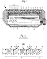
- the watch shown in FIG. 1, designated by the general reference 1, conventionally comprises a middle part 2, a base 3 and a crystal 20 delimiting together a box in the lower part of which are arranged a movement electronic clock 4 powered by a battery 5.
- the movement 4 includes a electronic timepiece circuit associated with a drive device (not shown), hands 12, 14 and 16, hours, minutes, seconds moving above a dial 18 carrying hour markers (not shown).
- Hands 12, 14 and 16 and dial 18 constitute the first device display, analog type in the example illustrated, designated by the reference general 22.
- This wristwatch 1 further comprises a second type display digital, designated by the general reference 24 and placed between the dial 18 and the crystal 20.
- the second display 24 is composed of a "sandwich" type structure comprising, from ice 20 to dial 18, an absorbing linear polarizer 40, a crystal display cell liquids 26, an absorbent linear polarizer 42 crossed with polarizer 40, a valve liquid crystal optics 28 and a reflective polarizer 44 crossed with polarizer 42.
- the switching states of the cell and the valve of the second display are controlled by a management unit 23 according to the manipulations carried out on at least one external control member 9.
- the display cell 26 conventionally comprises a front substrate 30 transparent, a rear substrate 32 also transparent and a sealing frame 34 forming spacing and closing means delimiting with the substrates 30 and 32 a closed cavity containing liquid crystals 27.
- the facing faces substrates 30 and 32 include transparent electrodes 36 respectively and 38 carried out for example in ITO.
- the rear electrode 38 extends over the entire surface of the substrate 32 and the front electrode 36 is configured in segments addressable separately by means of the management unit 23, the activated state (ON) or not activated (OFF) being symbolized by contactor 6 ( Figure 2).
- This cell 26 therefore allows alphanumeric characters to be displayed by passing the liquid crystal 27 from a transparent state to an absorbing state, or vice versa depending on the type of liquid crystal used.
- the optical valve 28, containing liquid crystals 29 and having a contactor 8 has a structure comparable to that of cell 26 and differs from it only in that the two transparent electrodes completely cover the opposite faces of the substrate upper 31 and lower substrate 33, so that the valve 28 can pass from a state fully transparent to a fully absorbent state, or vice versa depending on the type of liquid crystals used.
- the examples described in document EP 0 926 574 do not suggest, for the purpose of this invention, that two switching configurations.
- the OFF-OFF configuration shown in Figure 2
- the reader will easily understand following the path of the light rays through the polarizers 40, 42, 44 and intermediate cell 26 and valve 28 as the display dial analog 18 is visible, regardless of its light or dark shade.
- the display background consists of the reflective polarizer 44, due to the 90 ° rotation imparted by the valve 28 to the incident polarized light, and the display segments appear dark in due to the absorption by the polarizer 42 of the incident rays having undergone a rotation 90 ° by crossing said activated segments of cell 26, so that the second display appears dark on the mirror background.
- the object of the present invention is therefore to provide a particular arrangement allowing you to invert the color of the information displayed with another color, or that of the background on which it is displayed.
- the invention relates to a display assembly comprising a first display device at the front of which is disposed a second device active liquid crystal display.
- This second display device is characterized in that it includes, going from the outside to the first display a selective front polarizer of a first color, a matrix display cell or liquid crystal segments, a selective intermediate polarizer of a second color, an optical liquid crystal valve and a reflective rear polarizer if the first display has a dark background, and absorbing if the first display has a background clear.
- a management unit makes it possible to select two switching states of the cell and two valve switching states producing a reversal chromatic, either at the level of the information displayed, or at the level of the background on which said information is displayed.
- the display assembly when the cell is not switched (OFF state) by not delivering any information, and depending on the state of switching (ON / OFF) of the valve, the display assembly makes it possible to make visible only the first display or hide it completely with a mirror mask.
- this display assembly is particularly well suited to a wristwatch, because it is possible to have a OFF-OFF switching configuration consuming no energy and allowing to have permanently visible information of the current time on the first display, and to be able to display on request two other types information on the second display, easily differentiated by reversing chromatic.
- This information can be temporal quantities complementary to those given by the first display, or quantities not such as the values of sensor systems contained in the box of the timepiece.
- the construction of the display assembly according to the present invention is comparable to that which has been described with reference to FIG. 1 in the context of application to a wristwatch. However, it differs in that the polarizer front is a selective polarizer 11 of a first color "V", the polarizer intermediate is a selective polarizer 13 of a second color "R" and the polarizer rear is a reflective polarizer 15 if the first display, now designated by the reference 17 has a dark hue and an absorbing polarizer if the first display has a light shade. As indicated above, it therefore includes a unit of management 23 which, depending on the manipulations carried out on a control member outside 9, will control by means of the switch 6 of the valve 26 and the switch 8 of valve 28 the switching configurations.
- the intermediate polarizer 13 is crossed with the front polarizer 11 and the polarizer rear 15, the colors "V" and “R” being the complementary colors green and red, and the first display is constituted by a dial with analog shade display dark.
- the invention consists in surprisingly exploiting the imperfect character color selective polarizers both at the polarization level and at the selection of a specific color "V" or "R”, as briefly summarized below for a green selective polarizer.
- Unpolarized green monochromatic light passing through a polarizer selective green is generally polarized at 50% so that the light transmitted is reconstituted in non-polarized green light. If the incident light is polarized parallel to the polarization axis of the polarizer, it is transmitted to 100%. If it is polarized perpendicular to the axis of polarization, it is transmitted with the same polarization but with a strong attenuation of x%, which can be estimated at 5%.
- the light incident on the green selective polarizer is a light monochromatic red
- it is transmitted along the polarization axis of the polarizer with an attenuation of y% which can be estimated at 40%.
- the red light is polarized parallel to the green polarizer, it will be transmitted along the same axis of polarization with a weaker attenuation of z% which can be estimated at 80%. If the red light is polarized perpendicular to the green polarizer, we can consider that it is completely absorbed.
- the first display when it is dark in color, considers that it only reflects w% of the incident light, whatever its wavelength, this value can be estimated at 2%. When it is light in color, we can consider that it reflects light at 100%. We will finally consider that the reflective polarizer transmits whatever the wavelength 100% of the light polarized along its axis of polarization, and vice versa reflects 100% of the light perpendicularly polarized.
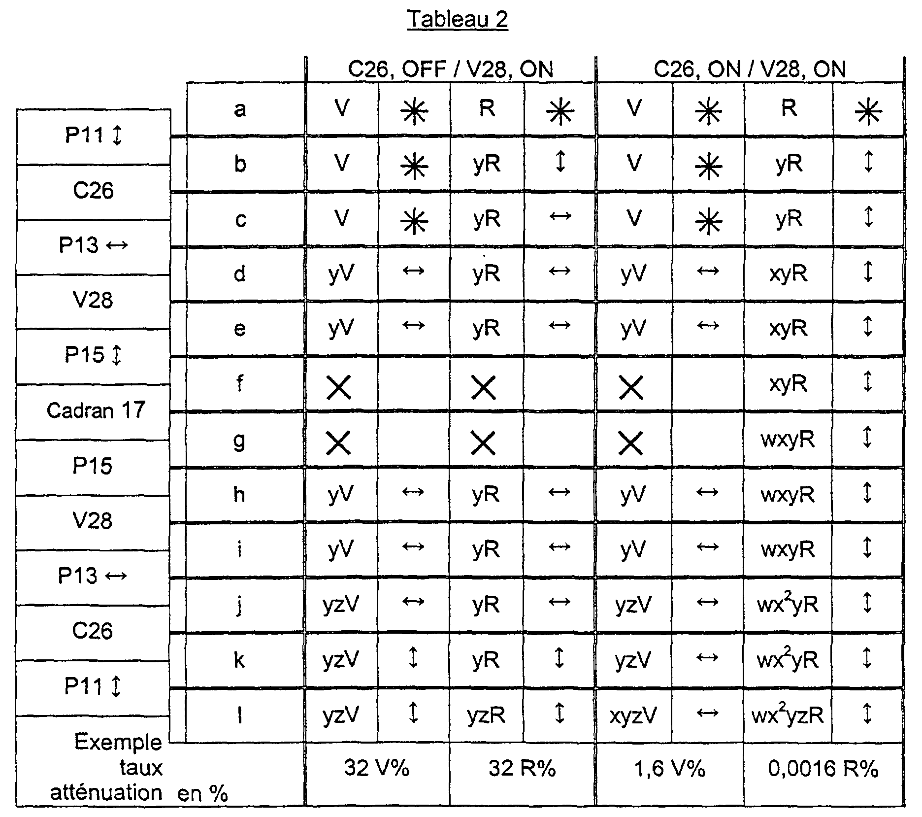
- the green color "V" is not modified up to the red selective polarizer P13 where it is horizontally polarized and attenuated by a coefficient y.
- the valve 28 has undergone a rotation of 90 ° and the green light is then polarized parallel to the axis of the reflective polarizer 15 which it crosses to strike the dial 17 and be reflected in the state g with a new attenuation w. It crosses a second time without modification the polarizer 15 then the valve 28 undergoing a new rotation of 90 °, so that it arrives in a state l with an axis of polarization parallel to that of the red selective polarizer 13 which it crosses by undergoing a new attenuation z.
- the valve 28 then the cell 26 will print two rotations of 90 ° so that the red component arrives parallel to the green selective polarizer 11 which it crosses undergoing a new attenuation z.
- the red component observable in state l can therefore be expressed by wyzR.
- the dark dial 17 which constitutes the first display device is visible as shown in FIG. 4.
- the OFF-ON switching configuration in which no information cannot be displayed by cell 26, corresponds to Figure 6 and the first two columns of Table 2. Following the path of the green component and the red component we see that the ON switching of the valve 28 directs the polarization of the two red and green components perpendicular to the axis of polarization of the reflective polarizer 15 so that they will both be reflected and be in state L with the same rate attenuation yz, that is to say, as indicated above, they will make it possible to recompose natural light. In this configuration, no information is displayed and the observer sees only a mirror background, which can be an effect sought after aesthetics, in particular in a timepiece.
- the ON-ON configuration corresponds to FIG. 7 and to the last two columns of table 2.
- the green component undergoes a first attenuation y in the state d , that it is reflected by the reflective polarizer 15, then that it undergoes successively two attenuations, z in state i and x in state l , so that the observable green component can be expressed by xyzV.
- the red component undergoes a succession of attenuations, including by the dark tint of the dial 17, so that the observable red component in l can be expressed by wx 2 yzR.
- the display assembly according to the invention makes it possible to swap the color of the information displayed by the second display from red to the green.
- the intermediate polarizer 13 selective of the red color is parallel both to the front polarizer 11 selective of the green color and to the rear polarizer 15 reflective.
- This construction is not the subject of a figure because it can easily be understood from the diagram of Figure 3, by simple rotation of the intermediate polarizer by 90 °.
- This embodiment makes it possible to obtain a chromatic inversion of the background on which the information of the second display is displayed, as is briefly explained with reference to Table 3 corresponding to two switching configurations OFF-OFF and ON-ON.
- the OFF-ON configuration provides a red background with the same attenuation coefficients in the ON-OFF state of example 1, and that the ON-OFF configuration of this embodiment, which has the same coefficients attenuation that the OFF-ON configuration of example 1 allows to create at the level of each activated segment of "windows" revealing a mirror background, so that the information delivered by the second display appears in clear on a red background.
- this embodiment allows a chromatic inversion of the background on which the information appears, passing from a switching configuration ON-ON to an ON-OFF configuration or vice versa.
- the selective intermediate polarizer 13 of the red color is parallel to the selective front polarizer 11 of green color, and crossed with the reflective rear polarizer 15.
- the front polarizer 11 is selective for the green color "V"
- the intermediate polarizer 13 is selective for the red color "R” by being crossed with the front polarizer 11
- the rear polarizer 15 is absorbent by being crossed with the intermediate polarizer 13 (that is to say parallel to the front polarizer 11)
- the first display is constituted by a dial 17 with analog display of light shade.
- the coefficient "w" of attenuation of the dial can be evaluated at the value 1 for a light shade.
- This construction is that represented in FIG. 3, and the chromatic inversion which it makes it possible to explain is explained with reference to Tables 4 and 5 below, in which the coefficient "w" of value 1 is not reported. .
- the two left columns correspond to the OFF-OFF switching configuration.
- the green component "V” undergoes attenuation y at d and attenuation z at i to be observable at l with a coefficient of attenuation yz.
- the red component "R” undergoes an attenuation y at b and an attenuation z at l so that it is observable with an attenuation yz.
- the two components having the same attenuation rate, natural light is reconstituted and the clear dial 17 is visible.
- the green component "V” In the ON-OFF configuration corresponding to the two right columns, the green component "V” corresponding to the two right columns, the green component “V” successively undergoes the attenuations y in d , z in i and x in l to appear at the observer with a xyz rate of attenuation.
- the red component undergoes attenuation y at b while being polarized parallel to the selective polarizer 11, then attenuation x at d .
- Its axis of polarization is rotated by 90 ° on e , so that it strikes the absorbing polarizer 15 perpendicular to its axis of polarization and that it is completely absorbed.
- the color green is the dominant color of the switched segments, therefore of the displayed information which appears in green on a light background of the dial.
- the two left columns correspond to the configuration of OFF-ON switching.
- the two green components "V” and red “R” arrive on the absorbing polarizer 15 with a polarization perpendicular to the polarization axis of said polarizer, so that they are both absorbed and that the background appears dark.
- the green component "V” is completely absorbed and the red component "R” undergoes an attenuation x 2 yz.
- the color red is the dominant color of the switched segments, therefore of the displayed information which appears in red on a dark background.
- This embodiment therefore allows, passing from a configuration of ON-OFF switching to an ON-ON configuration to have a chromatic inversion information displayed from green on a light background, to red on a dark background.
Landscapes
- Physics & Mathematics (AREA)
- Nonlinear Science (AREA)
- General Physics & Mathematics (AREA)
- Mathematical Physics (AREA)
- Chemical & Material Sciences (AREA)
- Crystallography & Structural Chemistry (AREA)
- Optics & Photonics (AREA)
- Electric Clocks (AREA)
- Liquid Crystal (AREA)
Abstract
Description
- la figure 1 est une vue en coupe d'une montre-bracelet comportant un ensemble d'affichage ayant deux affichages superposés,
- la figure 2 est une représentation schématique d'un mode de fonctionnement selon l'art antérieur,
- la figure 3 est le schéma explicatif d'un mode de fonctionnement selon l'invention,
- les figures 4 à 7 représentent schématiquement les quatre configurations de commutations possibles d'un ensemble d'affichage selon l'invention et les aspects visuels correspondants, et
- la figure 8 représente un mode de réalisation dans lequel une configuration de commutations permet d'obtenir une double inversion chromatique.



Claims (12)
- Ensemble d'affichage à inversion chromatique de contraste comprenant un premier dispositif d'affichage (22) à l'avant duquel est disposé un deuxième dispositif d'affichage (24) actif à cristaux liquides comprenant, en partant de l'extérieur, un polariseur avant (11), une cellule d'affichage (26) matriciel ou à segments à cristaux liquides LC1 ayant deux états (ON/OFF) de commutation, un polariseur intermédiaire (13), une valve optique (28) à cristaux liquides LC2 ayant au moins deux états (ON/OFF) de commutation et un polariseur arrière (15), les quatre configurations de commutation desdites cellule (26) et valve (28) étant déterminées par une unité de gestion (23), caractérisé en ce que dans le deuxième dispositif d'affichage (24), le polariseur avant (11) est sélectif d'une première couleur "V" le polariseur intermédiaire (13) est sélectif d'une deuxième couleur "R" et le polariseur arrière est réflectif lorsque le premier dispositif d'affichage (32) a un fond sombre et absorbant lorsque le premier dispositif d'affichage (22) a un fond clair, et en ce que l'unité de gestion (23) permet de sélectionner deux configurations de commutation permettant d'inverser la couleur de l'information affichée, ou celle du fond sur lequel ladite information est affichée.
- Ensemble d'affichage selon la revendication 1, caractérisé en ce que le polariseur intermédiaire (13) est croisé avec le polariseur avant (11) et le polariseur arrière (15), la cellule (26) est dans l'état ON et en ce que le changement d'état de la valve (28) d'un état ON à un état OFF, ou inversement, inverse les couleurs de l'information donnée par le deuxième affichage (24).
- Ensemble d'affichage selon la revendication 1, caractérisé en ce que les polariseurs avant (11), intermédiaire (13) et arrière (15) sont parallèles, la cellule (26) est dans l'état OFF et en ce que le changement d'état de la valve (28) d'un état ON à un état OFF, ou inversement, inverse les couleurs du fond sur lequel apparaissent les informations du deuxième affichage.
- Ensemble d'affichage selon l'une quelconque des revendications 1 à 3, caractérisé en ce que les première et deuxième couleurs "V", "G" des polariseurs sélectifs (11,13) sont des couleurs complémentaires.
- Ensemble d'affichage selon les revendications 2 ou 3, caractérisé en ce que les deux autres configurations de commutation permettent de rendre visible soit le premier affichage (22), soit de masquer totalement ledit premier affichage (22).
- Ensemble d'affichage selon la revendication 1, caractérisé en ce que la valve (28) comprend au moins deux zones distinctes ayant des configurations de commutation inversées permettant d'afficher deux types d'information en inversion chromatique.
- Ensemble d'affichage selon la revendication 1, caractérisé en ce que les cristaux liquides LC1 et LC2 sont de type nématique à hélice, indifféremment à anisotropie positive ou négative, en étant identiques ou différents dans la cellule et dans la valve.
- Ensemble d'affichage selon l'une quelconque des revendications 1 à 7, caractérisé en ce que le premier dispositif d'affichage (22) est choisi parmi un dispositif d'affichage analogique, un dispositif d'affichage digital et une combinaison de ces deux dispositifs pouvant en outre comporter un élément décoratif.
- Ensemble d'affichage selon la revendication 1, caractérisé en ce que le premier dispositif d'affichage (22) a, totalement ou partiellement, la même structure que celle du deuxième dispositif d'affichage (24).
- Pièce d'horlogerie comprenant une boíte fermée par une glace (20) et un fond (3) dans laquelle est logé un mouvement d'horlogerie associé à au moins un dispositif d'affichage selon l'une quelconque des revendications 1 à 9, ledit premier dispositif d'affichage (22) affichant essentiellement des grandeurs temporelles et ledit deuxième dispositif d'affichage (24) affichant des grandeurs temporelles complémentaires ou des grandeurs non temporelles de systèmes capteurs contenus dans la boíte de ladite pièce d'horlogerie.
- Pièce d'horlogerie selon la revendication 10, caractérisé en ce que le premier dispositif d'affichage (22) est de type analogique.
- Pièce d'horlogerie selon la revendication 10, caractérisé en ce que le deuxième dispositif (24) d'affichage est confondu avec la glace (20).
Priority Applications (1)
| Application Number | Priority Date | Filing Date | Title |
|---|---|---|---|
| EP00201733.3A EP1156360B1 (fr) | 2000-05-16 | 2000-05-16 | Ensemble d'affichage à inversion chromatique de contraste |
Applications Claiming Priority (1)
| Application Number | Priority Date | Filing Date | Title |
|---|---|---|---|
| EP00201733.3A EP1156360B1 (fr) | 2000-05-16 | 2000-05-16 | Ensemble d'affichage à inversion chromatique de contraste |
Publications (2)
| Publication Number | Publication Date |
|---|---|
| EP1156360A1 true EP1156360A1 (fr) | 2001-11-21 |
| EP1156360B1 EP1156360B1 (fr) | 2017-01-18 |
Family
ID=8171502
Family Applications (1)
| Application Number | Title | Priority Date | Filing Date |
|---|---|---|---|
| EP00201733.3A Expired - Lifetime EP1156360B1 (fr) | 2000-05-16 | 2000-05-16 | Ensemble d'affichage à inversion chromatique de contraste |
Country Status (1)
| Country | Link |
|---|---|
| EP (1) | EP1156360B1 (fr) |
Cited By (1)
| Publication number | Priority date | Publication date | Assignee | Title |
|---|---|---|---|---|
| EP4692960A1 (fr) | 2024-08-08 | 2026-02-11 | The Swatch Group Research and Development Ltd | Dispositif à cristaux liquides pour une pièce d'horlogerie |
Citations (5)
| Publication number | Priority date | Publication date | Assignee | Title |
|---|---|---|---|---|
| DE3034181A1 (de) * | 1980-09-11 | 1982-03-25 | Robert Bosch Gmbh, 7000 Stuttgart | Fluessigkristallzelle mit elektrisch umschaltbaren farben |
| EP0052000A2 (fr) * | 1980-11-10 | 1982-05-19 | Polaroid Corporation | Filtres de couleur variables |
| JPH11142837A (ja) * | 1997-09-03 | 1999-05-28 | Seiko Epson Corp | 表示素子及び電子時計 |
| EP0926574A1 (fr) * | 1997-12-22 | 1999-06-30 | Asulab S.A. | Ensemble d'affichage comprenant deux dispositifs d'affichage superposés |
| EP0930522A1 (fr) * | 1997-07-30 | 1999-07-21 | Citizen Watch Co., Ltd. | Affichage a cristaux liquides |
Family Cites Families (1)
| Publication number | Priority date | Publication date | Assignee | Title |
|---|---|---|---|---|
| WO1999032945A1 (fr) * | 1997-12-19 | 1999-07-01 | Asulab S.A. | Ensemble d'affichage comprenant deux dispositifs d'affichage superposes |
-
2000
- 2000-05-16 EP EP00201733.3A patent/EP1156360B1/fr not_active Expired - Lifetime
Patent Citations (5)
| Publication number | Priority date | Publication date | Assignee | Title |
|---|---|---|---|---|
| DE3034181A1 (de) * | 1980-09-11 | 1982-03-25 | Robert Bosch Gmbh, 7000 Stuttgart | Fluessigkristallzelle mit elektrisch umschaltbaren farben |
| EP0052000A2 (fr) * | 1980-11-10 | 1982-05-19 | Polaroid Corporation | Filtres de couleur variables |
| EP0930522A1 (fr) * | 1997-07-30 | 1999-07-21 | Citizen Watch Co., Ltd. | Affichage a cristaux liquides |
| JPH11142837A (ja) * | 1997-09-03 | 1999-05-28 | Seiko Epson Corp | 表示素子及び電子時計 |
| EP0926574A1 (fr) * | 1997-12-22 | 1999-06-30 | Asulab S.A. | Ensemble d'affichage comprenant deux dispositifs d'affichage superposés |
Non-Patent Citations (1)
| Title |
|---|
| PATENT ABSTRACTS OF JAPAN vol. 1999, no. 10 31 August 1999 (1999-08-31) * |
Cited By (1)
| Publication number | Priority date | Publication date | Assignee | Title |
|---|---|---|---|---|
| EP4692960A1 (fr) | 2024-08-08 | 2026-02-11 | The Swatch Group Research and Development Ltd | Dispositif à cristaux liquides pour une pièce d'horlogerie |
Also Published As
| Publication number | Publication date |
|---|---|
| EP1156360B1 (fr) | 2017-01-18 |
Similar Documents
| Publication | Publication Date | Title |
|---|---|---|
| EP1128240B1 (fr) | Ensemble d'affichage à inversion de constrate comprenant deux dispositifs d'affichage superposés | |
| EP1040391B1 (fr) | Ensemble d'affichage comprenant deux dispositifs d'affichage superposes | |
| EP0078237B1 (fr) | Montre à dispositif d'affichage analogique dont le cadran est formé par une cellule d'affichage à cristal liquide | |
| EP0786685B1 (fr) | Dispositif d'affichage d'un décor et pièce d'horlogerie le comprenant | |
| EP0872759B1 (fr) | Dispositif d'affichage à cristaux liquides destiné notamment à former un écran d'affichage d'images en couleur | |
| EP3049862A1 (fr) | Filtre optique adaptatif pour verre de lunettes | |
| EP3839617B1 (fr) | Dispositif d affichage à cristaux liquides | |
| EP3650958A1 (fr) | Objet muni d'un dispositif d'affichage electrooptique | |
| EP2185979B1 (fr) | Piece d'horlogerie a affichage modulable | |
| US6678217B2 (en) | Display assembly with chromatic contrast inversion | |
| FR2480952A1 (fr) | Cellule d'affichage electro-optique passif | |
| WO2012175250A1 (fr) | Afficheur a cristal liquide a electrodes d'effacement | |
| EP1189095A1 (fr) | Ensemble d'affichage bicolore à cristaux liquides | |
| EP1156360B1 (fr) | Ensemble d'affichage à inversion chromatique de contraste | |
| EP0939331B1 (fr) | Ensemble d'affichage comprenant deux dispositifs d'affichage superposés | |
| EP0926574A1 (fr) | Ensemble d'affichage comprenant deux dispositifs d'affichage superposés | |
| EP0792474B1 (fr) | Dispositif d'affichage a cristal liquide utilisant des films birefringents | |
| WO2006048564A1 (fr) | Afficheur ophtalmique comportant une lentille ophtalmique et un imageur optique | |
| FR2473744A1 (fr) | Montre electronique comportant un dispositif d'affichage electrochroique | |
| EP1085364B1 (fr) | Ensemble d'affichage comprenant deux dispositifs d'affichage superposés | |
| FR2461315A1 (fr) | Cellule d'affichage electro-optique | |
| EP1174756B1 (fr) | Ensemble d'affichage comportant une cellule électro-optique et une cellule photovoltaique | |
| FR2646269A1 (fr) | Cellule d'affichage electro-optique perfectionnee | |
| CH716960A2 (fr) | Dispositif d'affichage à cristaux liquides. | |
| EP1202109A1 (fr) | Dispositif d'affichage à cristaux liquides à coefficient de réflexion de la lumière élevé |
Legal Events
| Date | Code | Title | Description |
|---|---|---|---|
| PUAI | Public reference made under article 153(3) epc to a published international application that has entered the european phase |
Free format text: ORIGINAL CODE: 0009012 |
|
| AK | Designated contracting states |
Kind code of ref document: A1 Designated state(s): AT BE CH CY DE DK ES FI FR GB GR IE IT LI LU MC NL PT SE |
|
| AX | Request for extension of the european patent |
Free format text: AL;LT;LV;MK;RO;SI |
|
| 17P | Request for examination filed |
Effective date: 20020521 |
|
| AKX | Designation fees paid |
Free format text: AT BE CH CY DE DK ES FI FR GB GR IE IT LI LU MC NL PT SE |
|
| RAP1 | Party data changed (applicant data changed or rights of an application transferred) |
Owner name: ASULAB S.A. |
|
| 17Q | First examination report despatched |
Effective date: 20091218 |
|
| GRAP | Despatch of communication of intention to grant a patent |
Free format text: ORIGINAL CODE: EPIDOSNIGR1 |
|
| INTG | Intention to grant announced |
Effective date: 20161107 |
|
| GRAS | Grant fee paid |
Free format text: ORIGINAL CODE: EPIDOSNIGR3 |
|
| GRAA | (expected) grant |
Free format text: ORIGINAL CODE: 0009210 |
|
| AK | Designated contracting states |
Kind code of ref document: B1 Designated state(s): AT BE CH CY DE DK ES FI FR GB GR IE IT LI LU MC NL PT SE |
|
| REG | Reference to a national code |
Ref country code: GB Ref legal event code: FG4D Free format text: NOT ENGLISH |
|
| REG | Reference to a national code |
Ref country code: CH Ref legal event code: EP |
|
| REG | Reference to a national code |
Ref country code: CH Ref legal event code: NV Representative=s name: ICB INGENIEURS CONSEILS EN BREVETS SA, CH Ref country code: AT Ref legal event code: REF Ref document number: 863238 Country of ref document: AT Kind code of ref document: T Effective date: 20170215 |
|
| REG | Reference to a national code |
Ref country code: IE Ref legal event code: FG4D Free format text: LANGUAGE OF EP DOCUMENT: FRENCH |
|
| REG | Reference to a national code |
Ref country code: DE Ref legal event code: R096 Ref document number: 60049529 Country of ref document: DE |
|
| REG | Reference to a national code |
Ref country code: NL Ref legal event code: MP Effective date: 20170118 |
|
| REG | Reference to a national code |
Ref country code: AT Ref legal event code: MK05 Ref document number: 863238 Country of ref document: AT Kind code of ref document: T Effective date: 20170118 |
|
| PG25 | Lapsed in a contracting state [announced via postgrant information from national office to epo] |
Ref country code: NL Free format text: LAPSE BECAUSE OF FAILURE TO SUBMIT A TRANSLATION OF THE DESCRIPTION OR TO PAY THE FEE WITHIN THE PRESCRIBED TIME-LIMIT Effective date: 20170118 |
|
| PG25 | Lapsed in a contracting state [announced via postgrant information from national office to epo] |
Ref country code: FI Free format text: LAPSE BECAUSE OF FAILURE TO SUBMIT A TRANSLATION OF THE DESCRIPTION OR TO PAY THE FEE WITHIN THE PRESCRIBED TIME-LIMIT Effective date: 20170118 Ref country code: GR Free format text: LAPSE BECAUSE OF FAILURE TO SUBMIT A TRANSLATION OF THE DESCRIPTION OR TO PAY THE FEE WITHIN THE PRESCRIBED TIME-LIMIT Effective date: 20170419 |
|
| PG25 | Lapsed in a contracting state [announced via postgrant information from national office to epo] |
Ref country code: SE Free format text: LAPSE BECAUSE OF FAILURE TO SUBMIT A TRANSLATION OF THE DESCRIPTION OR TO PAY THE FEE WITHIN THE PRESCRIBED TIME-LIMIT Effective date: 20170118 Ref country code: ES Free format text: LAPSE BECAUSE OF FAILURE TO SUBMIT A TRANSLATION OF THE DESCRIPTION OR TO PAY THE FEE WITHIN THE PRESCRIBED TIME-LIMIT Effective date: 20170118 Ref country code: PT Free format text: LAPSE BECAUSE OF FAILURE TO SUBMIT A TRANSLATION OF THE DESCRIPTION OR TO PAY THE FEE WITHIN THE PRESCRIBED TIME-LIMIT Effective date: 20170518 Ref country code: AT Free format text: LAPSE BECAUSE OF FAILURE TO SUBMIT A TRANSLATION OF THE DESCRIPTION OR TO PAY THE FEE WITHIN THE PRESCRIBED TIME-LIMIT Effective date: 20170118 Ref country code: LU Free format text: LAPSE BECAUSE OF NON-PAYMENT OF DUE FEES Effective date: 20170531 |
|
| REG | Reference to a national code |
Ref country code: DE Ref legal event code: R097 Ref document number: 60049529 Country of ref document: DE |
|
| PG25 | Lapsed in a contracting state [announced via postgrant information from national office to epo] |
Ref country code: IT Free format text: LAPSE BECAUSE OF FAILURE TO SUBMIT A TRANSLATION OF THE DESCRIPTION OR TO PAY THE FEE WITHIN THE PRESCRIBED TIME-LIMIT Effective date: 20170118 |
|
| PLBE | No opposition filed within time limit |
Free format text: ORIGINAL CODE: 0009261 |
|
| STAA | Information on the status of an ep patent application or granted ep patent |
Free format text: STATUS: NO OPPOSITION FILED WITHIN TIME LIMIT |
|
| PG25 | Lapsed in a contracting state [announced via postgrant information from national office to epo] |
Ref country code: DK Free format text: LAPSE BECAUSE OF FAILURE TO SUBMIT A TRANSLATION OF THE DESCRIPTION OR TO PAY THE FEE WITHIN THE PRESCRIBED TIME-LIMIT Effective date: 20170118 |
|
| REG | Reference to a national code |
Ref country code: DE Ref legal event code: R119 Ref document number: 60049529 Country of ref document: DE |
|
| 26N | No opposition filed |
Effective date: 20171019 |
|
| GBPC | Gb: european patent ceased through non-payment of renewal fee |
Effective date: 20170516 |
|
| PG25 | Lapsed in a contracting state [announced via postgrant information from national office to epo] |
Ref country code: MC Free format text: LAPSE BECAUSE OF FAILURE TO SUBMIT A TRANSLATION OF THE DESCRIPTION OR TO PAY THE FEE WITHIN THE PRESCRIBED TIME-LIMIT Effective date: 20170118 |
|
| REG | Reference to a national code |
Ref country code: IE Ref legal event code: MM4A |
|
| REG | Reference to a national code |
Ref country code: FR Ref legal event code: ST Effective date: 20180131 |
|
| PG25 | Lapsed in a contracting state [announced via postgrant information from national office to epo] |
Ref country code: LU Free format text: LAPSE BECAUSE OF NON-PAYMENT OF DUE FEES Effective date: 20170516 |
|
| REG | Reference to a national code |
Ref country code: BE Ref legal event code: MM Effective date: 20170531 |
|
| PG25 | Lapsed in a contracting state [announced via postgrant information from national office to epo] |
Ref country code: GB Free format text: LAPSE BECAUSE OF NON-PAYMENT OF DUE FEES Effective date: 20170516 Ref country code: DE Free format text: LAPSE BECAUSE OF NON-PAYMENT OF DUE FEES Effective date: 20171201 Ref country code: IE Free format text: LAPSE BECAUSE OF NON-PAYMENT OF DUE FEES Effective date: 20170516 |
|
| PG25 | Lapsed in a contracting state [announced via postgrant information from national office to epo] |
Ref country code: FR Free format text: LAPSE BECAUSE OF NON-PAYMENT OF DUE FEES Effective date: 20170531 |
|
| PG25 | Lapsed in a contracting state [announced via postgrant information from national office to epo] |
Ref country code: BE Free format text: LAPSE BECAUSE OF NON-PAYMENT OF DUE FEES Effective date: 20170531 |
|
| PGFP | Annual fee paid to national office [announced via postgrant information from national office to epo] |
Ref country code: CH Payment date: 20190419 Year of fee payment: 20 |
|
| PG25 | Lapsed in a contracting state [announced via postgrant information from national office to epo] |
Ref country code: CY Free format text: LAPSE BECAUSE OF NON-PAYMENT OF DUE FEES Effective date: 20170118 |
|
| REG | Reference to a national code |
Ref country code: CH Ref legal event code: PL |