EP1156344A2 - MR imaging method and MRI apparatus - Google Patents
MR imaging method and MRI apparatus Download PDFInfo
- Publication number
- EP1156344A2 EP1156344A2 EP01304217A EP01304217A EP1156344A2 EP 1156344 A2 EP1156344 A2 EP 1156344A2 EP 01304217 A EP01304217 A EP 01304217A EP 01304217 A EP01304217 A EP 01304217A EP 1156344 A2 EP1156344 A2 EP 1156344A2
- Authority
- EP
- European Patent Office
- Prior art keywords
- view
- addition
- till
- value
- phase encoding
- Prior art date
- Legal status (The legal status is an assumption and is not a legal conclusion. Google has not performed a legal analysis and makes no representation as to the accuracy of the status listed.)
- Ceased
Links
Images



Classifications
-
- G—PHYSICS
- G01—MEASURING; TESTING
- G01R—MEASURING ELECTRIC VARIABLES; MEASURING MAGNETIC VARIABLES
- G01R33/00—Arrangements or instruments for measuring magnetic variables
- G01R33/20—Arrangements or instruments for measuring magnetic variables involving magnetic resonance
- G01R33/44—Arrangements or instruments for measuring magnetic variables involving magnetic resonance using nuclear magnetic resonance [NMR]
- G01R33/48—NMR imaging systems
- G01R33/4818—MR characterised by data acquisition along a specific k-space trajectory or by the temporal order of k-space coverage, e.g. centric or segmented coverage of k-space
- G01R33/482—MR characterised by data acquisition along a specific k-space trajectory or by the temporal order of k-space coverage, e.g. centric or segmented coverage of k-space using a Cartesian trajectory
-
- G—PHYSICS
- G01—MEASURING; TESTING
- G01R—MEASURING ELECTRIC VARIABLES; MEASURING MAGNETIC VARIABLES
- G01R33/00—Arrangements or instruments for measuring magnetic variables
- G01R33/20—Arrangements or instruments for measuring magnetic variables involving magnetic resonance
- G01R33/44—Arrangements or instruments for measuring magnetic variables involving magnetic resonance using nuclear magnetic resonance [NMR]
- G01R33/48—NMR imaging systems
- G01R33/54—Signal processing systems, e.g. using pulse sequences ; Generation or control of pulse sequences; Operator console
- G01R33/56—Image enhancement or correction, e.g. subtraction or averaging techniques, e.g. improvement of signal-to-noise ratio and resolution
-
- G—PHYSICS
- G01—MEASURING; TESTING
- G01R—MEASURING ELECTRIC VARIABLES; MEASURING MAGNETIC VARIABLES
- G01R33/00—Arrangements or instruments for measuring magnetic variables
- G01R33/20—Arrangements or instruments for measuring magnetic variables involving magnetic resonance
- G01R33/44—Arrangements or instruments for measuring magnetic variables involving magnetic resonance using nuclear magnetic resonance [NMR]
- G01R33/48—NMR imaging systems
- G01R33/54—Signal processing systems, e.g. using pulse sequences ; Generation or control of pulse sequences; Operator console
- G01R33/56—Image enhancement or correction, e.g. subtraction or averaging techniques, e.g. improvement of signal-to-noise ratio and resolution
- G01R33/5608—Data processing and visualization specially adapted for MR, e.g. for feature analysis and pattern recognition on the basis of measured MR data, segmentation of measured MR data, edge contour detection on the basis of measured MR data, for enhancing measured MR data in terms of signal-to-noise ratio by means of noise filtering or apodization, for enhancing measured MR data in terms of resolution by means for deblurring, windowing, zero filling, or generation of gray-scaled images, colour-coded images or images displaying vectors instead of pixels
Definitions
- the present invention relates to an MR imaging method and an MRI (Magnetic Resonance Imaging) apparatus, and more particularly to an MR imaging method and an MRI apparatus capable of improving picture quality without increasing the number of times of data collection and restraining artifacts resulting from differences in noise structure between parts differing in the number of times of addition.
- MRI Magnetic Resonance Imaging
- the number of times of addition Xn may be constant all the time as illustrated in Fig. 1, varied linearly to become greater as the absolute value of the quantity of phase encoding decreases as illustrated in Fig. 2, or varied stepwise to become greater as the absolute value of the quantity of phase encoding decreases as illustrated in Fig. 3.
- the present invention seeks to provide an MR imaging method and an MRI apparatus capable of improving picture quality without increasing the overall number of times of data collection and restraining artifacts resulting from differences in noise structure between parts differing in the number of times of addition.
- the invention provides an MR imaging method whereby k spaces are configured out of views from the first view, where the quantity of phase encoding takes on the largest negative (or positive) value, through a Vth view, where the quantity of phase encoding takes on the largest positive (or negative) value, and data
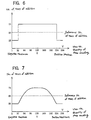
- the above-described MR imaging method can improve picture quality without increasing the overall number of times of data collection because the number of times of addition Xn is varied to become greater as the absolute value of the quantity of phase encoding decreases and to cause all or part of it to follow either a Hamming function or a Hanning function, and accordingly the number of times of addition is increased not only in the view where the absolute value of the quantity of phase encoding is "0" but also in neighboring views. Moreover, since the variation in the number of times of addition is continuous, artifacts resulting from differences in noise structure between parts differing in the number of times of addition can be restrained.
- the invention provides an MR imaging method whereby k spaces are configured out of views from the first view, where the quantity of phase encoding takes on the largest negative (or positive) value, through a Vth view, where the quantity of phase encoding takes on the largest positive (or negative) value, and data
- the total number of views V is equally divided into eight, and the areas of the two ends of each V/8, where the absolute value of the quantity of phase encoding is the greatest, are reduced in the number of times of addition by 1/2 of the reference number of times N, because their contributions to picture quality is small.
- the remaining middle 6V/8 areas are increased in the number of times of addition by 1/2 of the reference number of times N, because their contributions to picture quality are great, and further to alleviate the non-continuity of the variations of the number of times of addition, the number of times of addition is varied so as to follow either a Hamming function or a Hanning function.
- the invention provides an MR imaging method whereby k spaces are configured out of views from the first view, where the quantity of phase encoding takes on the largest negative (or positive) value, through a Vth view, where the quantity of phase encoding takes on the largest positive (or negative) value, and data
- the total number of views V is equally divided into eight, and the areas of the two ends of each V/8, where the absolute value of the quantity of phase encoding is the greatest, are reduced in the number of times of addition by 1/2 of the reference number of times N, because their contributions to picture quality is small.
- the remaining middle 6V/8 areas are increased in the number of times of addition by 1/2 of the reference number of times N, because their contributions to picture quality are great.
- the areas in which the number of times of addition has been reduced by 1/2 of the reference number of times N and the areas in which the number of times of addition has been increased by 1/2 of the reference number of times N are linked by a straight line to equalize the overall number of times of addition.
- the number of times of addition in the middle 6V/8 areas is varied so as to follow either a Hamming function or a Hanning function.
- the variation in the number of times of addition is continuous in the part from the (V/8+1)-th view till the (V-V/8)-th view, whose contributions to picture quality are great, artifacts resulting from differences in noise structure between parts differing in the number of times of addition can be restrained.
- the above-described MRI apparatus according to the fourth aspect of the invention can appropriately implement the MR imaging method according to the first aspect described above.
- the above-described MRI apparatus according to the fifth aspect of the invention can appropriately implement the MR imaging method according to the second aspect described above.
- the above-described MRI apparatus according to the sixth aspect of the invention can appropriately implement the MR imaging method according to the third aspect described above.
- Fig. 4 is a block diagram of an MRI apparatus in the first mode of implementing the invention.
- a magnet assembly 1 has within it a void part (hole) into which a sample is to be inserted and, surrounding this void part, there are arranged a static magnetic field coil 1p; a gradient magnetic field coil 1g for generating the gradient magnetic filed of a slice axis, a lead axis and a phase axis; a transmission coil 1t for providing an RF pulse for exciting atomic nucleus spins within the sample; and a reception coil 1r for detecting an NMR signal from the sample.
- These static magnetic field coil 1p, gradient magnetic field coil 1g, transmission coil 1t and reception coil 1r are respectively connected to a static magnetic field power source 2, a gradient magnetic field drive circuit 3, an RF power amplifier 4 and a preliminary amplifier 5.
- a permanent magnet may be used in place of the static magnetic field coil 1p.
- a sequence memory circuit 6, in accordance with an instruction from a computer 7, operates the gradient magnetic field drive circuit 3 on the basis of a pulse sequence stored in it, generates a gradient magnetic field from the gradient magnetic field coil 1g of the aforementioned magnet assembly 1 and, at the same time, operates a gate modulation circuit 8 to modulate the carrier output signal of an RF oscillator circuit 9 into a pulse-shaped signal of a prescribed timing in a prescribed envelope form, applies it as an RF pulse to the RF power amplifier 4 and, after its power amplification by the RF power amplifier 4, applies it to the transmission coil 1t of the aforementioned magnet assembly 1 to selectively excite a desired slice area.
- the preliminary amplifier 5 amplifies the NMR signal from the sample, detected by the reception coil 1r of the magnet assembly 1, and inputs it to a phase detector 10.
- the phase detector 10 with the carrier output signal of the RF oscillator circuit 9 as its reference signal, phase-detects the NMR signal from the preliminary amplifier 5, and provides it to an A/D converter 11.
- the A/D converter 11 converts the phase-detected analog signal into a digital signal, and inputs it to the computer 7.
- the computer 7 reads data from the A/D converter 11, carries out an operation to reconfigure an image, and generates an image of a desired slice area.
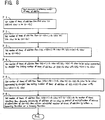
- the computer 7 further executes processing to determine the number of times of addition shown in Fig. 5 to determine the number of times of addition Xn. It is responsible for over all control, further including reception of information inputted from an operation console 12.
- a display apparatus 13 carries out displaying of the aforementioned image among other things.
- Fig. 5 is a flowchart of processing to determination of the number of times of addition pertaining to the present invention.
- the above-described MRI apparatus 100 reduces the number of times of addition Xn in parts where the absolute value of the quantity of phase encoding is large, which little contribute to picture quality, and increases the number of times of addition Xn in parts where the absolute value of the quantity of phase encoding is small, which greatly contribute to picture quality.
- the number of times of addition Xn is increased not only in the part where the absolute value of the quantity of phase encoding is "0" but also in its vicinities. Therefore, picture quality can be efficiently improved without increasing the overall number of times of data collection.
Landscapes
- Physics & Mathematics (AREA)
- General Physics & Mathematics (AREA)
- High Energy & Nuclear Physics (AREA)
- Condensed Matter Physics & Semiconductors (AREA)
- Engineering & Computer Science (AREA)
- Nuclear Medicine, Radiotherapy & Molecular Imaging (AREA)
- Radiology & Medical Imaging (AREA)
- Signal Processing (AREA)
- General Health & Medical Sciences (AREA)
- Health & Medical Sciences (AREA)
- Artificial Intelligence (AREA)
- Computer Vision & Pattern Recognition (AREA)
- Magnetic Resonance Imaging Apparatus (AREA)
- Apparatus For Radiation Diagnosis (AREA)
Abstract
Description
characterized in that, where the reference number of times of addition is N:
Claims (6)
- An MR imaging method whereby k spaces are configured out of views from the first view, where the quantity of phase encoding takes on the largest negative (or positive) value, through a Vth view, where the quantity of phase encoding takes on the largest positive (or negative) value, and data An resulting from arithmetic averaging as the data of the nth view resulting from repeated collection of data by Xn times of addition in an nth (n = 1 ~ V) view are used for image reconfiguration, wherein the number of times of addition Xn is varied to become greater as the absolute value of the quantity of phase encoding decreases and to cause all or part of it to follow either a Hamming function or a Hanning function.
- An MR imaging method whereby k spaces are configured out of views from the first view, where the quantity of phase encoding takes on the largest negative (or positive) value, through a Vth view, where the quantity of phase encoding takes on the largest positive (or negative) value, and data An resulting from arithmetic averaging as the data of the nth view resulting from repeated collection of data by Xn times of addition in an nth (n = 1 ~ V) view are used for image reconfiguration, wherein, where the reference number of times of addition is N:(1) the number of times of addition from the first view till the (V/8)-th view is (N - N/2);(2) the number of times of addition from the (V-V/8+1)-th view till the Vth view is (N - N/2);(3) the number of times of addition from the (V/8+1)-th view till the (V-V/8)-th view is (N + N/2); and(4) the number of times of addition from the (V/8+1)-th view till the (V-V/8)-th is a value resulting from the subtraction of (N - N/2) from the earlier calculated number of times of addition, multiplication of the balance by either a Hamming function or a Hanning function, addition of (N - N/2) to the product, and discrete processing of the sum.
- An MR imaging method whereby k spaces are configured out of views from the first view, where the quantity of phase encoding takes on the largest negative (or positive) value, through a Vth view, where the quantity of phase encoding takes on the largest positive (or negative) value, and data An resulting from arithmetic averaging as the data of the nth view resulting from repeated collection of data by Xn times of addition in an nth (n = 1 ~ V) view are used for image reconfiguration, wherein, where the reference number of times of addition is N:(1) the number of times of addition from the first view till the (V/8)-th view is (N - N/2);(2) the number of times of addition from the (V-V/8+1)-th view till the Vth view is (N - N/2);(3) the number of times of addition from the (V/2-V/8+1)-th view till the (V2+V/8)-th view is (N + N/2);(4) the number of times of addition from the (V/8+1)-th view till the (V/2-V/8)-th view is a number of times represented by a straight line linking the (V/8)-th view with the (V/2-V/8+1)-th;(5) the number of times of addition from the (V/2+V/8+1)-th view till the (V-V/8)-th view is a number of times represented by a straight line linking the (V/2+V/8)-th view with the (V-V/8+1)-th; and(6) the number of times of addition from the (V/8+1)-th view till the (V- V/8)-th is a value resulting from the subtraction of (N - N/2) from the earlier calculated number of times of addition, multiplication of the balance by either a Hamming function or a Hanning function, addition of (N - N/2) to the product, and discrete processing of the sum.
- An MRI apparatus comprising an RF pulse transmitting means, a slope pulse applying means and an NMR signal receiving means, wherein those means are controlled so as to use for image reconfiguration data An resulting from repeated collection by Xn times of addition and the arithmetic averaging of data in an nth view (n = 1 ~ V) of k spaces configured out of views from the first view, where the quantity of phase encoding takes on the largest negative (or positive) value, through a Vth view, where the quantity of phase encoding takes on the largest positive (or negative) value, wherein it is further provided with a determination means for the number of times of addition to vary the number of times of addition Xn to become greater as the absolute value of the quantity of phase encoding decreases and to cause all or part of it to follow either a Hamming function or a Hanning function.
- An MRI apparatus comprising an RF pulse transmitting means, a slope pulse applying means and an NMR signal receiving means, wherein those means are controlled so as to use for image reconfiguration data An resulting from repeated collection by Xn times of addition and the arithmetic averaging of data in an nth view (n = 1 ~ V) of k spaces configured out of views from the first view, where the quantity of phase encoding takes on the largest negative (or positive) value, through a Vth view, where the quantity of phase encoding takes on the largest positive (or negative) value, wherein it is further provided with a determination means for the number of times of addition to perform, where the reference number of times of addition is N, addition (N - N/2) times from the first view till the (V/8)-th view; addition (N - N/2) times from the (V-V/8+1)-th view till the Vth view; addition (N + N/2) times from the (V/8+1)-th view till the (V-V/8)-th view; and addition, from the (V/8+1)-th view till the (V-V/8)-th, as many times as a value resulting from the subtraction of (N - N/2) from the earlier calculated number of times of addition, multiplication of the balance by either a Hamming function or a Hanning function, addition of (N - N/2) to the product, and discrete processing of the sum.
- An MRI apparatus comprising an RF pulse transmitting means, a slope pulse applying means and an NMR signal receiving means, wherein those means are controlled so as to use for image reconfiguration data An resulting from repeated collection by Xn times of addition and the arithmetic averaging of data in an nth view (n = 1 ~ V) of k spaces configured out of views from the first view, where the quantity of phase encoding takes on the largest negative (or positive) value, through a Vth view, where the quantity of phase encoding takes on the largest positive (or negative) value, wherein it is further provided with a determination means for the number of times of addition to perform, where the reference number of times of addition is N, addition (N - N/2) times from the first view till the (V/8)-th view; addition (N - N/2) times from the (V-V/8+1)-th view till the Vth view; addition (N + N/2) times from the (V/2-V/8+1)-th view till the (V/2+V/8)-th view; addition, from the (V/8+1)-th view till the (V/2-V/8)-th view, a number of times represented by a straight line linking the (V/8)-th view with the (V/2-V/8+1)-th; addition, from the (V/2+V/8+1)-th view till the (V-V/8)-th view, a number of times represented by a straight line linking the (V/2+V/8)-th view with the (V-V/8+1)-th; and addition, from the (V/8+1)-th view till the (V-V/8)-th, as many times as a value resulting from the subtraction of (N - N/2) from the earlier calculated number of times of addition, multiplication of the balance by either a Hamming function or a Hanning function, addition of (N - N/2) to the product, and discrete processing of the sum.
Applications Claiming Priority (2)
| Application Number | Priority Date | Filing Date | Title |
|---|---|---|---|
| JP2000144329 | 2000-05-17 | ||
| JP2000144329A JP3878394B2 (en) | 2000-05-17 | 2000-05-17 | MRI equipment |
Publications (2)
| Publication Number | Publication Date |
|---|---|
| EP1156344A2 true EP1156344A2 (en) | 2001-11-21 |
| EP1156344A3 EP1156344A3 (en) | 2003-07-16 |
Family
ID=18651000
Family Applications (1)
| Application Number | Title | Priority Date | Filing Date |
|---|---|---|---|
| EP01304217A Ceased EP1156344A3 (en) | 2000-05-17 | 2001-05-11 | MR imaging method and MRI apparatus |
Country Status (5)
| Country | Link |
|---|---|
| US (1) | US6534981B2 (en) |
| EP (1) | EP1156344A3 (en) |
| JP (1) | JP3878394B2 (en) |
| KR (1) | KR100827059B1 (en) |
| CN (1) | CN1220469C (en) |
Families Citing this family (2)
| Publication number | Priority date | Publication date | Assignee | Title |
|---|---|---|---|---|
| US10901060B2 (en) | 2016-03-01 | 2021-01-26 | Canon Medical Systems Corporation | Magnetic resonance imaging apparatus and magnetic resonance imaging method |
| KR101942296B1 (en) | 2016-08-29 | 2019-01-25 | 울산과학기술원 | 3 dimensional image acquisition apparatus using optical coherence tomography device and 3 dimensional modeling system using same and 3 dimensional ogject acquisition method using same |
Family Cites Families (25)
| Publication number | Priority date | Publication date | Assignee | Title |
|---|---|---|---|---|
| JPH0620445B2 (en) | 1985-08-23 | 1994-03-23 | 株式会社日立メディコ | NMR imaging device |
| JPH0685768B2 (en) | 1986-06-04 | 1994-11-02 | 株式会社日立製作所 | Inspection method using nuclear magnetic resonance |
| US4884029A (en) * | 1986-08-15 | 1989-11-28 | Picker International, Inc. | Quick imaging scheme utilizing differently phase encoded primary and stimulated echoes |
| US5124649A (en) * | 1987-06-02 | 1992-06-23 | Picker International, Inc. | Magnetic resonance imaging with selective phase encoding averaging |
| US4833407A (en) * | 1987-06-24 | 1989-05-23 | Picker International, Inc. | Scan time reduction using conjugate symmetry and recalled echo |
| US4912413A (en) * | 1987-08-14 | 1990-03-27 | Picker International, Inc. | Conjugate symmetry magnetic resonance imaging |
| US4780675A (en) * | 1987-08-14 | 1988-10-25 | Picker International, Inc. | Conjugate symmetry magnetic resonance imaging |
| JPH0685769B2 (en) * | 1988-09-09 | 1994-11-02 | 富士電機株式会社 | Magnetic resonance imaging equipment |
| US4959611A (en) * | 1989-06-29 | 1990-09-25 | Picker International, Inc. | Out-of-slice artifact reduction technique for magnetic resonance imagers |
| US5073752A (en) * | 1990-04-19 | 1991-12-17 | Picker International, Inc. | Discrete fourier transform imaging |
| US5239266A (en) * | 1990-08-03 | 1993-08-24 | The Regents Of The University Of California | MRI using variable imaging parameter(s) within a single image sequence |
| US5202632A (en) * | 1990-08-03 | 1993-04-13 | The Regents Of The University Of California | Mri using variable imaging parameter(s) within a single image sequence |
| JP3104709B2 (en) * | 1991-01-31 | 2000-10-30 | 株式会社島津製作所 | MR imaging device |
| JP3146033B2 (en) * | 1991-11-05 | 2001-03-12 | 株式会社東芝 | Magnetic resonance imaging equipment |
| US5680045A (en) * | 1995-07-20 | 1997-10-21 | Feinberg David A | Grase-type MR pulse sequences |
| US5621321A (en) * | 1995-11-06 | 1997-04-15 | Picker International, Inc. | Magnetic resonance scan calibration method for ultra-fast image acquisition |
| US5825185A (en) * | 1996-11-27 | 1998-10-20 | Picker International, Inc. | Method for magnetic resonance spin echo scan calibration and reconstruction |
| JPH10201736A (en) * | 1997-01-22 | 1998-08-04 | Hitachi Ltd | Inspection equipment using magnetic resonance |
| US5899858A (en) * | 1997-04-10 | 1999-05-04 | Mayo Foundation For Medical Education And Research | MR imaging with enhanced sensitivity of specific spin motion |
| US6111411A (en) * | 1998-04-07 | 2000-08-29 | Generalelectric Company | RF power calibration for an MRI system using multiple axis projections |
| JP3028219B2 (en) * | 1998-05-08 | 2000-04-04 | ジーイー横河メディカルシステム株式会社 | MRI equipment |
| US6240310B1 (en) * | 1998-06-26 | 2001-05-29 | Siemens Medical Systems, Inc. | Method of acquiring MR data especially for cardiac cine data sets |
| JP2002102200A (en) * | 2000-09-26 | 2002-04-09 | Ge Medical Systems Global Technology Co Llc | Method and device for acquiring magnetic resonance signal, recording medium, and magnetic resonance imaging apparatus |
| JP4071430B2 (en) * | 2000-09-26 | 2008-04-02 | ジーイー・メディカル・システムズ・グローバル・テクノロジー・カンパニー・エルエルシー | Magnetic resonance imaging device |
| US6476607B1 (en) * | 2000-12-08 | 2002-11-05 | Koninklijke Philips Electronics N.V. | MRI method and apparatus for rapid acquisition of multiple views through a volume |
-
2000
- 2000-05-17 JP JP2000144329A patent/JP3878394B2/en not_active Expired - Fee Related
-
2001
- 2001-04-11 US US09/829,611 patent/US6534981B2/en not_active Expired - Fee Related
- 2001-05-11 EP EP01304217A patent/EP1156344A3/en not_active Ceased
- 2001-05-16 KR KR1020010026696A patent/KR100827059B1/en not_active Expired - Fee Related
- 2001-05-17 CN CNB011195282A patent/CN1220469C/en not_active Expired - Fee Related
Also Published As
| Publication number | Publication date |
|---|---|
| US6534981B2 (en) | 2003-03-18 |
| JP3878394B2 (en) | 2007-02-07 |
| JP2001321355A (en) | 2001-11-20 |
| EP1156344A3 (en) | 2003-07-16 |
| KR100827059B1 (en) | 2008-05-02 |
| KR20010105217A (en) | 2001-11-28 |
| CN1220469C (en) | 2005-09-28 |
| US20010043067A1 (en) | 2001-11-22 |
| CN1329256A (en) | 2002-01-02 |
Similar Documents
| Publication | Publication Date | Title |
|---|---|---|
| JP4030805B2 (en) | Coil sensitivity map creation method and MRI apparatus | |
| JP3796446B2 (en) | MRI equipment | |
| KR100458781B1 (en) | Method of correcting resonance frequency variation and mri apparatus | |
| JP3796455B2 (en) | MRI equipment | |
| US8054078B2 (en) | Parallel imaging method and MRI apparatus | |
| JP3814157B2 (en) | MRI equipment | |
| JP2009160342A (en) | Magnetic resonance imaging apparatus, and rf pulse transmission method and program | |
| KR100772737B1 (en) | Phase error detection method and system | |
| EP1653244B1 (en) | Ghost artifact reduction in fast spin echo MRI sequences | |
| US6362621B1 (en) | Gradient magnetic field measurement method and MRI apparatus | |
| US7405566B2 (en) | RF pulse applying method and MRI apparatus | |
| US6534981B2 (en) | MR imaging method and MRI apparatus | |
| KR20010089239A (en) | Mr imaging method and mri apparatus | |
| US6392411B1 (en) | MR imaging method, phase shift measuring method and MR imaging system | |
| US6307373B1 (en) | Anti-aliasing transmitter coil array for magnetic resonance | |
| EP0105485A2 (en) | Apparatus for examining an object by nuclear magnetic resonance | |
| JP3576641B2 (en) | MRI equipment | |
| JP2002360532A (en) | MR data acquisition method and MRI apparatus | |
| JP3748662B2 (en) | MRI equipment | |
| JP2000185023A (en) | Mr imaging method, phase shift measuring method, and mr imaging device | |
| JP2000185026A (en) | Mr imaging method and device | |
| KR20010083605A (en) | Mr imaging method, phase shift measuring method and mr imaging system |
Legal Events
| Date | Code | Title | Description |
|---|---|---|---|
| PUAI | Public reference made under article 153(3) epc to a published international application that has entered the european phase |
Free format text: ORIGINAL CODE: 0009012 |
|
| AK | Designated contracting states |
Kind code of ref document: A2 Designated state(s): AT BE CH CY DE DK ES FI FR GB GR IE IT LI LU MC NL PT SE TR |
|
| AX | Request for extension of the european patent |
Free format text: AL;LT;LV;MK;RO;SI |
|
| RIN1 | Information on inventor provided before grant (corrected) |
Inventor name: KOSUGI, SUSUMU Inventor name: UETAKE, NOZOMU, GE YOKOGAWA MEDICAL SYSTEMS |
|
| PUAL | Search report despatched |
Free format text: ORIGINAL CODE: 0009013 |
|
| AK | Designated contracting states |
Designated state(s): AT BE CH CY DE DK ES FI FR GB GR IE IT LI LU MC NL PT SE TR |
|
| AX | Request for extension of the european patent |
Extension state: AL LT LV MK RO SI |
|
| 17P | Request for examination filed |
Effective date: 20040116 |
|
| AKX | Designation fees paid |
Designated state(s): DE FR GB |
|
| 17Q | First examination report despatched |
Effective date: 20060928 |
|
| STAA | Information on the status of an ep patent application or granted ep patent |
Free format text: STATUS: THE APPLICATION HAS BEEN REFUSED |
|
| 18R | Application refused |
Effective date: 20080413 |