TECHNICAL FIELD
The present invention relates to a carbon monoxide sensor for
detecting the concentration of carbon monoxide in fuel gas having a high
content of hydrogen used, for example, in a fuel cell.
BACKGROUND ART
Recently, a fuel cell using a solid high polymer proton conductive
film is intensively developed for a home appliance and an automobile.
The fuel cell uses hydrogen gas as fuel gas for the operation, and hence
requires a reformer for producing hydrogen gas by reforming liquid fuel
such as methanol or utility gas. However, the fuel gas mainly composed
of hydrogen produced by the reformer contains a very little carbon
monoxide of about scores of ppm. Carbon monoxide which is adsorbed on
a platinum catalyst composing the electrodes of the fuel cell (this
phenomenon is called poisoning) lowers the electromotive force of the fuel
cell. Consequently, it is necessary to monitor the concentration of carbon
monoxide in the fuel gas and to control the fuel cell accordingly.
A carbon monoxide sensor for detecting carbon monoxide in fuel gas
for a fuel cell has been disclosed, for example, in Japanese Laid-open
Patent No. 8-327590.
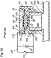
A sectional view of a schematic structure of this carbon monoxide
sensor is shown in Fig. 13. An electrolyte film 110 is composed of high
polymer having proton conductivity. On both surfaces of the film,
electrodes 112, 114 having a carbon cloth containing kneaded carbon
powder and a platinum catalyst carried thereon are bonded by hot press.
Mesh metal plates 116, 118 are disposed on the surface of the electrodes
112, 114, the surface on which the electrolyte film 110 is not disposed,
respectively. The electrolyte film 110, electrodes 112, 114, and metal
plates 116, 118 are held by flanges 120a, 122a provided inside of metal
cylindrical holders 120, 122. An O-ring 126 for sealing gas is disposed at
the electrolyte film 110 side at the end of the holder 122.
On the outer circumference of the holders 120, 122, threaded
portions 120b, 122b are formed. The holders 120, 122 are fixed by being
driven into threaded portions 124a, 124b formed inside of an insulating
member 124 made of polytetrafluoroethylene such as Teflon (a trademark
of Du Pont).
At one end of the holder 120, one end of a gas influent passage 128
is connected, from which object gas (fuel gas in this case) is introduced into
the carbon monoxide sensor. One end of the holder 122 is not connected
to the gas influent passage 128 and opens to an atmosphere.
Another end of the gas influent passage 128 is connected to a
branch port 140a provided at a part of a fuel gas passage 140 to be
introduced into the fuel cell.
Detecting terminals 120T, 122T are provided at the holders 120,
122, and an electric circuit 130 is connected to them. The electric circuit
130 is composed of a voltmeter 132, and a resistor 134, for adjusting the
load current, connected in parallel with the voltmeter. The detecting
terminal 120T and 122T are connected to the negative and positive
electrodes, respectively.
An operation of the carbon monoxide sensor will be explained. The
object gas (fuel gas) containing much hydrogen gas reaches the electrode
112 through the gas influent passage 128. The electrode 114 always
contacts with oxygen gas in the atmosphere. Therefore, on the surface of
the electrolyte film 110 contacting with the electrodes 112, 114, hydrogen
gas and oxygen gas react similarly to the fuel cell to generate an
electromotive force between the electrodes 112 and 114. A resistor 134
connected between the electrodes 112 and 114 makes a specified load
current flow, and the voltmeter 132 detects a voltage between the
electrodes 112 and 114.
In this situation, if carbon monoxide is mixed in the object gas, the
carbon monoxide is adsorbed to the platinum catalyst at the electrode 112
and has the electrode 112 poisoned. As a result, that prevents hydrogen
gas and oxygen gas from reacting and lowers the voltage between the
electrodes 112 and 114. Since the concentration of carbon monoxide
relates to a degree of poisoning, by measuring the voltage between the
electrodes 112 and 114, the concentration of carbon monoxide in the object
gas can be detected.
In this carbon monoxide sensor, to the extremely thin electrolyte
film 110 made of high polymer sealing the object gas and atmosphere, a
differential pressure of object gas and atmosphere (usually several
atmospheres) is always applied. In such circumstance, an abnormally
high pressure or an unexpected large pressure due to vibration or the like
is applied in concentration, especially in the circle in Fig. 13. The
pressure may breaks the electrolyte film 110, and the object gas with high
content of hydrogen gas may leak out to the atmosphere. To avoid such
breakage, a structure having a safety valve for releasing the object gas in
case of the abnormal pressure. In any case, the leak of the object gas into
the atmosphere cannot be avoided.
Japanese Patent Laid-open No.11-219716 discloses another carbon
monoxide sensor for detecting carbon monoxide in the fuel gas containing
much hydrogen gas supplied in the fuel cell.
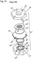
A perspective exploded view of a schematic structure of this carbon
monoxide sensor is shown in Fig. 14. An electrolyte film 50 is an electron
exchange film composed of high polymer having proton conductivity, for
example, NAFION (a trademark of Du Pont). On the both sides of the
film, an anode 42 and cathode 44 containing catalyst particles are
disposed. Conductive diffusion portions 43 and 45 made of carbon paper
contact with the anode 42 and cathode 44, respectively. The conductive
diffusion portion 43 contacts with a housing 54 having an object gas inlet
59, an anode flow channel 46 in which the object gas flows, and an object
gas outlet 51. The cathode 44 is exposed to the ambient air through an
opening 52 of the housing 54. A metal current collector plate 49 in which
a plurality of holes are formed contacts with the conductive diffusion
portion 45 and transfers the current to a terminal 47. The terminal 47
projects outward from the housing 54 through a slot 55.
An operation of the carbon monoxide sensor will be explained. The
object gas (fuel gas) having much hydrogen gas reaches the anode flow
channel 46 through the object gas inlet 59. From here, the gas passes
through the conductive diffusion portion 43 and is exhausted from the
outlet 51. The cathode 44 always contacts with oxygen gas in the
atmosphere. Therefore, on the surface of the electrolyte film 50
contacting with the anode 42 and cathode 44, hydrogen gas and oxygen
gas chemically react similarly to the fuel cell generating electricity with
using hydrogen gas and oxygen gas, and generates an electromotive force
between the anode 42 and cathode 44. The current and voltage at this
time are detected by a current detecting device and a voltage detecting
device (not shown) connected between the terminal 47 and housing 54.
In this situation, if carbon monoxide is mixed in the object gas, the
carbon monoxide is adsorbed on catalyst particles in the anode 42, and
hence poisons the anode 42. As a result, that prevents hydrogen gas and
oxygen gas from reacting, and lowers the electromotive force between the
anode 42 and cathode 44. Since the concentration of carbon monoxide
varies depending on a degree of poisoning, by measuring the current
change or voltage change due to drop of the electromotive force, the
concentration of carbon monoxide in the object gas can be detected.
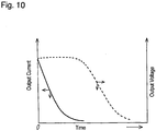
The resultant measurement of an output characteristic of the
carbon monoxide sensor is indicated with a broken line in Fig. 10. It
takes several minutes from introducing the object gas containing 50ppm of
carbon monoxide into the carbon monoxide sensor to chainging the sensor
output or electromotive force. In this period, the voltage or current from
the carbon monoxide sensor does not change, and therefore voltage change
or current change cannot be measured. Thus, the concentration of
carbon monoxide cannot be detected.
SUMMARY OF THE INVENTION
The invention presents a carbon monoxide sensor includes the
following portions:
In this carbon monoxide sensor, the object gas does not leak to the
atmosphere.
A carbon monoxide sensor having a short response time is also
presented which includes the following portions:
BRIEF DESCRIPTION OF THE DRAWINGS
Fig. 1A is a schematic front sectional view of a carbon monoxide
sensor according to exemplary embodiment 1 of the present invention;
Fig. 1B is a side sectional view of the carbon monoxide sensor
according to embodiment 1 of the invention;
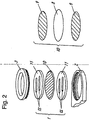
Fig. 2 is a perspective exploded view of a detector of the carbon
monoxide sensor according to embodiment 1 of the invention;
Fig. 3 is a sectional view of the detector of the carbon monoxide
sensor according to embodiment 1 of the invention;
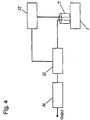
Fig. 4 is a block diagram of a detecting circuit of the carbon
monoxide sensor according to embodiment 1 of the invention;
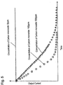
Fig. 5 is an output current characteristic diagram of the carbon
monoxide sensor according to embodiment 1 of the invention;
Fig. 6 is a perspective exploded view of a detector of a carbon
monoxide sensor according to exemplary embodiment 2 of the invention;
Fig. 7 is a block diagram of a detecting circuit of the carbon
monoxide sensor according to embodiment 2 of the invention;
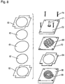
Fig. 8 is a perspective exploded view of a detector of a carbon
monoxide sensor according to exemplary embodiment 3 of the invention;
Fig. 9 is a block diagram of the carbon monoxide sensor according to
embodiment 3 of the invention;
Fig. 10 is an output characteristic diagram of the carbon monoxide
sensor according to embodiment 3 of the invention, and a carbon monoxide
sensor in a prior art;
Fig. 11 is a block diagram of a carbon monoxide sensor according to
exemplary embodiment 4 of the invention;
Fig. 12 is a perspective exploded view of a detecting element of the
carbon monoxide sensor according to embodiment 4 of the invention;
Fig. 13 is a schematic sectional view of a conventional carbon
monoxide sensor; and
Fig. 14 is a perspective exploded view of a schematic structure of
the conventional carbon monoxide sensor.
BEST MODE FOR CARRYING OUT THE INVENTION
Embodiments of the invention will be explained below by referring
to Fig. 1A to Fig. 12.
(Exemplary Embodiment 1)
Fig. 1A and Fig. 1B are schematic front sectional view and side
sectional view of a carbon monoxide sensor 1 according to exemplary
embodiment 1 of the present invention. Fig. 2 is a perspective exploded
view for explaining the structure of a detector thereof. Fig. 3 is a
sectional view explaining the flow of object gas near the detector disposed
in the pipe. Fig. 4 is a block diagram of a detecting circuit. Fig. 5 is an
output current characteristic diagram of the carbon monoxide sensor.
In Figs. 1A and 1B, a detector 1 detects the concentration of carbon
monoxide in object gas. The detector 1 is fixed with a holder 2 made of
insulating polytetrafluoroethylene, for example, Teflon (a trademark of Du
Pont), and a ring 3. A part of the holder 2 is inserted and fixed in a
mounting threaded portion 4 made of stainless steel (for example, SUS303
in the JIS standard). The mounting threaded portion 4 is driven and
fixed in an object gas pipe 22 of a fuel cell through an O-ring (not shown).
Fig. 1A and Fig. 1B show only the object gas pipe 22, which is cut off. The
detector 1 is fixed in parallel with the flow of the object gas. At both sides
of the detector 1, a Teflon-coated output lead wire 5 is connected to a
junction 6. The output lead wire 5 is connected to an output cable 7
leading to an external detecting circuit.
In Fig. 2, at both sides of a proton conductive electrolyte film 8
having a diameter of 1.4cm made of fluorine high polymer material, two
first electrodes 9 are disposed. In the film 8, a platinum catalyst and
carbon powder applied on a carbon cloth having a diameter of 1cm are
affixed with fluorine high polymer material. The electrolyte film 8 held
by the two first electrodes 9 is affixed by a hot press at a temperature of
130°C. In order to prevent the two first electrodes 9 from partial short-circuiting
due to slight position deviation during the hot press, the
diameter of the electrolyte film 8 is larger than the diameter of the first
electrodes 9.
At both sides of a detecting element 10 including the electrolyte film
8 and two first electrodes 9, two second electrodes 11 each having a disk
shape of a diameter of 1.3cm and a thickness of 1mm made of stainless
steel (for example, SUS303 of the JIS standard). The electrode 11 has
two slender penetration holes 15 are disposed. The surface of the second
electrodes 11 is smoothly processed to have an average roughness of 1.6µm
or less, and a gold plating layer having a thickness of 1µm is formed
thereon. The shape and size of the penetration holes 15 are not
particularly specified as far as the object gas can pass through.
The detector 1 including the detecting element 10 and two second
electrodes 11 is put in the holder 2, and is fixed by driving in the ring 3
from above the detector 1.
The configuration where the detector 1 is mounted on the object gas
pipe 22 is shown in Fig. 3. Fig. 3 is a view from direction A in Fig. 1A,
and shoes only the object gas pipe 22 cut off. The arrow in Fig. 3 shows
the flowing direction of the object gas. The detector 1 is held with the
holder 2 and ring 3 in parallel with the flow of the object gas, and thus, the
pressure of the object gas is applied almost equally to both sides of the
detector 1. Therefore, contrary to the prior art, the electrolyte film 8 in
the detector 1 is not exposed to a differential pressure of several
atmospheres of the object gas and the atmosphere structurally. Hence,
the electrolyte film 8 is hardly broken. Even if an unexpected large
stress breaks the electrolyte film 8 is broken, the object gas does not leak
to the atmosphere. As a result, no safety valve is needed, and gets the
structure very simple.
In Fig. 4, the detector 1 is connected to a direct-current power
source 12 and an ampere meter 13 as current detecting means through the
output cable 7. The ampere meter 13 is connected to a microcomputer 14
as a concentration calculating section for determining the concentration of
carbon monoxide in the object gas from a detected current. The
microcomputer 14 calculates a current difference (i.e., the current change
speed) at every specific time (for example, one second), and thus produces
a resultant concentration of carbon monoxide with referring to a
correlation table. The table, which is stored in a ROM, shows a
correlation between the current change speed and concentration of carbon
monoxide.
An operation of the carbon monoxide sensor of the embodiment will
be explained.
In this embodiment, oxygen gas cannot be introduced because the
entire detector 1 is disposed in the object gas. Therefore, the cell reaction
as in the prior art does not take place. In the embodiment, therefore, the
sensor detects the concentration of carbon monoxide according to the
following operation.
The object gas containing much hydrogen such as fuel gas supplied
in fuel cell reaches the detector 1 passes through the penetration holes 15
of the second electrodes 11, and reaches the detecting element 10. Since
first electrodes 9 included in the detecting element 10 are mostly made of
a carbon cloth, the object gas diffuses in the carbon cloth and reaches the
carbon powder carrying the platinum catalyst. The two first electrodes 9
are connected to the positive and negative terminals of the direct-current
power source 12, respectively. At the first terminals 9, the hydrogen in
the object gas reacts as shown in the following formulas:
Positive electrode: H2 → 2H++2e-
Negative electrode: 2H++2e- → H2
As shown in formula (1), the hydrogen is dissociated at the first
electrode 9 of the positive electrode side, and the produced proton (H+)
passes through the electrolyte film 8 and reaches the first electrode 9 of
the negative electrode side. As a result, as shown in formula (2), the
electron e is received again, and hydrogen is produced. Therefore, the
hydrogen forms a closed circuit between the detecting element 10 and
direct-current power source 12, and a current depending on the proton
conductivity flows along the circuit.
If carbon monoxide is contained in the object gas, the surface of the
platinum catalyst is poisoned as the carbon monoxide is adsorbed. That
prevents the circuit from reacting as shown in formulas (1) and (2) and
decreases the current. Therefore, monitoring this current provides an
output corresponding to the concentration of the carbon monoxide.
Fig. 5 shows an output current characteristic of the detecting
element 10 through which the object gas passes. In Fig. 5, the axis of
abscissas denotes time, and the axis of ordinates represents the output
current. A voltage of about 0.4V is applied to the detecting element 10.
When the concentration of carbon monoxide is 0ppm, the output current is
constant. When carbon monoxide is mixed in the object gas, the output
current decreases according to the time. As shown in Fig. 5, the
decreasing speed of the output current differs depending on the
concentration of carbon monoxide, that is, the higher is the concentration,
the faster is the decreasing speed of the output current. That is because
the platinum catalyst is poisoned in a shorter time as the concentration is
higher. The microcomputer 14 determines this changing speed of output
current by the changing amount of the output current in every specific
time (for example, one second), and detects the concentration of carbon
monoxide. It means that the response time of this sensor is one second.
For comparison, the response time is measured in a conventional
carbon monoxide sensor employing the cell reaction between hydrogen
and oxygen. The output potential changes in several minutes after
50ppm of carbon monoxide flows. This shows that the carbon monoxide
sensor according to the embodiment has much shorter response time than
the conventional sensor.
In the conventional sensor shown in Fig. 13, since the electrodes
112, 114 contacting with mesh metal plates 116, 118 with point contact or
line contact makes the output voltage unstable and makes noise notable.
In the sensor according to the embodiment, the second electrodes 11
having flat plates whose surfaces are smoothed and plated with gold
contact widely with the first electrodes 9. Therefore, an extremely stable
output current is obtained.
According to the embodiment, an ordinary ampere meter is used as
a current detecting unit. But, it is not limited to this, and then, may use
various current detecting devices such as a current transformer.
According to the embodiment, the applied voltage to the detecting
element 10 is about 0.4V based on the following reason.
In order to determine the voltage of the direct-current power source
12, a poisoning characteristic is measured while the object gas containing
carbon monoxide passes along with the various applied voltage. The
applied voltage exceeding 1V makes the output current very unstable.
This is considered because the platinum catalyst in the first electrodes 9 is
too highly activated with the high applied voltage, and the carbon
monoxide is adsorbed and simultaneously desorbed. The carbon
monoxide adsorbed on the platinum catalyst (poisoning) prevents the
catalyst from originally functioning and declines the output current. But
soon after that, the carbon monoxide is desorbed, the output current starts
increasing again. This process, which repeats randomly, makes the
output current extremely unstable.
To obtain a stable output current, the voltage should be lower than
1V. However, if being less than 0.1V, the voltage makes the output
current too small to be distinguished from noise. Therefore, in order to
obtain a favorable output current, an appropriate applied voltage ranges
0.1V to 1V. However, as the applied voltage is higher, the output current
increases, and the power consumption also increases, and hence the shape
and size of the electrodes must be designed appropriately.
From the comprehensive viewpoint of stability of the output current,
sensitivity, noise, and shape and size of electrodes, the applied voltage
preferably ranges 0.3V to 0.8V, and more preferably 0.4V to 0.5V.
(Exemplary Embodiment 2)
Fig. 6 is a perspective exploded view of a detector of a carbon
monoxide sensor according to embodiment 2 of the invention. Fig. 7 is a
block diagram of a detecting circuit.
In the embodiment, the same parts as in embodiment 1 are denoted
by the same reference numerals, and detailed description is omitted, and
only the difference will be explained.
The carbon monoxide sensor in embodiment 1 does not include a
unit for desorbing carbon monoxide from the platinum catalyst by force
after the platinum catalyst is poisoned. Although sufficiently functioning
as an alarm or switch for telling that the concentration of carbon
monoxide exceeds a certain level, this sensor does not sufficiently function
as a carbon monoxide sensor having a reversible function since the
reaction is irreversible. According to embodiment 2, as shown in Fig. 6, a
heater 16 for heating the poisoned platinum catalyst due to adsorption of
carbon monoxide to recover the function of the platinum catalyst is
disposed at one side of the detector 1. In the heater 16, a heating element
17 made of a nichrome wire formed in a specified shape as shown in Fig. 6
is held by a high polymer sheet 18 of Teflon or fluorine compound blanked
in the same shape as the element. Further, a heater cable 19 is
connected to the heating element 17 to supply current, and the heater 16
is formed in a flat plate by hot press. Object gas passes through slits 20
formed in the heater 16. As far as the object gas pass through,
penetration holes may be provided instead of the slits 20. The shape and
size of penetration holes or slits are not particularly specified.
The heater 16 is disposed between the detector 1 and holder 2 as
shown in Fig. 6. The heater 16 and detector 1 are held and fixed by
driving the ring 3 into the holder 2 from above. The detector 1 composed
in this way is inserted and fixed into the mounting threaded portion 4
similarly to Fig. 1A and Fig. 1B.
The detecting circuit shown in Fig. 7 is composed by adding a
heater control circuit 21 to the detecting circuit according to embodiment 1
shown in Fig. 4.
An operation of the carbon monoxide sensor according to
embodiment 2 will be explained. A basic operation is the same as in
embodiment 1, except that the heater 16 according to this embodiment.
That is, by heating the platinum catalyst by the heater 16 to desorbe the
carbon monoxide adsorbed on it, the carbon monoxide sensor functions
again.
When judging more concentration of the carbon monoxide than a
specified one is contained, the microcomputer 14 sends a judging signal to
the heater control circuit 21. Then, the heater control circuit 21 supplies
a current the heater for heat it to the temperature of about 130°C. As a
result, the detector 1 is heated, and thus the carbon monoxide adsorbed on
the platinum catalyst is desorbed. Therefore, even if the platinum
catalyst is poisoned, the carbon monoxide sensor functions repeatedly.
Such carbon monoxide sensor has the basically same output current
characteristic as that shown in Fig. 5. After the heater 16 operates to be
heated to 130°C after the poisoning, the heater 16 is turned off to cool
down, and the output current is measured again for the object gas
containing 0ppm concentration of carbon monoxide. As a result, the
original output current is nearly recovered. Thus, the carbon monoxide
sensor capable of recovering the detecting function reversibly even after
poisoned is obtained.
According to embodiments 1 and 2, the detector 1 is disposed
substantially in parallel with the flow of object gas, but may be disposed in
any direction as far as the pressure of the object gas can be applied almost
equally to both sides of the detector 1.
Specific materials mentioned in embodiments 1 and 2 are only
examples for composing the carbon monoxide sensor of the invention, and
are not limited only to them.
Thus, in spite of an extremely simple structure, a carbon monoxide
sensor does not permit the object gas to escape to the atmosphere.
Moreover, a carbon monoxide sensor is capable of recovering the
detecting function even if poisoned.
(Exemplary Embodiment 3)
Fig. 8 is a perspective exploded view of a carbon monoxide sensor
according to exemplary embodiment 3 of the present invention. Fig. 9 is
a block diagram of the sensor. Fig. 10 is an output characteristic diagram
of the sensor and a conventional sensor.
In Fig. 8, at both sides of a proton conductive electrolyte film 61
having a diameter of 1.4cm and made of fluorine high polymer material,
upper and lower electrodes 62 are disposed. In each electrode, an alloy
catalyst containing platinum and gold at a ratio of 3:1 and carbon powder
affixed on a carbon cloth having a diameter of 1cm with a fluorine high
polymer material. Outside of the two electrodes 62, seal members 63
made of silicon high polymer having a thickness of 0.25mm for preventing
gas from leaking are provided. The proton conductive electrolyte film 61
held by the two electrodes 62 and seal members 63 is affixed by a hot
pressing at a temperature of 130°C. Thus, a detecting element 64
includes the proton conductive electrolyte film 61, two electrodes 62, and
two seal members 63.
In Fig. 9, on one surface of the detecting element 64, a positive
electrode current collector plate 68 contacts with a gas passage 67 having
a gas inlet 65 and an gas outlet 66. The gas passage 67 is formed, by
cutting, on the surface of the positive electrode current collector plate 68
made of stainless steel (for example, SUS304 of the JIS standard) in width
and pitch of 0.5mm and depth of 0.3 mm within the area of the electrode
62. The dimensions of the gas passage 67 are not particularly specified
as far as a specified gas flow rate is assured (50cc/min. in embodiment 3).
The surface of the positive electrode current collector plate 68 is cut and
plated with a gold layer of a thickness of 1µm.
On another surface of the detecting element 64, a negative electrode
current collector plate 70 made of stainless steel (for example, SUS304 of
the JIS standard) in which multiple holes 69 having a diameter of 1.5mm
are formed is disposed. The surface of the negative electrode current
collector plate 70 is also plated with a gold layer having a thickness of
1µm.
At the side of the negative electrode current collector plate 70 not
contacting with the detecting element 64, i.e., above the negative electrode
current collector plate 70 in Fig. 9, a gas chamber 72 formed, by cutting,
with stainless steel (for example, SUS304 of the JIS standard) having a
gas outlet 71 is disposed. An orifice 73 having a diameter of 0.8mm is
connected to the gas outlet 71 as a flow rate suppressing unit.
The positive electrode current collector plate 68, detecting element
64, negative electrode current collector plate 70, and gas chamber 72 are
fixed in this order with four screws 74.
At the gas inlet 65 and outlet 66, a gas feed unit 75 and a gas
exhausting unit 76 made of pipes having tapered threads are connected,
respectively. At the leading end of the gas feed unit 75, a valve 77 and
switching valve 78 for switching the object gas and humidified air. The
humidified air to be supplied into the fuel cell is partly branched and fed
into the switching valve 78. The outlet sides of the gas exhausting unit
76 and orifice 73 are piped so as to be confluent, and the valve 77 is
provided at the leading end.
The positive electrode current collector plate 68 and negative
electrode current collector plate 70 are connected to positive and negative
terminals of a direct-current power source 79, respectively. In order to
detect the current flowing between the positive electrode current collector
plate 68 and negative electrode current collector plate 70, an ampere
meter 80 is connected as a current detecting unit in series of the direct-current
power source 79. In order to detect the voltage between the
positive electrode current collector plate 68 and negative electrode current
collector plate 70, similarly, a voltmeter 81 is connected as a voltage
detecting unit. Outputs of the ammeter 80 and voltmeter 81 are
connected to a microcomputer 82. The microcomputer 82 calculates the
change speed of the current, for example, at every one second from the
current detected by the ampere meter 80, and thus produces the resultant
concentration of carbon monoxide with referring to a correlation table.
The table, which is stored in a ROM, shows a correlation between the
current and a concentration of carbon monoxide. Further, the
microcomputer 82 controls to turn on and off the direct-current power
source 79, to operate the switching valve 78, and to open and close the
valve 77 in order to recover (or refresh) a function of the catalyst
adsorbing carbon monoxide.
An operation of the carbon monoxide sensor according to
embodiment 3 will be explained below.
In order to suppress output fluctuations due to a drying of the
proton conductive electrolyte film 61, the microcomputer 82 opens two
valves 77 and switches the switching valve 78 to the humidified air side to
pass humidified air for 30seconds. The flow rate of the humidified air is,
for example, 50cc/min. The duration of 30seconds is necessary for
replacing the gas in the sensor piping and gas passage 67 with the
humidified air at the flow rate of 50cc/min. Therefore, since the
replacement time differs with the flow rate and size of the gas passage 67,
the duration in embodiment 3 is not particularly specified.
Then, the microcomputer 82 switches the switching valve 78 to the
object gas side. The flow rate of the object gas is 50cc/min. The object
gas is led into the gas passage 67 through the valves 77, gas feed unit 75,
and gas inlet 65. Since the gas passage 67 contacts with the electrodes
62, the object gas diffuses uniformly into the carbon cloth composing the
electrodes 62 as the gas flows in the gas passage 67, and reaches the
catalyst composed of an alloy of platinum and gold. The object gas is
then exhausted through the outlet 66, gas exhausting unit 76, and valve
77.
In 30seconds after the above operation, after the gas in the piping
and gas passage 67 is replaced with the object gas, the microcomputer 82
turns on the direct-current power source 79. A voltage is applied between
the positive electrode current collector plate 68 and negative electrode
current collector plate 70. According to embodiment 3, the voltage is 0.1V.
By this operation, hydrogen in the object gas reacts on the catalyst of the
electrodes 62 as in the following formulas at the positive electrode and
negative electrode, respectively:
Positive electrode: H2 → 2H++2e
Negative electrode: 2H++2e- → H2
At the positive electrode 62, as shown in formula (3), the hydrogen
is dissociated, and the produced proton (H+) reaches the negative electrode
62 through the proton conductive electrolyte film 61. Then, as shown in
formula (4), the electron (e-) is received, and hydrogen is generated again.
Therefore, the hydrogen forms an electrically closed circuit between the
detecting element 64 and direct-current power source 79, and a current
depending on the proton conductivity flows.
If carbon monoxide is contained in the object gas, the surface of the
catalyst composed of an alloy of platinum and gold is poisoned as the
carbon monoxide is adsorbed. As a result, that prevents the reactions
shown in formulas (3) and (4), and decreases the current. The
microcomputer 82 calculates the decreasing speed of the current in every
second and produces the resultant concentration of carbon monoxide as an
output by referring to a correlation table showing a correlation between
the current decreasing speed and the concentration of carbon monoxide.
As this operation continues, the catalyst is poisoned by the carbon
monoxide, and the current flow decreases. The current changing speed
at this time is much slower than that at the start of using the sensor at the
same concentration of carbon monoxide, and thus a large detection error of
concentration occurs. The microcomputer 82 measures the current
decrease in the catalyst due to poisoning with carbon monoxide for a
specific time (1 minute in embodiment 3), and refreshes as follows.
First, the microcomputer 82 turns off the direct-current power
source 79, and switches the switching valve 78 to the humidified air side.
As a result, humidified air flows into the gas passage 67.
Hydrogen is being generated in the gas chamber 72 according to the
reaction shown in formula (3) and (4) until the switching valve 78 is
switched. Further, the orifice 73 connected to the outlet 71 of the gas
chamber 72 does not exhaust the generated hydrogen immediately, and a
specific volume of hydrogen remains in the gas chamber 72.
Therefore, the detecting element 64 forms a fuel cell composed of air
in the gas passage 67 and hydrogen in the gas chamber 72, and generates
an electromotive force. The electromotive force is generated with the
positive electrode current collector plate 68 as the positive electrode and
the negative electrode current collector plate 70 as the negative electrode.
The voltage of the electromotive force increases to a peak of about 0.8V
and then decreases gradually in embodiment 3. This is because the
hydrogen gas in the gas chamber 72 is gradually consumed for generating
the electromotive force.
During the above operation, oxygen in the humidified air is
supplied onto the poisoned catalyst, and reacts with carbon monoxide to
form carbon dioxide and to be separated from the catalyst.
Simultaneously, the electrode 62 at the poisoned catalyst side generates
an electromotive force of about 0.8V, which is more than 0.68V necessary
for desorbing the carbon monoxide adsorbing on the catalyst, and thus the
carbon monoxide is separated from the catalyst. Therefore, humidified
air fed into the gas passage 67 makes the oxidation and electromotive
force react on the poisoned catalyst, and refreshes the catalyst almost to
the original.
The voltage changes due to the electromotive force are monitored by
the voltmeter 81 connected between the positive electrode current
collector plate 68 and negative electrode current collector plate 70. The
microcomputer 82 determines a voltage changing speed from the output of
the voltmeter 81 and judges that the refreshing is over when the changing
speed turns negative (that is, the voltage decreases), and switches the
switching valve 78 to the object gas side.
Consequently, the microcomputer 82 waits until the humidified air
in the piping and gas passage 67 is replaced by the object gas (30seconds
in embodiment 3), turns on the direct-current power source 79, and
continues measuring a concentration of carbon monoxide.
By repeating this operation, the concentration of the carbon
monoxide is detected.
When stopping the operation of the carbon monoxide sensor, the
microcomputer 82 switches the switching valve 78 to the humidified air
side, and refreshes the catalyst as mentioned above. When the voltage
changing speed determined from the output of the voltmeter 81 turns
negative, the microcomputer 82 closes two valves 77, and turns off the
direct-current power source 79. As a result, the carbon monoxide sensor
stops, and the detecting element 64 is always exposed to humidified air, so
that output fluctuations due to drying of the proton conductive electrolyte
film 61 can be suppressed.
In Fig. 10, the solid line shows the output characteristic when the
object gas containing 20ppm of carbon monoxide flows in the carbon
monoxide sensor according to embodiment 3 at flow rate of 50cc/min. The
axis of abscissas shows time, and the axis of ordinates indicates an output
current. At time of 0, the direct-current power source 79 is turned on.
Simultaneously with turning-on of the direct-current power source 79, the
output current begins to decrease. By calculating this changing speed,
the microcomputer 82 detects the concentration of carbon monoxide. In
Fig. 10, the broken line denotes a characteristics of the prior art, in which
the output voltage does not change for several minutes for the same object
gas.
In this sensor, the object gas diffuses quickly in the electrodes 62
having the catalyst through the gas passage 67, and causes poisoning in
an early stage. A slow reaction of forming water from proton, electron
and oxygen does not substantially take place. Further, the catalyst made
of alloy of platinum and gold which is extremely poisoned quickly by
carbon monoxide. Hence, as compared with the prior art, the carbon
monoxide sensor of reacts extremely fast.
In embodiment 3, as the catalyst composing the electrodes 62, an
alloy of platinum and gold which is likely to be poisoned by carbon
monoxide is used. However, the catalyst used in the negative electrode
current collector plate 70 functioning as the negative electrode is not
necessary to consider the poisoning by carbon monoxide. Consequectly,
the negative electrode current collector plate 70 may be made of platinum
only, or an alloy of platinum and other noble metal, for example, platinum
and ruthenium, and thus the alloy material of platinum and gold is not
particularly specified.
(Exemplary Embodiment 4)
Fig. 11 is a block diagram of a carbon monoxide sensor according to
exemplary embodiment 4 of the present invention. Fig. 12 is a
perspective exploded view of a second detecting element of the carbon
monoxide sensor according to embodiment 4 of the invention.
In embodiment 4, the carbon monoxide sensor which is the same as
that in embodiment 3 (hereinafter carbon monoxide detector 83) is
combined with a hydrogen detector 84 which is the same sensor as in
embodiment 3 except that a catalyst of a positive electrode is made of an
alloy of platinum and ruthenium. The circuit of the hydrogen detector 84
is the same as that in the carbon monoxide detector 83 except that
voltmeter 81 is not connected.
The same parts as in embodiment 3 are denoted by the same
reference numerals, and the detailed description is omitted. Names of
the parts used in the carbon monoxide detector 83 are preceded by a word
"first", and those of the parts used in the hydrogen detector 84 are
distinguished by a preceding word "second" and subscript "a" attached to
the reference numerals.
In Fig. 12, a catalyst electrode 85 includes carbon powder carrying a
catalyst made of alloy of platinum and ruthenium which is affixed on a
carbon cloth having a diameter of 1cm with fluorine high polymer
material. Other parts including the proton conductive electrolyte film 61,
electrode 62, and seal member 63 are the same as those explained in Fig.
8.
During a measurement with the carbon monoxide sensor explained
in embodiment 3, if a concentration of hydrogen in the object gas changes
largely, the amount of proton flowing in the proton conductive electrolyte
film 61 varies, and the output current also changes. It may be therefore
hard to determine whether the output current changes according to a
change of a concentration of carbon monoxide or hydrogen. Consequently,
the carbon monoxide sensor explained in embodiment 3 operates
sufficiently to detect the concentration of carbon monoxide under a limited
condition, i.e., as far as the operation of the reformer is stable, and the
concentration of hydrogen from the reformer is almost constant.
However, the sensor may not exhibit sufficient performance, for example,
right after the reformer starts operating or when the concentration of
hydrogen fluctuates.
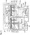
According to embodiment 4, as shown in Fig. 11, the hydrogen
detector 84 for detecting only the concentration of hydrogen is connected
to a first gas exhausting unit 76 of the carbon monoxide detector 83. The
concentration of carbon monoxide is compensated according to a change of
the concentration of hydrogen and issued.
A basic operation of the carbon monoxide sensor according to
embodiment 4 will be explained. The microcomputer 82 opens two valves
77, 77a, switches the switching valve 78 to a humidified air, and waits for
60seconds. The flow rate of the humidified air is set to 50cc/min.
Then, the microcomputer 82 switches the switching valve 78 to
object gas. The flow rate of object gas is set to 50cc/min. The object gas
flows through the first valve 77, first gas feed unit 75 and first inlet 65 of
the carbon monoxide detector 83, and is guided into the first gas passage
67 to contact with the catalyst made of alloy of platinum and gold in the
electrode 62. Then, the object gas passes through the first outlet 66 and
first gas exhausting unit 76. The gas further passes through the second
gas feed unit 75a and second inlet 65a of the hydrogen detector 84, and is
guided into the second gas passage 67a to reach the catalyst electrode 85
made of alloy of platinum and ruthenium in the second detecting element
86. The object gas is exhausted through the second outlet 66a, second
gas exhausting unit 76a, and second valve 77a.
In 60seconds after the switching valve 78 is switched to the object
gas, the gas in the piping and the first gas passage 67 and second gas
passage 67a is replaced by object gas. Then, the microcomputer 82 turns
on the first direct-current power source 79 and second direct-current
power source 79a of the carbon monoxide detector 83 and hydrogen
detector 84 at the same time. They apply voltages between the first
positive electrode current collector plate 68 and first negative electrode
current collector plate 70, and between the second positive electrode
current collector plate 68a and second negative electrode current collector
plate 70a. In embodiment 4, the voltage of each detector is set to 0.1V.
In each detector, the hydrogen in the object gas reacts at the catalysts of
the electrode 62 and catalyst electrode 85 in the positive and negative
electrodes as shown in the following formulas, and a current depending on
the proton conductivity flows in each detector.
Positive electrode: H2 → 2H++2e-
Negative electrode: 2H++2e- → H2
Under this condition, the carbon monoxide in the object gas is
adsorbed on the surface of the catalyst made of alloy of platinum and gold
in the first detecting element 64 of the carbon monoxide detector 83, and
poisons the catalyst. Then, the carbon monoxide prevents the carbon
monoxide detector 83 from reacting as shown in formulas (5) and (6), and
decreases a current. Since the carbon monoxide adsorbed on the catalyst
of the carbon monoxide detector 83, the object gas almost not containing
carbon monoxide flows into the hydrogen detector 84. The second
detecting element 86 having the catalyst electrode 85 made of an alloy of
platinum and ruthenium which is hardly poisoned by carbon monoxide
outputs the current depending on the concentration of hydrogen without
an affect of the carbon monoxide.
The microcomputer 82 calculates a decreasing speed of the current
of the carbon monoxide detector 83 in every second, and issues the
concentration of carbon monoxide by referring to a correlation table of
concentration of carbon monoxide determined from the current changing
speed and the output current of the hydrogen detector 84.
After the sensor continues to output a concentration of carbon
monoxide for a specific time (60seconds in embodiment 4), the
microcomputer 82 refreshes the sensor in the same manner as in
embodiment 3.
Upon waiting for the object gas to replace the humidified air in the
piping and the first gas passage 67 and second gas passage 67a (60seconds
in embodiment 4), the microcomputer 82 turns on the first direct-current
power source 79 and second direct-current power source 79a at the same
time, and continues to measure a concentration of carbon monoxide for a
specific time (60seconds in embodiment 4).
By repeating the above operation, the sensor detects a
concentration of carbon monoxide.
When stopping the operation of the carbon monoxide sensor,
similarly to embodiment 3, the microcomputer 82 switches the switching
valve 78 to the humidified air, and refreshes the sensor as mentioned in
above. When the voltage changing speed determined from the output of
the voltmeter 81 turns negative, the microcomputer 82 closes two valves
77, 77a, and turns off the first direct-current power source 79 and second
direct-current power source 79a, and then, stops the carbon monoxide
sensor. The first detecting element 64 and second detecting element 86
are always exposed to humidified air, so that output fluctuations due to a
drying of the first proton conductive electrolyte film 61 and second proton
conductive electrolyte film 61a can be suppressed.
In the carbon monoxide sensor according to
embodiment 4, from the
measurement of the output for the object gas containing 20ppm of carbon
monoxide flowing at flow rate of 50cc/min, it has been confirmed that the
same high response performance as in
embodiment 3 is obtained. This
depends on the following reasons:
Moreover, even if the concentration of hydrogen in the object gas varied is
measured, the sensor detects the concentration of carbon monoxide
accurately.
The material used in embodiments 3 and 4 is just an example for
providing the carbon monoxide sensor of the invention, and is not
particularly specified.
Thus, a carbon monoxide sensor having an extremely fast response
is obtained. Even if the hydrogen concentration in the object gas varies,
the carbon monoxide sensor is capable of detecting the carbon monoxide
concentration accurately.
INDUSTRIAL APPLICABILITY
The invention presents a carbon monoxide sensor not allowing the
object gas to leak into the atmosphere in spite of a very simple structure.
The invention presents a carbon monoxide sensor having an
excellent response performance capable of detecting concentration
utilizing a proton conductivity without inducing chemical reaction of slow
rate generating water and electricity from proton, electron and oxygen.