EP1155612A1 - Coated fishing components - Google Patents
Coated fishing components Download PDFInfo
- Publication number
- EP1155612A1 EP1155612A1 EP01303995A EP01303995A EP1155612A1 EP 1155612 A1 EP1155612 A1 EP 1155612A1 EP 01303995 A EP01303995 A EP 01303995A EP 01303995 A EP01303995 A EP 01303995A EP 1155612 A1 EP1155612 A1 EP 1155612A1
- Authority
- EP
- European Patent Office
- Prior art keywords
- paint
- conduit
- component
- coated
- coated fishing
- Prior art date
- Legal status (The legal status is an assumption and is not a legal conclusion. Google has not performed a legal analysis and makes no representation as to the accuracy of the status listed.)
- Granted
Links
- 239000003973 paint Substances 0.000 claims abstract description 61
- 238000004070 electrodeposition Methods 0.000 claims abstract description 24
- 229910000861 Mg alloy Inorganic materials 0.000 claims abstract description 15
- 239000010407 anodic oxide Substances 0.000 claims description 7
- 229910000838 Al alloy Inorganic materials 0.000 claims description 6
- 230000002787 reinforcement Effects 0.000 claims description 6
- 229910001069 Ti alloy Inorganic materials 0.000 claims description 4
- 238000000576 coating method Methods 0.000 claims description 4
- 238000005520 cutting process Methods 0.000 claims description 4
- 229910045601 alloy Inorganic materials 0.000 claims description 2
- 239000000956 alloy Substances 0.000 claims description 2
- 230000007246 mechanism Effects 0.000 description 12
- 230000009977 dual effect Effects 0.000 description 7
- 238000009987 spinning Methods 0.000 description 6
- 238000004804 winding Methods 0.000 description 6
- 230000005540 biological transmission Effects 0.000 description 4
- MUBZPKHOEPUJKR-UHFFFAOYSA-N Oxalic acid Chemical compound OC(=O)C(O)=O MUBZPKHOEPUJKR-UHFFFAOYSA-N 0.000 description 3
- 239000011248 coating agent Substances 0.000 description 3
- 229910052751 metal Inorganic materials 0.000 description 3
- 239000002184 metal Substances 0.000 description 3
- 230000010355 oscillation Effects 0.000 description 3
- 230000002093 peripheral effect Effects 0.000 description 3
- XLYOFNOQVPJJNP-UHFFFAOYSA-N water Substances O XLYOFNOQVPJJNP-UHFFFAOYSA-N 0.000 description 3
- QAOWNCQODCNURD-UHFFFAOYSA-N Sulfuric acid Chemical compound OS(O)(=O)=O QAOWNCQODCNURD-UHFFFAOYSA-N 0.000 description 2
- 238000005260 corrosion Methods 0.000 description 2
- 230000007797 corrosion Effects 0.000 description 2
- 238000000151 deposition Methods 0.000 description 2
- 230000008021 deposition Effects 0.000 description 2
- 230000000694 effects Effects 0.000 description 2
- 230000000149 penetrating effect Effects 0.000 description 2
- 229920003002 synthetic resin Polymers 0.000 description 2
- 239000000057 synthetic resin Substances 0.000 description 2
- 238000004078 waterproofing Methods 0.000 description 2
- QVGXLLKOCUKJST-UHFFFAOYSA-N atomic oxygen Chemical compound [O] QVGXLLKOCUKJST-UHFFFAOYSA-N 0.000 description 1
- 238000005452 bending Methods 0.000 description 1
- 238000005266 casting Methods 0.000 description 1
- 125000002091 cationic group Chemical group 0.000 description 1
- KRVSOGSZCMJSLX-UHFFFAOYSA-L chromic acid Substances O[Cr](O)(=O)=O KRVSOGSZCMJSLX-UHFFFAOYSA-L 0.000 description 1
- 238000010276 construction Methods 0.000 description 1
- 238000010586 diagram Methods 0.000 description 1
- AWJWCTOOIBYHON-UHFFFAOYSA-N furo[3,4-b]pyrazine-5,7-dione Chemical compound C1=CN=C2C(=O)OC(=O)C2=N1 AWJWCTOOIBYHON-UHFFFAOYSA-N 0.000 description 1
- 238000007654 immersion Methods 0.000 description 1
- 238000007373 indentation Methods 0.000 description 1
- 230000004048 modification Effects 0.000 description 1
- 238000012986 modification Methods 0.000 description 1
- 235000006408 oxalic acid Nutrition 0.000 description 1
- 230000003647 oxidation Effects 0.000 description 1
- 238000007254 oxidation reaction Methods 0.000 description 1
- 229910052760 oxygen Inorganic materials 0.000 description 1
- 239000001301 oxygen Substances 0.000 description 1
- 229920000768 polyamine Polymers 0.000 description 1
- 238000012958 reprocessing Methods 0.000 description 1
- 229920005989 resin Polymers 0.000 description 1
- 239000011347 resin Substances 0.000 description 1
- 238000002791 soaking Methods 0.000 description 1
- 238000005507 spraying Methods 0.000 description 1
Images





Classifications
-
- A—HUMAN NECESSITIES
- A01—AGRICULTURE; FORESTRY; ANIMAL HUSBANDRY; HUNTING; TRAPPING; FISHING
- A01K—ANIMAL HUSBANDRY; AVICULTURE; APICULTURE; PISCICULTURE; FISHING; REARING OR BREEDING ANIMALS, NOT OTHERWISE PROVIDED FOR; NEW BREEDS OF ANIMALS
- A01K89/00—Reels
-
- A—HUMAN NECESSITIES
- A01—AGRICULTURE; FORESTRY; ANIMAL HUSBANDRY; HUNTING; TRAPPING; FISHING
- A01K—ANIMAL HUSBANDRY; AVICULTURE; APICULTURE; PISCICULTURE; FISHING; REARING OR BREEDING ANIMALS, NOT OTHERWISE PROVIDED FOR; NEW BREEDS OF ANIMALS
- A01K89/00—Reels
- A01K89/01—Reels with pick-up, i.e. with the guiding member rotating and the spool not rotating during normal retrieval of the line
-
- A—HUMAN NECESSITIES
- A01—AGRICULTURE; FORESTRY; ANIMAL HUSBANDRY; HUNTING; TRAPPING; FISHING
- A01K—ANIMAL HUSBANDRY; AVICULTURE; APICULTURE; PISCICULTURE; FISHING; REARING OR BREEDING ANIMALS, NOT OTHERWISE PROVIDED FOR; NEW BREEDS OF ANIMALS
- A01K89/00—Reels
- A01K89/015—Reels with a rotary drum, i.e. with a rotating spool
- A01K89/0192—Frame details
-
- A—HUMAN NECESSITIES
- A01—AGRICULTURE; FORESTRY; ANIMAL HUSBANDRY; HUNTING; TRAPPING; FISHING
- A01K—ANIMAL HUSBANDRY; AVICULTURE; APICULTURE; PISCICULTURE; FISHING; REARING OR BREEDING ANIMALS, NOT OTHERWISE PROVIDED FOR; NEW BREEDS OF ANIMALS
- A01K89/00—Reels
- A01K89/01—Reels with pick-up, i.e. with the guiding member rotating and the spool not rotating during normal retrieval of the line
- A01K89/01121—Frame details
-
- Y—GENERAL TAGGING OF NEW TECHNOLOGICAL DEVELOPMENTS; GENERAL TAGGING OF CROSS-SECTIONAL TECHNOLOGIES SPANNING OVER SEVERAL SECTIONS OF THE IPC; TECHNICAL SUBJECTS COVERED BY FORMER USPC CROSS-REFERENCE ART COLLECTIONS [XRACs] AND DIGESTS
- Y10—TECHNICAL SUBJECTS COVERED BY FORMER USPC
- Y10S—TECHNICAL SUBJECTS COVERED BY FORMER USPC CROSS-REFERENCE ART COLLECTIONS [XRACs] AND DIGESTS
- Y10S411/00—Expanded, threaded, driven, headed, tool-deformed, or locked-threaded fastener
- Y10S411/90—Fastener or fastener element composed of plural different materials
- Y10S411/901—Core and exterior of different materials
- Y10S411/902—Metal core
- Y10S411/903—Resinous exterior
Definitions
- the present invention relates to coated components, and more particularly, to paint-coated fishing components utilized in fishing reels.
- the main types of fishing reels that are mounted on a fishing rod and used for reeling out and winding in fishing line are spinning reels, dual-bearing reels, and single-bearing reels. These types of fishing reels are provided with a reel body that attaches to a fishing rod, and a spool attached to the reel body for winding fishing line.
- the main parts of the reel bodys in dual-bearing reels are a frame, and side covers fastened with screws to both sides of the frame. In these side covers, protrusions, such as bosses for holding screws, are formed protruding on the reverse side of the side covers, in order to prevent the screw terminals from being exposed on the surface of the side covers.
- the protrusions have recesses, such as threaded sockets, whose tip ends are open, forming a so-called cap-screw configuration (in which the sockets are not bores completely penetrating the protrusions to otherwise open their base ends onto the obverse side of the side covers).
- the main components of such a fishing reel are made of an aluminum alloy or a magnesium alloy, for example, in order to make the fishing reel lighter.
- the main components are made of a magnesium alloy, their surface is coated with paint to increase their corrosion resistance.
- Coating with paint is carried out by spray coating or electrodeposition, for example.
- an anodic oxide film layer is usually formed on the main components, and then the main components are immersed in a paint bath to adhere the paint.
- the entire side cover is immersed in the paint bath, so that the paint adheres not only to the obverse side of the side cover, but also to the reverse side where the protrusion portions are formed.
- the protrusions of a cap screw construction there is the risk that paint invading the protrusion openings builds up in the threaded sockets. Paint building up in the threaded sockets brings about the need to reprocess the screw hole, as it may become impossible to insert the screw all the way to the end.
- An object of the present invention is, for coated fishing components formed with recesses, to make build-up of coating paint in the recesses unlikely.
- a painted fishing gear component used for a fishing reel includes a main component and a paint film layer formed by soaking the main component with paint.
- the main component includes a main part, a recess portion provided with an opening formed on the main part, and a conduit formed on the main part, communicating the recess portion with its exterior.
- the main component is coated by immersion in paint after the main part has been provided with a recess portion and a conduit.
- the main part is provided with a conduit communicating the recess portion with its exterior. Consequently, excess paint is discharged through the conduit to the outside, so that paint is unlikely to build up in the recess portion.
- the main part is provided with a protrusion portion provided with said conduit and said recess portion with said opening at the protrusion portion's end.
- the main part is provided with a protrusion portion having a recess portion for attaching a screw or positioning, for example.
- the protrusion portion is provided with the conduit for communicating the recess portion with the exterior thereof, so that as in the first aspect of the present invention, paint is unlikely to build up in the recess portion.
- the paint film layer is an electrodeposition layer formed by electrodeposition. This improves the deposition of paint on the main component.
- a painted fishing gear component as in the third aspect further includes an anodic oxide film layer between the main component and the electrodeposition layer. This improves the corrosion resistance of the main part, as well as the deposition of the electrodeposition layer.
- the conduit is a slit formed in the protrusion portion.
- a slit can be arranged in the protrusion direction of the protrusion portion (that is, vertically) or perpendicular to the protrusion direction (that is, horizontally).
- the conduit is formed on a base side of the protrusion portion.
- the paint can be discharged easily, because the conduit is formed near the bottom of the recess portion.
- the conduit is formed extending from the opening to a base side of the protrusion portion. In that case, it is easy to form the conduit, for example by forming a vertical slot extending from the opening.
- the conduit is formed by cutting. In that case, it is easy to form the conduit, for example with a cutting tool, such as a T-slot cutter.
- the main component is made of an alloy selected from the group consisting of magnesium alloy, aluminum alloy and titanium alloy.
- a light metal such as magnesium alloy, aluminum alloy and titanium alloy, it is possible to make a light-weight main component.
- the main component is a side cover attached to a frame of a fishing reel.
- paint is unlikely to build up in the recess portions of the protrusion portions for attaching a screw or for positioning, formed protruding from a protrusion portion side (rear side) of the side cover.
- the conduit is formed in the protrusion portion, the protrusion portion side is not communicated with the exterior on the opposite side (obverse side) by otherwise penetrating the main part through the recess portion in the protrusion portion.
- water is prevented from entering from the obverse side to the reverse side through the conduit in the side cover when the side cover is attached to the frame.
- the side cover is screwed to the frame
- the protrusion portion is a boss portion for attaching a screw
- the recess portion is provided with a female thread into which said screw is screwed.
- the recess portion is a screw hole into which the screw for fastening the cover is screwed, and the conduit averts build-up of paint in the screw hole, so that reprocessing the screw hole becomes unnecessary.
- a painted fishing gear component as in any of the first to eleventh aspect further includes a reinforcement member mounted on the protrusion portion. In that case, it is possible to keep up the strength of the protrusion portion, even when the protrusion portion has been provided with a vertical slot extending from the opening serving as the conduit.
- a painted fishing gear component as in any of the first to twelfth aspect further includes a cover member that is a shutoff between the conduit its exterior.
- the cover member is furnished to function for example as the reinforcement member of the eleventh aspect of the present invention. That is, insofar as attaching another component to the main part is concerned, the cover member fulfills an equivalent role to that of the reinforcement member that attaches another member to the protrusion portion on the main part.
- the cover member is made of a metal, such as an aluminum alloy or a magnesium alloy, or of a synthetic resin, and can be fastened with screws to the main component at several locations.
- the conduit is blocked from the outside. Consequently, paint is unlikely to build up in the recess portion, and in particular in recess portions for accepting screws or the like, it can be prevented that water enters the gap between recess portion and screw. Furthermore, if the conduit is closed together with the opening of the recess portion, the waterproofing effect is increased even further. Also, arranging the cover member such that it is not exposed to the surface side makes it possible to improve the looks of the fishing gear component.
- the conduit opens to the same side as the opening.
- the opening of the conduit is arranged on the same side as the opening of the recess portion, so that the recess portion and the conduit can be machined easily. If additionally a cover member is provided, then these apertures can be shut easily, because it is sufficient to provide the cover member only on the side of the apertures.
- the conduit is formed such that the recess portion does not completely penetrate the main part. In that case, the recess portion and the conduit do not form through-holes. Therefore, if the main component is exposed to the surface side, the looks of the fishing gear component can be improved, and the waterproofing effect can be increased, because no water enters through the apertures on the other end of such through-holes.
- the main component is a reel body of a fishing reel.
- paint is unlikely to build up in the recess portions for attaching a screw or for positioning, formed in the reel body (main component).
- the reel body is provided with a boss portion to which another component can be screwed.
- paint is unlikely to build up in the boss portions which are protrusions portions to which another component, such as a lid member or a cover member, can be screwed to the reel body.
- the dual-bearing reel in accordance with the first embodiment of the present invention is a low profile reel for bait-casting.
- This dual-bearing reel includes a reel body 1, a handle assembly 2 for turning a spool, and a spool 4 for winding fishing line.
- the handle assembly 2 is disposed on one side of the reel body 1.
- the spool 4 is provided rotatably and detachably inside the reel body 1.
- a star drag 3 for adjusting drag is disposed on the same side of the reel body 1 as the handle 2.
- the reel body 1 includes a frame 5, and a first side cover 6a and a second side cover 6b attached to the two sides of the frame 5.
- the frame 5 includes a first side plate 7a and a second side plate 7b to which the first side cover 6a and the second side cover 6b are attached, and a plurality of connecting portions 8 connecting the first side plate 7a with the second side plate 7b into one unit.
- the first side cover 6a and the second side cover 6b are fastened with screws 30 from the inside of the first side plate 7a and the second side plate 7b to a plurality of protrusion portions 20 protruding on the rear side of the first side cover 6a and the second side cover 6b. Therefore, the screw terminals are not exposed to the surface side of the first side cover 6a and the second side cover 6b.
- the protrusion portion 20 includes a recess portion 22 in which female threads are formed and having an opening 21 at its tip end, and a conduit 25 formed base-endward communicating the recess portion 22 with its exterior.
- the conduit 25 is a slit arranged in a direction perpendicular to the direction in which the protrusion portion 20 protrudes (that is, horizontally), and is machined, for example with a with a T-slot cutter, so as to be communicated with the recess portion 22.
- the members constituting the reel body 1 are made of a magnesium alloy. A coating is applied to the surface of the main components 10.
- an anodic oxide film layer 11 is formed by anodic oxidation on the surface of the main components 10 made of magnesium alloy.
- An electrodeposition film layer 12 is formed by electrodeposition on the surface of the anodic oxide film layer 11.
- the anodic oxide film layer 11 is electrolytically decomposed in a solution of sulfuric acid, oxalic acid or chromic acid, and a film is formed due to oxygen generated at the anode.
- the electrodeposition film layer 12 is formed by electrodeposition using a cationic electrodeposition paint, whose main component is a polyamine resin.
- a cationic electrodeposition paint whose main component is a polyamine resin.
- the main components 10 which have been coated with the anodic oxide film layer 11 are immersed in a bath of the electrodeposition paint, and taking the main components 10 as the cathode and electrodes arranged in the bath of the electrodeposition paint as the anode, the main components 10 are electrolytically coated with the paint by applying a dc voltage.
- the main components 10 by electrodeposition, it is necessary to machine the main components 10 in a cutting process first.
- the first side cover 6a and the second side cover 6b which are two of the main components 10, are painted after forming the recess portion 22 (hole and female thread) and the conduit 25 in the protrusion portion 20.
- the protrusion portions 20 are provided with the conduits 25 communicated with the recess portions 22, so that when they are painted by electrodeposition, excess paint is discharged through the conduits 25 to the outside, preventing a build-up of paint in the recess portions 22.
- a spinning reel in accordance with the second embodiment of the present invention includes a handle 101, a reel body 102 rotatively supporting the handle 1, a rotor 103, and a spool 104.
- the rotor 103 is rotatively supported at the front of the reel body 102.
- the fishing line is wound around the outer peripheral surface of the spool 104, which is disposed at the front of the rotor 103 and can be shifted back and forth.
- the reel body 102 includes a reel body 102a provided with a space inside, a lid member 102b and a cover member 102c mounted detachably to the reel body 102a to shut the space in the reel body 102a, and a bearing member 102d (see Fig. 10) for mounting a rotation transmission mechanism 114 described below.
- the reel body 102a is made, for example, of a magnesium alloy, and is formed unitarily with a T-shaped rod attachment leg 102e extending horizontally at the top of the reel body 102a. As shown in Fig. 7, the space in the reel body 102a accommodates a rotor driving mechanism 105 for transmitting the rotation of the handle 101 to rotate the rotor 103, and an oscillation mechanism 106 for winding up the fishing line uniformly by shifting the spool 104 back and forth.
- the lid member 102b is made, for example, of a magnesium alloy, and screwed at three locations to the left side of the reel body 102a at a second screw portion 122, a third screw portion 123, and a fourth screw portion 124, as shown in Figs. 6 and 7.
- the cover member 102c which is for example made of a magnesium alloy, covers the rear end portion of the reel body 102a and is fastened at a first screw portion 121 to the reel body 102a at the upper rear.
- the rotor driving mechanism 105 includes a handle shaft 110, a face gear 111 and a pinion gear 112.
- the face gear 111 rotates together with the handle shaft 110, on which the handle 101 is mounted non-rotatively.
- the pinion gear 112 meshes with the face gear 111.
- the pinion gear 112 is tubular. Its front portion 112a penetrates the center of the rotor 103, and is fixed with a nut to the rotor 103.
- the middle and the rear end (with respect to the axial direction) of the pinion gear 112 are rotatively supported by bearings in the reel body 102.
- the oscillation mechanism 106 shifts the spool 104 back and forth, shifting back and forth the spool shaft 115 to which the center of the spool 104 is coupled via a drag mechanism 160.
- the rotor 103 includes a rotor unit 116, a bail arm 117, and a bail flipping mechanism 118.
- the bail arm 117 is disposed to the front of the rotor unit 116 and is pivotable between a line-releasing position and a line-winding position.
- the bail flipping mechanism 118 is mounted to the rotor unit 116 and is for returning the bail arm 117 into the line-winding position.
- the rotor unit 116 includes a cylindrical portion 130, a first rotor arm 131 and a second rotor arm 132.
- the cylindrical portion 130 is attached to the reel body 102a and can rotate freely around the spool shaft 115.
- the first rotor arm 131 and the second rotor arm 132 are arranged in opposition to one another on the sides of the cylindrical portion 130.
- the cylindrical portion 130, the first rotor arm 131 and the second rotor arm 132 can be made, for example, of an magnesium alloy, and are formed in one piece.
- the first and second rotor arms 131 and 132 respectively include first and second connection portions 131a and 132a arranged at a peripheral surface at the rear of the cylindrical portion 130, first and second arm portions 131b and 132b curving out and extending frontward from the first and second connection portions 131a and 132a, and first and second cover members 131c and 132c covering the outer portions of both the two connection portions 131a and 132a and the two arm portions 131b and 132b.
- the first and second connection portions 131a and 132a are formed in smooth circumferential continuation of the cylindrical portion 130.
- First and second bail support members 140 and 142 are mounted pivotably to the outer side at the tip of the first and second arm portions 131b and 132b.
- a line roller 141 for guiding fishing line to the spool 104, and a fixed shaft cover 147 are fixed to the front of the first bail support member 140, with the line roller 141 being arranged between the first bail support member 140 and the fixed shaft cover 147.
- the line roller 141 is mounted rotatively to the front end of the first bail support member 140.
- the fixed shaft cover 147 is shaped like a deformed cone with a sharply tapering tip.
- a bail 143 made by bending a wire into U-shape, is fixed between the tip of the fixed shaft cover 147 and the second bail support member 142.
- the first and second bail support members 140 and 142, the line roller 141, the bail 143, and the fixed shaft cover 147 constitute the bail arm 117, which guides the fishing line to the spool 104.
- the first screw portion 121 includes a first recess portion 121b and a first conduit 121c communicating the first recess portion with its exterior.
- the first recess portion 121b has a first opening 121a and is formed at an upper rear portion of the reel body 102a.
- the inner wall of the first recess portion 121b is provided with a female thread, and the cover member 102c is fastened to the reel body 102a by screwing a screw 180 into the first recess portion 121b.
- the reel body 102a and the cover member 102c are provided with indentations, which accommodate the head of the screw 180 so that it does not stick out from the outer peripheral surface of the cover member 102c.
- the cover member 102c is a shutoff between the first conduit 121c its exterior.
- the first conduit 121c is provided with an aperture on the same side as the first opening 121a. Furthermore, the first conduit 121c is formed such that the first recess portion 121b does not bore through the reel body 102a.
- the second screw portion 122 includes a second recess portion 122b and a second conduit 122c communicating the second recess portion 122b with its exterior (that is, with the inside of the reel body 102).
- the second recess portion 122b has a second opening 122a and is formed on the upper left side of the reel body 102a.
- the inner wall of the second recess portion 122b is provided with a female thread, and the lid member 102b is fastened to the reel body 102a by screwing a screw 180 into the second recess portion 122b.
- the second conduit 122c is formed base-endward of the second recess portion 122b.
- the third screw portion 123 includes a third recess portion 123b and a third conduit 123c communicating the third recess portion 123b with its exterior (that is, an aperture to the side of the bearing member 102d on which the rotation transmission mechanism 114 is mounted).
- the third recess portion 123b has a third opening 123a and is formed on the lower left side of the reel body 102a.
- the rotation transmission mechanism 14 includes a pinion gear 112 mounted on the spool shaft 115, a linking shaft 114a, a bearing member 102d which rotatably supports the lower end of the linking shaft 114a, a bearing member which rotatably supports the upper end of the linking shaft 114a, and first to third gears 114b to 114d.
- the inner wall of the third recess portion 123b is provided with a female thread, and the lid member 102b is fastened to the reel body 102a by screwing a screw 180 into the third recess portion 123b.
- the third conduit 123c is communicated with the exterior thereof through the lower end of the third recess portion 123b.
- All components of the reel body 102a are made of a magnesium alloy, and as in the first embodiment, they are painted by electrodeposition after the screw holes have been formed.
- the details of the electrodeposition are the same as in the first embodiment, so that their further explanation has been omitted.
- the reel body 102a is provided with first to third conduits 121c to 123c communicating with the first to third recess portions 121b to 123b, so that when it is painted by electrodeposition, excess paint is discharged from the first to third conduits 121d to 123d to the outside, preventing a build-up of paint in the first to third recess portions 121c to 123c.
- the main part is provided with a conduit communicating the recess portion with its exterior, so that excess paint is discharged from the conduit to the outside, preventing a build-up of paint in the recess portion.
Landscapes
- Life Sciences & Earth Sciences (AREA)
- Environmental Sciences (AREA)
- Animal Husbandry (AREA)
- Biodiversity & Conservation Biology (AREA)
- Developing Agents For Electrophotography (AREA)
- Paints Or Removers (AREA)
- Glass Compositions (AREA)
Abstract
Description
- The present invention relates to coated components, and more particularly, to paint-coated fishing components utilized in fishing reels.
- The main types of fishing reels that are mounted on a fishing rod and used for reeling out and winding in fishing line are spinning reels, dual-bearing reels, and single-bearing reels. These types of fishing reels are provided with a reel body that attaches to a fishing rod, and a spool attached to the reel body for winding fishing line. The main parts of the reel bodys in dual-bearing reels, for example, are a frame, and side covers fastened with screws to both sides of the frame. In these side covers, protrusions, such as bosses for holding screws, are formed protruding on the reverse side of the side covers, in order to prevent the screw terminals from being exposed on the surface of the side covers. The protrusions have recesses, such as threaded sockets, whose tip ends are open, forming a so-called cap-screw configuration (in which the sockets are not bores completely penetrating the protrusions to otherwise open their base ends onto the obverse side of the side covers).
- The main components of such a fishing reel (such as side covers) are made of an aluminum alloy or a magnesium alloy, for example, in order to make the fishing reel lighter. Especially when the main components are made of a magnesium alloy, their surface is coated with paint to increase their corrosion resistance. Coating with paint is carried out by spray coating or electrodeposition, for example. To coat the main components by electrodeposition, an anodic oxide film layer is usually formed on the main components, and then the main components are immersed in a paint bath to adhere the paint.
- To coat the main components, such as the above-mentioned side covers, of a fishing reel by electrodeposition, the entire side cover is immersed in the paint bath, so that the paint adheres not only to the obverse side of the side cover, but also to the reverse side where the protrusion portions are formed. Herein, in particular with the protrusions of a cap screw construction, there is the risk that paint invading the protrusion openings builds up in the threaded sockets. Paint building up in the threaded sockets brings about the need to reprocess the screw hole, as it may become impossible to insert the screw all the way to the end.
- An object of the present invention is, for coated fishing components formed with recesses, to make build-up of coating paint in the recesses unlikely.
- According to a first aspect of the present invention, a painted fishing gear component used for a fishing reel, includes a main component and a paint film layer formed by soaking the main component with paint. The main component includes a main part, a recess portion provided with an opening formed on the main part, and a conduit formed on the main part, communicating the recess portion with its exterior.
- In this painted fishing gear component, the main component is coated by immersion in paint after the main part has been provided with a recess portion and a conduit. The main part is provided with a conduit communicating the recess portion with its exterior. Consequently, excess paint is discharged through the conduit to the outside, so that paint is unlikely to build up in the recess portion.
- According to a second aspect of the present invention, in a painted fishing gear component as in the first aspect, the main part is provided with a protrusion portion provided with said conduit and said recess portion with said opening at the protrusion portion's end. In this case, the main part is provided with a protrusion portion having a recess portion for attaching a screw or positioning, for example. The protrusion portion is provided with the conduit for communicating the recess portion with the exterior thereof, so that as in the first aspect of the present invention, paint is unlikely to build up in the recess portion.
- According to a third aspect of the present invention, in a painted fishing gear component as in the first or second aspect, the paint film layer is an electrodeposition layer formed by electrodeposition. This improves the deposition of paint on the main component.
- According to a fourth aspect of the present invention, a painted fishing gear component as in the third aspect further includes an anodic oxide film layer between the main component and the electrodeposition layer. This improves the corrosion resistance of the main part, as well as the deposition of the electrodeposition layer.
- According to a fifth aspect of the present invention, in a painted fishing gear component as in any of the second to fourth aspect, the conduit is a slit formed in the protrusion portion. Such a slit can be arranged in the protrusion direction of the protrusion portion (that is, vertically) or perpendicular to the protrusion direction (that is, horizontally).
- According to a sixth aspect of the present invention, in a painted fishing gear component as in any of the second to fifth aspect, the conduit is formed on a base side of the protrusion portion. In this case, the paint can be discharged easily, because the conduit is formed near the bottom of the recess portion.
- According to a seventh aspect of the present invention, in a painted fishing gear component as in any of the second to fifth aspect, the conduit is formed extending from the opening to a base side of the protrusion portion. In that case, it is easy to form the conduit, for example by forming a vertical slot extending from the opening.
- According to an eighth aspect of the present invention, in a painted fishing gear component as in any of the first to seventh aspect, the conduit is formed by cutting. In that case, it is easy to form the conduit, for example with a cutting tool, such as a T-slot cutter.
- According to a ninth aspect of the present invention, in a painted fishing gear component as in any of the first to eighth aspect, the main component is made of an alloy selected from the group consisting of magnesium alloy, aluminum alloy and titanium alloy. Using a light metal, such as magnesium alloy, aluminum alloy and titanium alloy, it is possible to make a light-weight main component.
- According to a tenth aspect of the present invention, in a painted fishing gear component as in any of the first to ninth aspect, the main component is a side cover attached to a frame of a fishing reel. In that case, paint is unlikely to build up in the recess portions of the protrusion portions for attaching a screw or for positioning, formed protruding from a protrusion portion side (rear side) of the side cover. Furthermore, because the conduit is formed in the protrusion portion, the protrusion portion side is not communicated with the exterior on the opposite side (obverse side) by otherwise penetrating the main part through the recess portion in the protrusion portion. Thus, water is prevented from entering from the obverse side to the reverse side through the conduit in the side cover when the side cover is attached to the frame.
- According to an eleventh aspect of the present invention, in a painted fishing gear component as in the tenth aspect, the side cover is screwed to the frame, the protrusion portion is a boss portion for attaching a screw, and the recess portion is provided with a female thread into which said screw is screwed. In that case, the recess portion is a screw hole into which the screw for fastening the cover is screwed, and the conduit averts build-up of paint in the screw hole, so that reprocessing the screw hole becomes unnecessary.
- According to a twelfth aspect of the present invention, a painted fishing gear component as in any of the first to eleventh aspect further includes a reinforcement member mounted on the protrusion portion. In that case, it is possible to keep up the strength of the protrusion portion, even when the protrusion portion has been provided with a vertical slot extending from the opening serving as the conduit.
- According to a thirteenth aspect of the present invention, a painted fishing gear component as in any of the first to twelfth aspect further includes a cover member that is a shutoff between the conduit its exterior. The cover member is furnished to function for example as the reinforcement member of the eleventh aspect of the present invention. That is, insofar as attaching another component to the main part is concerned, the cover member fulfills an equivalent role to that of the reinforcement member that attaches another member to the protrusion portion on the main part. The cover member is made of a metal, such as an aluminum alloy or a magnesium alloy, or of a synthetic resin, and can be fastened with screws to the main component at several locations. Thus, by attaching the cover member to the main component after the main component has been painted, the conduit is blocked from the outside. Consequently, paint is unlikely to build up in the recess portion, and in particular in recess portions for accepting screws or the like, it can be prevented that water enters the gap between recess portion and screw. Furthermore, if the conduit is closed together with the opening of the recess portion, the waterproofing effect is increased even further. Also, arranging the cover member such that it is not exposed to the surface side makes it possible to improve the looks of the fishing gear component.
- According to a fourteenth aspect of the present invention, in a painted fishing gear component as in any of the first to thirteenth aspect, the conduit opens to the same side as the opening. In that case, the opening of the conduit is arranged on the same side as the opening of the recess portion, so that the recess portion and the conduit can be machined easily. If additionally a cover member is provided, then these apertures can be shut easily, because it is sufficient to provide the cover member only on the side of the apertures.
- According to a fifteenth aspect of the present invention, in a painted fishing gear component as in any of the first to fourteenth aspect, the conduit is formed such that the recess portion does not completely penetrate the main part. In that case, the recess portion and the conduit do not form through-holes. Therefore, if the main component is exposed to the surface side, the looks of the fishing gear component can be improved, and the waterproofing effect can be increased, because no water enters through the apertures on the other end of such through-holes.
- According to a sixteenth aspect of the present invention, in a painted fishing gear component as in any of the first to fifteenth aspect, the main component is a reel body of a fishing reel. In that case, paint is unlikely to build up in the recess portions for attaching a screw or for positioning, formed in the reel body (main component).
- According to a seventeenth aspect of the present invention, in a painted fishing gear component as in the sixteenth aspect, the reel body is provided with a boss portion to which another component can be screwed. In that case, paint is unlikely to build up in the boss portions which are protrusions portions to which another component, such as a lid member or a cover member, can be screwed to the reel body.
- From the following detailed description in conjunction with the accompanying drawings, the foregoing and other objects, features, aspects and advantages of the present invention will become readily apparent to those skilled in the art.
-
- Fig. 1 is a plan view of a dual-bearing reel in which a first embodiment of the present invention is adapted;
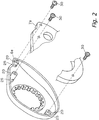
- Fig. 2 is an exploded oblique, partly fragmentary view of a first side cover mounting environment;
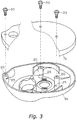
- Fig. 3 is an exploded oblique, partly fragmentary view of a second side cover mounting environment;
- Fig. 4 is a fragmentary enlarged oblique view of a protrusion portion;
- Fig. 5 is a typifying diagram of an enlarged fragmentary section of the reel body;
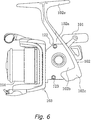
- Fig. 6 is a lateral view of a spinning reel in which a second embodiment of the present invention is adapted;
- Fig. 7 is a sectional view of the Fig. 6 spinning reel;
- Fig. 8 is an enlarged fragmentary sectional view of the environment of a first screw portion;
- Fig. 9 is a fragmentary sectional view along IX - IX in Fig. 7;
- Fig. 10 is a sectional view along X - X in Fig. 7;
- Fig. 11 is a fragmentary enlarged oblique view of a protrusion portion in another embodiment;
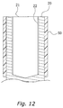
- Fig. 12 is a fragmentary enlarged sectional view of a protrusion portion in another embodiment; and
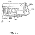
- Fig. 13 is a fragmentary enlarged sectional view of the environment of a first screw portion in another embodiment.
-
- As shown in Fig. 1, the dual-bearing reel in accordance with the first embodiment of the present invention is a low profile reel for bait-casting. This dual-bearing reel includes a
reel body 1, ahandle assembly 2 for turning a spool, and aspool 4 for winding fishing line. Thehandle assembly 2 is disposed on one side of thereel body 1. Thespool 4 is provided rotatably and detachably inside thereel body 1. Astar drag 3 for adjusting drag is disposed on the same side of thereel body 1 as thehandle 2. - The
reel body 1 includes aframe 5, and afirst side cover 6a and asecond side cover 6b attached to the two sides of theframe 5. Theframe 5 includes afirst side plate 7a and asecond side plate 7b to which thefirst side cover 6a and thesecond side cover 6b are attached, and a plurality of connecting portions 8 connecting thefirst side plate 7a with thesecond side plate 7b into one unit. - As shown in Figs. 2 and 3, the
first side cover 6a and thesecond side cover 6b are fastened withscrews 30 from the inside of thefirst side plate 7a and thesecond side plate 7b to a plurality ofprotrusion portions 20 protruding on the rear side of thefirst side cover 6a and thesecond side cover 6b. Therefore, the screw terminals are not exposed to the surface side of thefirst side cover 6a and thesecond side cover 6b. - As shown enlarged in Fig. 4, the
protrusion portion 20 includes arecess portion 22 in which female threads are formed and having anopening 21 at its tip end, and aconduit 25 formed base-endward communicating therecess portion 22 with its exterior. Theconduit 25 is a slit arranged in a direction perpendicular to the direction in which theprotrusion portion 20 protrudes (that is, horizontally), and is machined, for example with a with a T-slot cutter, so as to be communicated with therecess portion 22. - The members constituting the reel body 1 (in the following collectively referred to as main components 10) are made of a magnesium alloy. A coating is applied to the surface of the
main components 10. - As shown in Fig. 5, an anodic
oxide film layer 11 is formed by anodic oxidation on the surface of themain components 10 made of magnesium alloy. Anelectrodeposition film layer 12 is formed by electrodeposition on the surface of the anodicoxide film layer 11. - Taking the
main components 10 as the anode, the anodicoxide film layer 11 is electrolytically decomposed in a solution of sulfuric acid, oxalic acid or chromic acid, and a film is formed due to oxygen generated at the anode. - The
electrodeposition film layer 12 is formed by electrodeposition using a cationic electrodeposition paint, whose main component is a polyamine resin. To carry out the electrodeposition, themain components 10 which have been coated with the anodicoxide film layer 11 are immersed in a bath of the electrodeposition paint, and taking themain components 10 as the cathode and electrodes arranged in the bath of the electrodeposition paint as the anode, themain components 10 are electrolytically coated with the paint by applying a dc voltage. - To paint the
main components 10 by electrodeposition, it is necessary to machine themain components 10 in a cutting process first. For example, thefirst side cover 6a and thesecond side cover 6b, which are two of themain components 10, are painted after forming the recess portion 22 (hole and female thread) and theconduit 25 in theprotrusion portion 20. - In the
first side cover 6a and thesecond side cover 6b of this dual-bearing reel, theprotrusion portions 20 are provided with theconduits 25 communicated with therecess portions 22, so that when they are painted by electrodeposition, excess paint is discharged through theconduits 25 to the outside, preventing a build-up of paint in therecess portions 22. - As shown in Fig. 6, a spinning reel in accordance with the second embodiment of the present invention includes a
handle 101, areel body 102 rotatively supporting thehandle 1, arotor 103, and aspool 104. Therotor 103 is rotatively supported at the front of thereel body 102. The fishing line is wound around the outer peripheral surface of thespool 104, which is disposed at the front of therotor 103 and can be shifted back and forth. - The
reel body 102 includes areel body 102a provided with a space inside, alid member 102b and acover member 102c mounted detachably to thereel body 102a to shut the space in thereel body 102a, and a bearingmember 102d (see Fig. 10) for mounting a rotation transmission mechanism 114 described below. - The
reel body 102a is made, for example, of a magnesium alloy, and is formed unitarily with a T-shapedrod attachment leg 102e extending horizontally at the top of thereel body 102a. As shown in Fig. 7, the space in thereel body 102a accommodates arotor driving mechanism 105 for transmitting the rotation of thehandle 101 to rotate therotor 103, and anoscillation mechanism 106 for winding up the fishing line uniformly by shifting thespool 104 back and forth. - The
lid member 102b is made, for example, of a magnesium alloy, and screwed at three locations to the left side of thereel body 102a at asecond screw portion 122, athird screw portion 123, and afourth screw portion 124, as shown in Figs. 6 and 7. - The
cover member 102c, which is for example made of a magnesium alloy, covers the rear end portion of thereel body 102a and is fastened at afirst screw portion 121 to thereel body 102a at the upper rear. - As shown in Fig. 7, the
rotor driving mechanism 105 includes ahandle shaft 110, aface gear 111 and apinion gear 112. Theface gear 111 rotates together with thehandle shaft 110, on which thehandle 101 is mounted non-rotatively. Thepinion gear 112 meshes with theface gear 111. Thepinion gear 112 is tubular. Its front portion 112a penetrates the center of therotor 103, and is fixed with a nut to therotor 103. The middle and the rear end (with respect to the axial direction) of thepinion gear 112 are rotatively supported by bearings in thereel body 102. - The
oscillation mechanism 106 shifts thespool 104 back and forth, shifting back and forth thespool shaft 115 to which the center of thespool 104 is coupled via adrag mechanism 160. - As shown in Fig. 7, the
rotor 103 includes arotor unit 116, abail arm 117, and abail flipping mechanism 118. Thebail arm 117 is disposed to the front of therotor unit 116 and is pivotable between a line-releasing position and a line-winding position. Thebail flipping mechanism 118 is mounted to therotor unit 116 and is for returning thebail arm 117 into the line-winding position. - The
rotor unit 116 includes acylindrical portion 130, afirst rotor arm 131 and asecond rotor arm 132. Thecylindrical portion 130 is attached to thereel body 102a and can rotate freely around thespool shaft 115. Thefirst rotor arm 131 and thesecond rotor arm 132 are arranged in opposition to one another on the sides of thecylindrical portion 130. Thecylindrical portion 130, thefirst rotor arm 131 and thesecond rotor arm 132 can be made, for example, of an magnesium alloy, and are formed in one piece. - As shown in Figs. 6 and 7, the first and
second rotor arms second connection portions cylindrical portion 130, first andsecond arm portions second connection portions second cover members connection portions arm portions second connection portions cylindrical portion 130. First and secondbail support members second arm portions - As shown in Fig. 7, a
line roller 141 for guiding fishing line to thespool 104, and a fixedshaft cover 147 are fixed to the front of the firstbail support member 140, with theline roller 141 being arranged between the firstbail support member 140 and the fixedshaft cover 147. Theline roller 141 is mounted rotatively to the front end of the firstbail support member 140. The fixedshaft cover 147 is shaped like a deformed cone with a sharply tapering tip. Abail 143, made by bending a wire into U-shape, is fixed between the tip of the fixedshaft cover 147 and the secondbail support member 142. The first and secondbail support members line roller 141, thebail 143, and the fixedshaft cover 147 constitute thebail arm 117, which guides the fishing line to thespool 104. - The following is a detailed explanation of the configuration of the first to
third screw portions 121 to 123 of thereel body 102a. - As shown enlarged in Fig. 8, the
first screw portion 121 includes afirst recess portion 121b and afirst conduit 121c communicating the first recess portion with its exterior. Thefirst recess portion 121b has afirst opening 121a and is formed at an upper rear portion of thereel body 102a. The inner wall of thefirst recess portion 121b is provided with a female thread, and thecover member 102c is fastened to thereel body 102a by screwing ascrew 180 into thefirst recess portion 121b. Thereel body 102a and thecover member 102c are provided with indentations, which accommodate the head of thescrew 180 so that it does not stick out from the outer peripheral surface of thecover member 102c. - The
cover member 102c is a shutoff between thefirst conduit 121c its exterior. Thefirst conduit 121c is provided with an aperture on the same side as thefirst opening 121a. Furthermore, thefirst conduit 121c is formed such that thefirst recess portion 121b does not bore through thereel body 102a. - As shown enlarged in Fig. 9, the
second screw portion 122 includes asecond recess portion 122b and asecond conduit 122c communicating thesecond recess portion 122b with its exterior (that is, with the inside of the reel body 102). Thesecond recess portion 122b has asecond opening 122a and is formed on the upper left side of thereel body 102a. The inner wall of thesecond recess portion 122b is provided with a female thread, and thelid member 102b is fastened to thereel body 102a by screwing ascrew 180 into thesecond recess portion 122b. Thesecond conduit 122c is formed base-endward of thesecond recess portion 122b. - As shown enlarged in Fig. 10, the
third screw portion 123 includes athird recess portion 123b and athird conduit 123c communicating thethird recess portion 123b with its exterior (that is, an aperture to the side of the bearingmember 102d on which the rotation transmission mechanism 114 is mounted). Thethird recess portion 123b has athird opening 123a and is formed on the lower left side of thereel body 102a. The rotation transmission mechanism 14 includes apinion gear 112 mounted on thespool shaft 115, a linkingshaft 114a, a bearingmember 102d which rotatably supports the lower end of the linkingshaft 114a, a bearing member which rotatably supports the upper end of the linkingshaft 114a, and first tothird gears 114b to 114d. The inner wall of thethird recess portion 123b is provided with a female thread, and thelid member 102b is fastened to thereel body 102a by screwing ascrew 180 into thethird recess portion 123b. Thethird conduit 123c is communicated with the exterior thereof through the lower end of thethird recess portion 123b. - All components of the
reel body 102a are made of a magnesium alloy, and as in the first embodiment, they are painted by electrodeposition after the screw holes have been formed. The details of the electrodeposition are the same as in the first embodiment, so that their further explanation has been omitted. - In a spinning reel with this configuration, the
reel body 102a is provided with first tothird conduits 121c to 123c communicating with the first tothird recess portions 121b to 123b, so that when it is painted by electrodeposition, excess paint is discharged from the first to third conduits 121d to 123d to the outside, preventing a build-up of paint in the first tothird recess portions 121c to 123c. -
- (a) The first and second embodiments have been explained taking a dual-bearing reel and a spinning reel as examples of paint-coated fishing components, but they are not thereby limited, and the present invention can be applied also to single-bearing reels or any other kind of fishing reel.
- (b) In the first and second embodiments, the
main components 10 are made of a magnesium alloy, but they can also be made of an aluminum alloy a titanium alloy or any other suitable metal. - (c) In the first embodiment, the
conduit 25 is formed as a horizontal slit in theprotrusion portion 20, but it is not thereby limited, and the conduit may also be formed as a vertical slit. Moreover, as shown in Fig. 11, theconduit 25 can also be formed as a vertical slot extending from theopening 21. On the other hand, it is also possible to provide areinforcement member 50 made of a synthetic resin can be disposed around theprotrusion portion 20, as shown in Fig. 12. Here, thereinforcement member 50 functions as thecover member 102c of the second embodiment. - (d) In the
third screw portion 123 of the second embodiment, thethird conduit 123c was formed such that it communicates thethird recess portion 123b with the opening on the side of the bearingmember 102d, to which the rotation transmission mechanism 114 is mounted. However, it is also possible to form thethird conduit 123c by letting thescrew hole 123d for mounting theguide shaft 106a of theoscillation mechanism 106 penetrate all the way to thethird recess portion 123b, as shown in Fig. 13. -
- According to the present invention, in a painted fishing gear component having a main part provided with a recess portion, the main part is provided with a conduit communicating the recess portion with its exterior, so that excess paint is discharged from the conduit to the outside, preventing a build-up of paint in the recess portion.
- While only selected embodiments have been chosen to illustrate the present invention, to those skilled in the art it will be apparent from this disclosure that various changes and modifications can be made herein without departing from the scope of the invention as defined in the appended claims. Furthermore, the foregoing description of the embodiments according to the present invention is provided for illustration only, and not for the purpose of limiting the invention as defined by the appended claims.
Claims (17)
- A paint-coated fishing component for use in fishing reels, the paint-coated fishing component comprising:a main component including a body portion, a recessed portion (22) formed on said body portion and having an opening (21), and a conduit (25) formed on said body portion and communicating said recessed portion (22) with its exterior; anda paint layer formed by immersing said main component in paint.
- A paint-coated fishing component as claimed in Claim 1, wherein said body portion further has protrusion portion (20) whose tip end has said opening (21) and in which said conduit (25) and said recess portion (22) are formed.
- A paint-coated fishing component as claimed in Claim 1 or Claim 2, wherein said paint layer is an electrodeposition paint layer (12) formed by an electrodeposition coating method.
- A paint-coated fishing component as claimed in Claim 3, further comprising an anodic oxide film layer (11) between said main component and said electrodeposition paint layer (12).
- A paint-coated fishing component as claimed in any of Claims 2 to 4, wherein said conduit (25) is a slit formed in said protrusion portion (20).
- A paint-coated fishing component as claimed in any of Claims 2 to 5 wherein said conduit (25) is formed base-endward in said protrusion portion (20).
- A paint-coated fishing component as claimed in any of Claims 2 to 5, wherein said conduit (25) is formed extending from said opening (21) in said protrusion portion (20) toward its base end.
- A paint-coated fishing component as claimed in any preceding Claim, wherein the conduit (25) is formed by cutting work.
- A paint-coated fishing component as claimed in any preceding Claim, wherein said main component is made of an alloy selected from the group consisting of magnesium alloys, aluminium alloys and titanium alloys.
- A paint-coated fishing component as claimed in any preceding Claim, wherein the main component is a side cover (6a, 6b) attached to a fishing reel frame (5).
- A paint-coated fishing component as claimed in Claim 10, wherein:said side cover (6a, 6b) is fixed by a screw (30) to the frame (5);said protrusion portion (20) is a boss into which the screw is mounted; andsaid recess portion (22) is formed with female threads into which the screw (30) screw-mates.
- A paint-coated fishing component as claimed in any preceding Claim further comprising a reinforcement member (50) attached to said protrusion portion (20).
- A paint-coated fishing component as claimed in any preceding Claim, further comprising a cover member (102c) as a shutoff between said conduit (121c) and its exterior.
- A paint-coated fishing component as claimed in any preceding Claim, wherein said conduit opens the same way as said opening.
- A paint-coated fishing component as claimed in any proceeding Claim, wherein said conduit (121c) is formed such that said recess portion (121b) does not bore through said body portion.
- A paint coated fishing component as claimed in any preceding Claim, wherein said main component is the reel body portion (102) of a fishing reel.
- A paint-coated fishing component as claimed in Claim 16, wherein a boss to which another member can be fixed by screw-fastening is formed on said reel body portion (1, 102).
Applications Claiming Priority (4)
| Application Number | Priority Date | Filing Date | Title |
|---|---|---|---|
| JP2000144404 | 2000-05-17 | ||
| JP2000144404 | 2000-05-17 | ||
| JP2000271606A JP3772265B2 (en) | 2000-05-17 | 2000-09-07 | Painted parts for fishing |
| JP2000271606 | 2000-09-07 |
Publications (2)
| Publication Number | Publication Date |
|---|---|
| EP1155612A1 true EP1155612A1 (en) | 2001-11-21 |
| EP1155612B1 EP1155612B1 (en) | 2005-07-27 |
Family
ID=26592013
Family Applications (1)
| Application Number | Title | Priority Date | Filing Date |
|---|---|---|---|
| EP01303995A Expired - Lifetime EP1155612B1 (en) | 2000-05-17 | 2001-05-01 | Coated fishing components |
Country Status (10)
| Country | Link |
|---|---|
| US (1) | US6464159B2 (en) |
| EP (1) | EP1155612B1 (en) |
| JP (1) | JP3772265B2 (en) |
| KR (1) | KR100687896B1 (en) |
| CN (1) | CN1188033C (en) |
| AT (1) | ATE300173T1 (en) |
| DE (1) | DE60112170T2 (en) |
| MY (1) | MY118534A (en) |
| SG (1) | SG96616A1 (en) |
| TW (1) | TW496726B (en) |
Cited By (3)
| Publication number | Priority date | Publication date | Assignee | Title |
|---|---|---|---|---|
| EP1514472A1 (en) * | 2003-09-12 | 2005-03-16 | Shimano Inc. | Reel unit for a dual bearing reel |
| CN103081875A (en) * | 2011-11-08 | 2013-05-08 | 株式会社岛野 | Fishing-reel reel unit and fishing reel |
| EP2898771A1 (en) * | 2014-01-23 | 2015-07-29 | Shimano Inc. | Fishing reel |
Families Citing this family (10)
| Publication number | Priority date | Publication date | Assignee | Title |
|---|---|---|---|---|
| JP2002267028A (en) * | 2001-03-07 | 2002-09-18 | Shimano Inc | Parts assembly |
| JP2004082612A (en) | 2002-08-28 | 2004-03-18 | Shimano Inc | Outdoor appearance parts |
| JP4535742B2 (en) * | 2004-02-03 | 2010-09-01 | 株式会社シマノ | Fishing reel, fishing information display device and fishing information display system |
| US20080216383A1 (en) * | 2007-03-07 | 2008-09-11 | David Pierick | High performance nano-metal hybrid fishing tackle |
| CN101423967B (en) * | 2007-10-31 | 2011-05-18 | 比亚迪股份有限公司 | Surface treating method of aluminum alloy material |
| JP5906017B2 (en) * | 2011-01-28 | 2016-04-20 | グローブライド株式会社 | Reel for fishing, component for fishing reel, and manufacturing method thereof |
| JP6209310B2 (en) * | 2012-01-18 | 2017-10-04 | 株式会社シマノ | Double bearing reel and its drive shaft |
| US11076585B2 (en) * | 2016-01-27 | 2021-08-03 | Globeride, Inc. | Fishing line guide having high-hardness surface layer and fishing rod provided with said fishing line guide |
| JP6796006B2 (en) * | 2017-03-03 | 2020-12-02 | シマノコンポネンツ マレーシア エスディーエヌ.ビーエッチディー. | Fishing reel handle |
| JP7267081B2 (en) * | 2018-07-13 | 2023-05-01 | 株式会社シマノ | Speed reducer for electric reel, method for manufacturing speed reducer for electric reel, and electric reel for fishing |
Citations (3)
| Publication number | Priority date | Publication date | Assignee | Title |
|---|---|---|---|---|
| US2885108A (en) * | 1957-10-25 | 1959-05-05 | Robert J Donoghue | Paint can closure means |
| JPS57121977A (en) * | 1981-01-19 | 1982-07-29 | Mazda Motor Corp | Shaping method for floor panel paint discharge hole and its lid of car body |
| EP0594955A2 (en) * | 1992-09-25 | 1994-05-04 | Dr.Ing.h.c. F. Porsche Aktiengesellschaft | Side panel for motor vehicles |
Family Cites Families (9)
| Publication number | Priority date | Publication date | Assignee | Title |
|---|---|---|---|---|
| US4268324A (en) * | 1979-04-20 | 1981-05-19 | Sharma Vinod C | Fabrication of spectrally selective solar surfaces by the thermal treatment of austenitic stainless steel AISI 321 |
| US4905930A (en) * | 1985-07-22 | 1990-03-06 | Zebco Corporation | Bait casting fishing reel |
| US5156720A (en) * | 1989-02-02 | 1992-10-20 | Alcan International Limited | Process for producing released vapor deposited films and product produced thereby |
| SE500229C2 (en) * | 1991-10-02 | 1994-05-09 | Boerje Jansson | Locking element |
| US5662443A (en) * | 1996-04-08 | 1997-09-02 | Illinois Tool Works Inc. | Prevailing torque nut |
| JPH10263177A (en) | 1997-03-21 | 1998-10-06 | Amtex Kk | Pachinko playground management system |
| US5915902A (en) * | 1997-09-19 | 1999-06-29 | Illinois Tool Works Inc. | Undeformed lock nut with slot |
| JP2000083534A (en) * | 1998-09-17 | 2000-03-28 | Shimano Inc | Fishing reel spool |
| KR200174209Y1 (en) * | 1999-05-21 | 2000-03-15 | 주식회사신아스포츠 | Bait casting reel having spool detaching mechanism |
-
2000
- 2000-09-07 JP JP2000271606A patent/JP3772265B2/en not_active Expired - Fee Related
-
2001
- 2001-03-01 TW TW090104759A patent/TW496726B/en not_active IP Right Cessation
- 2001-03-30 KR KR1020010017018A patent/KR100687896B1/en not_active Expired - Fee Related
- 2001-04-26 SG SG200102372A patent/SG96616A1/en unknown
- 2001-04-27 US US09/842,950 patent/US6464159B2/en not_active Expired - Lifetime
- 2001-05-01 EP EP01303995A patent/EP1155612B1/en not_active Expired - Lifetime
- 2001-05-01 DE DE60112170T patent/DE60112170T2/en not_active Expired - Lifetime
- 2001-05-01 AT AT01303995T patent/ATE300173T1/en not_active IP Right Cessation
- 2001-05-02 MY MYPI20012044A patent/MY118534A/en unknown
- 2001-05-17 CN CNB011195207A patent/CN1188033C/en not_active Expired - Lifetime
Patent Citations (3)
| Publication number | Priority date | Publication date | Assignee | Title |
|---|---|---|---|---|
| US2885108A (en) * | 1957-10-25 | 1959-05-05 | Robert J Donoghue | Paint can closure means |
| JPS57121977A (en) * | 1981-01-19 | 1982-07-29 | Mazda Motor Corp | Shaping method for floor panel paint discharge hole and its lid of car body |
| EP0594955A2 (en) * | 1992-09-25 | 1994-05-04 | Dr.Ing.h.c. F. Porsche Aktiengesellschaft | Side panel for motor vehicles |
Non-Patent Citations (1)
| Title |
|---|
| PATENT ABSTRACTS OF JAPAN vol. 006, no. 216 (M - 168) 29 October 1982 (1982-10-29) * |
Cited By (6)
| Publication number | Priority date | Publication date | Assignee | Title |
|---|---|---|---|---|
| EP1514472A1 (en) * | 2003-09-12 | 2005-03-16 | Shimano Inc. | Reel unit for a dual bearing reel |
| US7150423B2 (en) | 2003-09-12 | 2006-12-19 | Shimano Inc. | Reel unit for a dual bearing reel |
| CN103081875A (en) * | 2011-11-08 | 2013-05-08 | 株式会社岛野 | Fishing-reel reel unit and fishing reel |
| EP2591670A1 (en) * | 2011-11-08 | 2013-05-15 | Shimano Inc. | Fishing-reel reel unit and fishing reel |
| US8985493B2 (en) | 2011-11-08 | 2015-03-24 | Shimano Inc. | Fishing-reel reel unit and fishing reel |
| EP2898771A1 (en) * | 2014-01-23 | 2015-07-29 | Shimano Inc. | Fishing reel |
Also Published As
| Publication number | Publication date |
|---|---|
| CN1188033C (en) | 2005-02-09 |
| ATE300173T1 (en) | 2005-08-15 |
| JP3772265B2 (en) | 2006-05-10 |
| KR20010106174A (en) | 2001-11-29 |
| MY118534A (en) | 2004-11-30 |
| EP1155612B1 (en) | 2005-07-27 |
| CN1323521A (en) | 2001-11-28 |
| DE60112170T2 (en) | 2006-05-24 |
| SG96616A1 (en) | 2003-06-16 |
| TW496726B (en) | 2002-08-01 |
| JP2002034401A (en) | 2002-02-05 |
| US20010042805A1 (en) | 2001-11-22 |
| DE60112170D1 (en) | 2005-09-01 |
| US6464159B2 (en) | 2002-10-15 |
| KR100687896B1 (en) | 2007-02-27 |
Similar Documents
| Publication | Publication Date | Title |
|---|---|---|
| EP1155612B1 (en) | Coated fishing components | |
| EP2272334B1 (en) | Fishing reel handle assembly | |
| US7374119B2 (en) | Handle knob and handle assembly for a fishing reel | |
| US6902127B2 (en) | Reel unit for spinning reel | |
| US7118059B2 (en) | Reel unit for spinning reel | |
| EP1304032A2 (en) | Fastening structure for fishing equipment parts | |
| US7014135B2 (en) | Fishing reel | |
| KR101044322B1 (en) | Reel Body of Double Bearing Reel | |
| US7665683B2 (en) | Fishing line guiding mechanism of spinning reel | |
| EP1629713B1 (en) | Spinning-reel sounding mechanism | |
| US6966515B2 (en) | Handle attachment structure for fishing reel | |
| EP1413195B1 (en) | Reel unit for spinning reel | |
| EP1108355A1 (en) | Spinning reel spool | |
| EP1407662B1 (en) | Fishing line guide mechanism for spinning reel | |
| JP4324490B2 (en) | Painted parts for fishing | |
| US7077349B2 (en) | Fishing line guide mechanism for spinning reel | |
| EP1474974B1 (en) | Fishing line guide mechanism for a spinning reel and method of the same | |
| JP2000333565A (en) | Fishing reel cover | |
| EP2898771A1 (en) | Fishing reel | |
| JPH11332428A (en) | Surface structure of fishing gear | |
| JP2002335821A (en) | Spinning reel reel body | |
| JP2001321039A (en) | Spinning reel face gear |
Legal Events
| Date | Code | Title | Description |
|---|---|---|---|
| PUAI | Public reference made under article 153(3) epc to a published international application that has entered the european phase |
Free format text: ORIGINAL CODE: 0009012 |
|
| AK | Designated contracting states |
Kind code of ref document: A1 Designated state(s): AT BE CH CY DE DK ES FI FR GB GR IE IT LI LU MC NL PT SE TR |
|
| AX | Request for extension of the european patent |
Free format text: AL;LT;LV;MK;RO;SI |
|
| 17P | Request for examination filed |
Effective date: 20020208 |
|
| AKX | Designation fees paid |
Free format text: AT BE CH CY DE DK ES FI FR GB GR IE IT LI LU MC NL PT SE TR |
|
| GRAP | Despatch of communication of intention to grant a patent |
Free format text: ORIGINAL CODE: EPIDOSNIGR1 |
|
| GRAS | Grant fee paid |
Free format text: ORIGINAL CODE: EPIDOSNIGR3 |
|
| GRAA | (expected) grant |
Free format text: ORIGINAL CODE: 0009210 |
|
| AK | Designated contracting states |
Kind code of ref document: B1 Designated state(s): AT BE CH CY DE DK ES FI FR GB GR IE IT LI LU MC NL PT SE TR |
|
| PG25 | Lapsed in a contracting state [announced via postgrant information from national office to epo] |
Ref country code: BE Free format text: LAPSE BECAUSE OF FAILURE TO SUBMIT A TRANSLATION OF THE DESCRIPTION OR TO PAY THE FEE WITHIN THE PRESCRIBED TIME-LIMIT Effective date: 20050727 Ref country code: CH Free format text: LAPSE BECAUSE OF FAILURE TO SUBMIT A TRANSLATION OF THE DESCRIPTION OR TO PAY THE FEE WITHIN THE PRESCRIBED TIME-LIMIT Effective date: 20050727 Ref country code: TR Free format text: LAPSE BECAUSE OF FAILURE TO SUBMIT A TRANSLATION OF THE DESCRIPTION OR TO PAY THE FEE WITHIN THE PRESCRIBED TIME-LIMIT Effective date: 20050727 Ref country code: LI Free format text: LAPSE BECAUSE OF FAILURE TO SUBMIT A TRANSLATION OF THE DESCRIPTION OR TO PAY THE FEE WITHIN THE PRESCRIBED TIME-LIMIT Effective date: 20050727 Ref country code: NL Free format text: LAPSE BECAUSE OF FAILURE TO SUBMIT A TRANSLATION OF THE DESCRIPTION OR TO PAY THE FEE WITHIN THE PRESCRIBED TIME-LIMIT Effective date: 20050727 Ref country code: FI Free format text: LAPSE BECAUSE OF FAILURE TO SUBMIT A TRANSLATION OF THE DESCRIPTION OR TO PAY THE FEE WITHIN THE PRESCRIBED TIME-LIMIT Effective date: 20050727 Ref country code: AT Free format text: LAPSE BECAUSE OF FAILURE TO SUBMIT A TRANSLATION OF THE DESCRIPTION OR TO PAY THE FEE WITHIN THE PRESCRIBED TIME-LIMIT Effective date: 20050727 |
|
| REG | Reference to a national code |
Ref country code: GB Ref legal event code: FG4D |
|
| REG | Reference to a national code |
Ref country code: CH Ref legal event code: EP |
|
| REG | Reference to a national code |
Ref country code: IE Ref legal event code: FG4D |
|
| REF | Corresponds to: |
Ref document number: 60112170 Country of ref document: DE Date of ref document: 20050901 Kind code of ref document: P |
|
| PG25 | Lapsed in a contracting state [announced via postgrant information from national office to epo] |
Ref country code: GR Free format text: LAPSE BECAUSE OF FAILURE TO SUBMIT A TRANSLATION OF THE DESCRIPTION OR TO PAY THE FEE WITHIN THE PRESCRIBED TIME-LIMIT Effective date: 20051027 Ref country code: DK Free format text: LAPSE BECAUSE OF FAILURE TO SUBMIT A TRANSLATION OF THE DESCRIPTION OR TO PAY THE FEE WITHIN THE PRESCRIBED TIME-LIMIT Effective date: 20051027 Ref country code: SE Free format text: LAPSE BECAUSE OF FAILURE TO SUBMIT A TRANSLATION OF THE DESCRIPTION OR TO PAY THE FEE WITHIN THE PRESCRIBED TIME-LIMIT Effective date: 20051027 |
|
| PG25 | Lapsed in a contracting state [announced via postgrant information from national office to epo] |
Ref country code: PT Free format text: LAPSE BECAUSE OF FAILURE TO SUBMIT A TRANSLATION OF THE DESCRIPTION OR TO PAY THE FEE WITHIN THE PRESCRIBED TIME-LIMIT Effective date: 20051227 |
|
| REG | Reference to a national code |
Ref country code: CH Ref legal event code: PL |
|
| NLV1 | Nl: lapsed or annulled due to failure to fulfill the requirements of art. 29p and 29m of the patents act | ||
| PG25 | Lapsed in a contracting state [announced via postgrant information from national office to epo] |
Ref country code: IE Free format text: LAPSE BECAUSE OF NON-PAYMENT OF DUE FEES Effective date: 20060501 |
|
| PG25 | Lapsed in a contracting state [announced via postgrant information from national office to epo] |
Ref country code: MC Free format text: LAPSE BECAUSE OF NON-PAYMENT OF DUE FEES Effective date: 20060531 |
|
| PLBE | No opposition filed within time limit |
Free format text: ORIGINAL CODE: 0009261 |
|
| STAA | Information on the status of an ep patent application or granted ep patent |
Free format text: STATUS: NO OPPOSITION FILED WITHIN TIME LIMIT |
|
| 26N | No opposition filed |
Effective date: 20060428 |
|
| EN | Fr: translation not filed | ||
| PG25 | Lapsed in a contracting state [announced via postgrant information from national office to epo] |
Ref country code: FR Free format text: LAPSE BECAUSE OF FAILURE TO SUBMIT A TRANSLATION OF THE DESCRIPTION OR TO PAY THE FEE WITHIN THE PRESCRIBED TIME-LIMIT Effective date: 20060922 |
|
| REG | Reference to a national code |
Ref country code: IE Ref legal event code: MM4A |
|
| PG25 | Lapsed in a contracting state [announced via postgrant information from national office to epo] |
Ref country code: LU Free format text: LAPSE BECAUSE OF NON-PAYMENT OF DUE FEES Effective date: 20060501 |
|
| PG25 | Lapsed in a contracting state [announced via postgrant information from national office to epo] |
Ref country code: CY Free format text: LAPSE BECAUSE OF FAILURE TO SUBMIT A TRANSLATION OF THE DESCRIPTION OR TO PAY THE FEE WITHIN THE PRESCRIBED TIME-LIMIT Effective date: 20050727 Ref country code: FR Free format text: LAPSE BECAUSE OF FAILURE TO SUBMIT A TRANSLATION OF THE DESCRIPTION OR TO PAY THE FEE WITHIN THE PRESCRIBED TIME-LIMIT Effective date: 20050727 |
|
| PG25 | Lapsed in a contracting state [announced via postgrant information from national office to epo] |
Ref country code: ES Free format text: LAPSE BECAUSE OF NON-PAYMENT OF DUE FEES Effective date: 20060531 |
|
| PGFP | Annual fee paid to national office [announced via postgrant information from national office to epo] |
Ref country code: IT Payment date: 20110513 Year of fee payment: 11 |
|
| PG25 | Lapsed in a contracting state [announced via postgrant information from national office to epo] |
Ref country code: IT Free format text: LAPSE BECAUSE OF NON-PAYMENT OF DUE FEES Effective date: 20120501 |
|
| PGFP | Annual fee paid to national office [announced via postgrant information from national office to epo] |
Ref country code: DE Payment date: 20200422 Year of fee payment: 20 |
|
| PGFP | Annual fee paid to national office [announced via postgrant information from national office to epo] |
Ref country code: GB Payment date: 20200422 Year of fee payment: 20 |
|
| REG | Reference to a national code |
Ref country code: DE Ref legal event code: R071 Ref document number: 60112170 Country of ref document: DE |
|
| REG | Reference to a national code |
Ref country code: GB Ref legal event code: PE20 Expiry date: 20210430 |
|
| PG25 | Lapsed in a contracting state [announced via postgrant information from national office to epo] |
Ref country code: GB Free format text: LAPSE BECAUSE OF EXPIRATION OF PROTECTION Effective date: 20210430 |