EP1154677A2 - System and method for operating incandescent lamps with high voltage source - Google Patents
System and method for operating incandescent lamps with high voltage source Download PDFInfo
- Publication number
- EP1154677A2 EP1154677A2 EP01302906A EP01302906A EP1154677A2 EP 1154677 A2 EP1154677 A2 EP 1154677A2 EP 01302906 A EP01302906 A EP 01302906A EP 01302906 A EP01302906 A EP 01302906A EP 1154677 A2 EP1154677 A2 EP 1154677A2
- Authority
- EP
- European Patent Office
- Prior art keywords
- lamp
- generator
- pwm
- pulse width
- width modulation
- Prior art date
- Legal status (The legal status is an assumption and is not a legal conclusion. Google has not performed a legal analysis and makes no representation as to the accuracy of the status listed.)
- Granted
Links
- 238000000034 method Methods 0.000 title claims abstract description 19
- 230000003247 decreasing effect Effects 0.000 claims description 2
- 238000012544 monitoring process Methods 0.000 description 2
- 239000004065 semiconductor Substances 0.000 description 2
- 230000001276 controlling effect Effects 0.000 description 1
- 238000010586 diagram Methods 0.000 description 1
- 230000000694 effects Effects 0.000 description 1
- 230000001105 regulatory effect Effects 0.000 description 1
Images
Classifications
-
- H—ELECTRICITY
- H05—ELECTRIC TECHNIQUES NOT OTHERWISE PROVIDED FOR
- H05B—ELECTRIC HEATING; ELECTRIC LIGHT SOURCES NOT OTHERWISE PROVIDED FOR; CIRCUIT ARRANGEMENTS FOR ELECTRIC LIGHT SOURCES, IN GENERAL
- H05B39/00—Circuit arrangements or apparatus for operating incandescent light sources
- H05B39/04—Controlling
- H05B39/041—Controlling the light-intensity of the source
- H05B39/044—Controlling the light-intensity of the source continuously
- H05B39/047—Controlling the light-intensity of the source continuously with pulse width modulation from a DC power source
-
- Y—GENERAL TAGGING OF NEW TECHNOLOGICAL DEVELOPMENTS; GENERAL TAGGING OF CROSS-SECTIONAL TECHNOLOGIES SPANNING OVER SEVERAL SECTIONS OF THE IPC; TECHNICAL SUBJECTS COVERED BY FORMER USPC CROSS-REFERENCE ART COLLECTIONS [XRACs] AND DIGESTS
- Y02—TECHNOLOGIES OR APPLICATIONS FOR MITIGATION OR ADAPTATION AGAINST CLIMATE CHANGE
- Y02B—CLIMATE CHANGE MITIGATION TECHNOLOGIES RELATED TO BUILDINGS, e.g. HOUSING, HOUSE APPLIANCES OR RELATED END-USER APPLICATIONS
- Y02B20/00—Energy efficient lighting technologies, e.g. halogen lamps or gas discharge lamps
Definitions
- the present invention relates generally to incandescent lamps for motor vehicles and, more specifically, to a system and method for operating designed-for low voltage incandescent lamps with a high voltage source for a motor vehicle.
- Redesigning electrical loads for a higher voltage is generally not a problem for motors, relays and other components in a motor vehicle.
- the incandescent lamps are an exception. Redesigning the incandescent lamps for three times the voltage would necessitate going to nine times the resistance for the same wattage lamp. That would mean that the cross-sectional area of the lamp filament would have to be reduced by a factor of three and the length of the filament would have to be increased to three times.
- a disadvantage of the smaller filament diameter is that the incandescent lamp has a much shorter lamp life due to the effect of mechanical vibrations causing a smaller diameter lamp filament to break sooner. From the point of the life and durability of the incandescent lamp for motor vehicle applications, a lamp design for 12.8v or better yet, one designed for 6.4v, would be preferred by motor vehicle manufacturers in terms of lower warranty cost and higher customer satisfaction.
- the present invention is a system and method for operating incandescent lamps with a higher voltage source than it was designed for in a motor vehicle.
- the system includes at least one pulse width modulation circuit having an incandescent lamp electrically connected to a high voltage source.
- the system also includes a generator electrically connected to the at least one pulse width modulation circuit for generating a pulse width modulation signal to modulate a voltage of the high voltage source to a voltage rating of the incandescent lamp.
- One advantage of the present invention is that a new system and method for operating or driving incandescent lamps with a high voltage source is provided for a motor vehicle.
- Another advantage of the present invention is that the system and method enables 12.8v rated incandescent lamps to be operated from a higher voltage source of 38.4v without the use of a DC-to-DC converter to convert the voltage down to 12.8v.
- Yet another advantage of the present invention is that the system and method uses a pulse width modulation (PWM) of the voltage supplied to the incandescent lamps to convert the voltage down to the rms voltage rating of the incandescent lamp.
- PWM pulse width modulation
- Still another advantage of the present invention is that the system and method provides a simpler and lower cost solution for powering the incandescent lamps in vehicle wherein a higher voltage system such as 38.4v is in place and where a 12v source is not available.
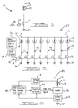
- the PWM circuit 10 includes an incandescent lamp 12 having a filament 14.
- the incandescent lamp 12 has a voltage rating of 12.8v and is conventional and known in the art.
- the filament 14 is connected to a relatively high voltage source 16 such as a battery (not shown) of the motor vehicle having a voltage rating higher than the voltage rating of the incandescent lamp 12.
- the voltage source 16 is 38.4v.
- the PWM circuit 10 also includes a PWM device 18 connected to the filament 14 of the incandescent lamp 12 and to ground 20.
- the PWM device 18 may be a power mosfet or other switching device to provide a pulse width modulated 42v as a source to power the 12.8v incandescent lamp 12.
- the PWM circuit 10 further includes a turn-on amplitude controller 22 electrically connected to the PWM device 18.
- the amplitude controller 22 produces a 100 Hz drive signal with a duty cycle of 12% for the power semiconductor switch of the PWM device 18.
- a duty cycle 24 has a maximum duty cycle of 12.5%, i.e., the incandescent lamp 12 is supplied with 42v at a duty cycle of about 12.5%, more preferably at about 11.8% to 12% to match the light output and colour temperature of the same incandescent lamp operated at 12.8v.
- the 100 Hz would be the lowest repetition rate that would not, cause a perceptible light flickering of the incandescent lamp 12. It should also be appreciated that the selection of the repetition rate will depend on the tradeoffs of such factors as EMI, undesirable audibility from the electrical loads and switching losses in the PWM device 18.
- the range of repetition rate in typical operation is 100 Hz to 40 kHz. Any repetition rate greater than 40 kHz is possible, however, the switching loses may render its application inefficient.
- a pulse width modulation (PWM) system 30 is illustrated for a motor vehicle (not shown).
- the PWM system 30 includes a plurality of the PWM circuits 10 arranged electrically in parallel with each other. In this embodiment, there are eight PWM circuits 10.
- the PWM system 30 includes an oscillator or wave generator 32 and a counter 34 electrically interconnecting the oscillator 32 and the amplitude controller 22.
- the oscillator 32 is a square wave generator for supplying a square wave of, but not limited to, 800 Hz.
- the counter 34 is of an octal type, which produces eight sequential output pulses with the required duty cycle of 12.5%.
- Each of these eight pulses are used to drive a power mosfet in the PWM device 18 of the PWM circuit 10 that turn the incandescent lamp 12 On and Off. It should be appreciated that the amount of power controlled by each power mosfet of the PWM device 18 would depend on the current rating of the mosfet used. It should also be appreciated that, for vehicle lighting applications, each of the PWM circuits 10 would be controlling about 70 watts (which would be sufficient for each filament of a headlamp, which is rated at 55W for the low beam and 65W for the high beam).
- the PWM system 40 includes at least one, preferably a plurality of the PWM circuits 10 arranged electrically in parallel with each other. In this embodiment, only one of the PWM circuits 10 is illustrated.
- the PWM system 40 replaces the oscillator 32 and counter 34 with an application specific integrated circuit or a microcontroller to be described.
- the PWM system 40 includes a current sensor 42 electrically interconnecting the PWM device 18 and the ground 20.
- the PWM system 40 also includes a voltage sensor 44 electrically interconnecting the filament 14 of the incandescent lamp 12 and the high voltage source 16.
- the PWM system 40 further includes a PWM generator 46 having a variable duty cycle electrically interconnecting the voltage sensor 44 and the current sensor 42.
- the PWM system 40 includes the amplitude controller 22 electrically interconnecting the PWM generator 46, PWM device 18 and the current sensor 42.
- the amplitude controller 22 produces a 100 Hz drive signal with a duty cycle of 12% for the power semiconductor switch of the PWM device 18. It should be appreciated that the theoretical duty cycle is 11.1%, but 12% was chosen to account for losses in the wiring and switching losses in the transistor.
- the PWM system 40 performs a current limiting function during an initial turn On of the incandescent lamp 12 where the inrush current could be as high as six times the rated current.
- the peak current is about 26.2 ampere for the first 500 microseconds and the average current for the first 10 milliseconds is about 25 ampere.
- the current decay to the rated current is about 4.2 ampere after 250 milliseconds.
- the PWM system 40 operates the PWM circuit 10 with a constant duty cycle during the turn On phase and operates the PWM device 18 in a linear mode as such that the power and energy supplied to the incandescent lamp 12 is small during the start up phase and gradually increased to the rated value of the incandescent lamp 12 within a period of time, typically 100 to 200 millisecond. It should be appreciated that lamp life degrades in direct relation to how many times the incandescent lamp 12 was turned On which is then attributed to the inrush current.
- the PWM generator 46 modulates the amplitude of the PWM drive signal from the amplitude controller 22 to PWM device 18.
- a PWM drive signal starting with an amplitude of zero and ramping the amplitude to a predetermined value (e.g., 5v or any appropriate value) that is required to fully turn On the PWM device 18 over a time period of 0.1 seconds to 0.3 seconds or longer depending on its application.
- the PWM system 40 performs a current monitoring and current limiting functions. When over current of a predetermined amplitude occurs, the amplitude of the drive signal is reduced by the amplitude controller 22 to zero to turn Off the PWM device 18.
- the PWM system 40 provides a dimming function to the incandescent lamp 12 by decreasing the amplitude of the PWM drive signal by the amplitude controller 22 over a period of time from anywhere between 2 second to 5 second.
- the PWM system 40 performs a light output regulating function, varies lamp output directly with voltage, and varies vehicle system voltage from 12v to 14.6v (or 36v to 45.8v in a 42v system).
- the duty cycle generated by the PWM generator 46 may be varied or changed inversely proportional to the voltage, e.g. at 36v the duty cycle could be 12.5% and at 45.8 volt the duty cycle is changed to 11%. It should be appreciated that, by varying the duty cycle in inverse proportion to the system voltage, constant power and therefore constant light output can be obtained from the incandescent lamp 12, thereby increasing the life of the incandescent lamps 12.
- the present invention is applicable to any lamp circuit where a higher voltage than its rating is applied.
- the present invention can be used for powering 6v incandescent lamps or a 24v truck electrical system can be used to power a 12v incandescent lamp without any lamp burnout.
- the amplitude controller 22 can be applied to current 12v vehicle lighting system to limit inrush current, thereby extending lamp life.
Landscapes
- Circuit Arrangement For Electric Light Sources In General (AREA)
- Lighting Device Outwards From Vehicle And Optical Signal (AREA)
Abstract
Description
Claims (17)
Applications Claiming Priority (2)
| Application Number | Priority Date | Filing Date | Title |
|---|---|---|---|
| US558263 | 1990-07-25 | ||
| US09/558,263 US6307330B1 (en) | 2000-04-25 | 2000-04-25 | System and method for operating incandescent lamps with high voltage source |
Publications (3)
| Publication Number | Publication Date |
|---|---|
| EP1154677A2 true EP1154677A2 (en) | 2001-11-14 |
| EP1154677A3 EP1154677A3 (en) | 2003-10-29 |
| EP1154677B1 EP1154677B1 (en) | 2008-02-27 |
Family
ID=24228842
Family Applications (1)
| Application Number | Title | Priority Date | Filing Date |
|---|---|---|---|
| EP01302906A Expired - Lifetime EP1154677B1 (en) | 2000-04-25 | 2001-03-28 | System and method for operating incandescent lamps with high voltage source |
Country Status (3)
| Country | Link |
|---|---|
| US (1) | US6307330B1 (en) |
| EP (1) | EP1154677B1 (en) |
| DE (1) | DE60132948T2 (en) |
Cited By (2)
| Publication number | Priority date | Publication date | Assignee | Title |
|---|---|---|---|---|
| DE10252623A1 (en) * | 2002-11-11 | 2004-05-27 | Conti Temic Microelectronic Gmbh | Incandescent lamp operating method for motor vehicle, involves generating voltage pulses from operating voltage by pulse width modulation and providing generated pulses to incandescent lamp for power supply |
| DE10334362A1 (en) * | 2003-07-25 | 2005-02-10 | Conti Temic Microelectronic Gmbh | Operation of a filament bulb at a voltage higher than its nominal voltage, e.g. for automotive application, whereby a supply voltage is pulse width modulated at a frequency above the resonant frequency of the bulb filament |
Families Citing this family (18)
| Publication number | Priority date | Publication date | Assignee | Title |
|---|---|---|---|---|
| DE19854416A1 (en) * | 1998-11-25 | 2000-05-31 | Linde Ag | Voltage converter and industrial truck with DC voltage supply |
| JP2002087151A (en) * | 2000-09-19 | 2002-03-26 | Aisin Seiki Co Ltd | Vehicle lamp control device |
| IL138838A0 (en) * | 2000-10-03 | 2001-10-31 | Menachem Hadar | Vehicle brake light system and method |
| WO2002097548A1 (en) * | 2001-05-30 | 2002-12-05 | Accu-Sort Systems, Inc. | Amplitude control of gas discharge lamps |
| US6489729B1 (en) * | 2001-06-11 | 2002-12-03 | Koninklijke Philips Electronics N.V. | Auxiliary lighting system for high intensity discharge lamp |
| DE10226793A1 (en) * | 2002-06-15 | 2004-01-08 | Philips Intellectual Property & Standards Gmbh | Power supply circuit for automotive lamps |
| US8063575B2 (en) | 2002-07-04 | 2011-11-22 | Tridonic Jennersdorf Gmbh | Current supply for luminescent diodes |
| US7372210B2 (en) * | 2003-10-01 | 2008-05-13 | Snap-On Incorporated | Method and apparatus for lamp heat control |
| US20050174788A1 (en) * | 2004-01-30 | 2005-08-11 | Niagara Precision, Inc. | High intensity lamp system for a motorcycle |
| DE102006055610A1 (en) * | 2006-11-24 | 2008-05-29 | Hella Kgaa Hueck & Co. | Method for the pulsed energization of incandescent lamps in motor vehicles |
| US7540641B2 (en) * | 2007-02-08 | 2009-06-02 | Ford Global Technologies, Llc | Apparatus and method for dimming function to control LED intensity |
| US20080191626A1 (en) * | 2007-02-08 | 2008-08-14 | Ford Global Technologies, Llc | Lighting system |
| US7812647B2 (en) * | 2007-05-21 | 2010-10-12 | Advanced Analogic Technologies, Inc. | MOSFET gate drive with reduced power loss |
| US9885451B2 (en) | 2013-01-28 | 2018-02-06 | Exposure Illumination Architects, Inc. | Systems and methods for an intermediate device structure |
| US9829185B2 (en) | 2013-01-28 | 2017-11-28 | Exposure Illumination Architects, Inc. | Intermediate device structure for illumination poles and a method of use thereof |
| US11071204B2 (en) | 2013-02-20 | 2021-07-20 | Exposure Illumination Architects, Inc. | Parking management system |
| US12232232B2 (en) | 2013-02-20 | 2025-02-18 | Lighting Defense Group, Llc | Environmental hazard risk mitigation system, method and computer program product in urban and suburban environments |
| US11565597B2 (en) | 2013-02-20 | 2023-01-31 | Lighting Defense Group, Llc | Wireless electric vehicle charging managed by a parking manager device |
Family Cites Families (23)
| Publication number | Priority date | Publication date | Assignee | Title |
|---|---|---|---|---|
| US4156166A (en) * | 1976-08-18 | 1979-05-22 | Royal Industries, Inc. | Method and apparatus for saving energy |
| US4237405A (en) * | 1978-03-10 | 1980-12-02 | Lear Siegler, Inc. | Method and apparatus for conserving energy |
| US4309639A (en) | 1979-09-24 | 1982-01-05 | Thrower Jr Herbert T | Light modulator system and method |
| DE3147619A1 (en) * | 1981-12-02 | 1983-06-09 | Blaupunkt-Werke Gmbh, 3200 Hildesheim | Circuit for illuminating an LCD display in motor vehicles |
| US4841198A (en) | 1987-10-19 | 1989-06-20 | Nartron Corporation | Head lamp control method and apparatus, with PWM output regulation |
| DE3800950A1 (en) * | 1988-01-15 | 1989-10-05 | Minox Gmbh | Electrical circuit |
| US4845465A (en) | 1988-01-28 | 1989-07-04 | Navistar International Transportation Corp. | Multiplexed D.C. electrical systems for automotive vehicles |
| US5293077A (en) | 1988-02-29 | 1994-03-08 | Hitachi, Ltd. | Power switching circuit |
| DE3809481A1 (en) * | 1988-03-22 | 1989-10-12 | Philips Patentverwaltung | CIRCUIT ARRANGEMENT FOR GENERATING A PULSE SUPPLY VOLTAGE FOR A CONSUMER FROM A DC VOLTAGE |
| GB2219896A (en) * | 1988-06-14 | 1989-12-20 | Bosch Gmbh Robert | Operating incandescent light bulbs to prevent surge currents |
| US5015918A (en) * | 1988-07-22 | 1991-05-14 | John Copeland | Bicycle single-wire lighting system with steady-flashing-reflector rear warning device |
| US4935641A (en) | 1988-08-02 | 1990-06-19 | Nartron Corporation | Electronic rheostat method and apparatus |
| US4902958A (en) | 1988-11-14 | 1990-02-20 | Progressive Dynamics, Inc. | Incandescent light regulation and intensity controller |
| US5053680A (en) * | 1989-06-07 | 1991-10-01 | U.S. Philips Corporation | Switching device |
| US5343122A (en) * | 1989-07-27 | 1994-08-30 | Ken Hayashibara | Luminaire using incandescent lamp as luminous source |
| DE69017883T2 (en) | 1990-01-29 | 1995-10-12 | Philips Electronics Nv | Switching arrangement. |
| US5053677A (en) | 1990-05-03 | 1991-10-01 | Navistar International Transportation Corp. | Parking lamp operating system |
| US5373215A (en) * | 1993-07-07 | 1994-12-13 | The United States Of America As Represented By The United States Department Of Energy | Ionization tube simmer current circuit |
| JPH0732941A (en) | 1993-07-15 | 1995-02-03 | Alps Electric Co Ltd | Automotive lighting device protection circuit |
| DE4324331A1 (en) * | 1993-07-20 | 1995-01-26 | Sokolov Vladimir Dipl El Ing | Supply system for feeding electrical bulb having specified rated voltage |
| US5404094A (en) | 1994-03-18 | 1995-04-04 | Holophane Lighting, Inc. | Wide input power supply and method of converting therefor |
| DE19630644C2 (en) * | 1996-07-30 | 2003-04-03 | Eberspaecher J Gmbh & Co | Electric lighting device |
| DE19854416A1 (en) * | 1998-11-25 | 2000-05-31 | Linde Ag | Voltage converter and industrial truck with DC voltage supply |
-
2000
- 2000-04-25 US US09/558,263 patent/US6307330B1/en not_active Expired - Fee Related
-
2001
- 2001-03-28 DE DE60132948T patent/DE60132948T2/en not_active Expired - Lifetime
- 2001-03-28 EP EP01302906A patent/EP1154677B1/en not_active Expired - Lifetime
Cited By (3)
| Publication number | Priority date | Publication date | Assignee | Title |
|---|---|---|---|---|
| DE10252623A1 (en) * | 2002-11-11 | 2004-05-27 | Conti Temic Microelectronic Gmbh | Incandescent lamp operating method for motor vehicle, involves generating voltage pulses from operating voltage by pulse width modulation and providing generated pulses to incandescent lamp for power supply |
| DE10334362A1 (en) * | 2003-07-25 | 2005-02-10 | Conti Temic Microelectronic Gmbh | Operation of a filament bulb at a voltage higher than its nominal voltage, e.g. for automotive application, whereby a supply voltage is pulse width modulated at a frequency above the resonant frequency of the bulb filament |
| DE10334362B4 (en) * | 2003-07-25 | 2016-06-02 | Conti Temic Microelectronic Gmbh | Method and control device for operating an incandescent lamp, motor vehicle with such a drive device and method for determining the natural resonant frequency of a filament |
Also Published As
| Publication number | Publication date |
|---|---|
| US6307330B1 (en) | 2001-10-23 |
| EP1154677B1 (en) | 2008-02-27 |
| DE60132948D1 (en) | 2008-04-10 |
| EP1154677A3 (en) | 2003-10-29 |
| DE60132948T2 (en) | 2009-03-12 |
Similar Documents
| Publication | Publication Date | Title |
|---|---|---|
| EP1154677B1 (en) | System and method for operating incandescent lamps with high voltage source | |
| EP2885575B1 (en) | Method and apparatus to control light intensity as voltage fluctuates | |
| EP1608206B1 (en) | Led driving device with variable light intensity | |
| US20060238139A1 (en) | High efficiency off-line linear power supply | |
| US6455951B1 (en) | Auto charger for system including a high voltage supply and a low voltage supply | |
| CA2143371A1 (en) | Wide input power supply | |
| JPS62259391A (en) | Circuit arrangement for high voltage discharge lamp operation | |
| JP4379829B1 (en) | Light source driving method and light source driving device | |
| US6919695B2 (en) | Overvoltage protection for hid lamp ballast | |
| JP2001069667A (en) | Vehicle lamp lighting drive device | |
| US6548993B1 (en) | Power supply module having internal energy storage circuit for stable oscillation | |
| JP4116327B2 (en) | Lamp lighting circuit and lamp lighting method | |
| US6677710B2 (en) | DC output regulator using dual pulse modulation | |
| JP5562081B2 (en) | LED dimming method and dimming device | |
| US7071627B2 (en) | Lighting system and method | |
| JP3705490B2 (en) | Load drive device | |
| US8111002B2 (en) | Device and method for operating a high-pressure discharge lamp | |
| US20020117898A1 (en) | Power-supply device for electrical components which are installed in a motor vehicle | |
| KR100999455B1 (en) | Alternator Control Circuit | |
| WO2013035177A1 (en) | Dimming method and dimming device for led | |
| EP1016329A1 (en) | Group dimming system for gas discharge lamps | |
| KR100304585B1 (en) | Power factor correcting apparatus of inverter | |
| US5907219A (en) | Motor vehicle circuitry including a pre-driver control | |
| JP2004165012A (en) | Lamp driving device and lamp driving method | |
| GB2380336A (en) | Power supply circuit for vehicle lamp |
Legal Events
| Date | Code | Title | Description |
|---|---|---|---|
| PUAI | Public reference made under article 153(3) epc to a published international application that has entered the european phase |
Free format text: ORIGINAL CODE: 0009012 |
|
| AK | Designated contracting states |
Kind code of ref document: A2 Designated state(s): AT BE CH CY DE DK ES FI FR GB GR IE IT LI LU MC NL PT SE TR |
|
| AX | Request for extension of the european patent |
Free format text: AL;LT;LV;MK;RO;SI |
|
| PUAL | Search report despatched |
Free format text: ORIGINAL CODE: 0009013 |
|
| AK | Designated contracting states |
Kind code of ref document: A3 Designated state(s): AT BE CH CY DE DK ES FI FR GB GR IE IT LI LU MC NL PT SE TR |
|
| AX | Request for extension of the european patent |
Extension state: AL LT LV MK RO SI |
|
| 17P | Request for examination filed |
Effective date: 20040312 |
|
| AKX | Designation fees paid |
Designated state(s): DE GB SE |
|
| GRAP | Despatch of communication of intention to grant a patent |
Free format text: ORIGINAL CODE: EPIDOSNIGR1 |
|
| GRAS | Grant fee paid |
Free format text: ORIGINAL CODE: EPIDOSNIGR3 |
|
| GRAA | (expected) grant |
Free format text: ORIGINAL CODE: 0009210 |
|
| RAP1 | Party data changed (applicant data changed or rights of an application transferred) |
Owner name: FORD GLOBAL TECHNOLOGIES, LLC |
|
| AK | Designated contracting states |
Kind code of ref document: B1 Designated state(s): DE GB SE |
|
| REG | Reference to a national code |
Ref country code: GB Ref legal event code: FG4D |
|
| REF | Corresponds to: |
Ref document number: 60132948 Country of ref document: DE Date of ref document: 20080410 Kind code of ref document: P |
|
| REG | Reference to a national code |
Ref country code: SE Ref legal event code: TRGR |
|
| PLBE | No opposition filed within time limit |
Free format text: ORIGINAL CODE: 0009261 |
|
| STAA | Information on the status of an ep patent application or granted ep patent |
Free format text: STATUS: NO OPPOSITION FILED WITHIN TIME LIMIT |
|
| 26N | No opposition filed |
Effective date: 20081128 |
|
| PGFP | Annual fee paid to national office [announced via postgrant information from national office to epo] |
Ref country code: GB Payment date: 20100208 Year of fee payment: 10 |
|
| GBPC | Gb: european patent ceased through non-payment of renewal fee |
Effective date: 20110328 |
|
| PG25 | Lapsed in a contracting state [announced via postgrant information from national office to epo] |
Ref country code: GB Free format text: LAPSE BECAUSE OF NON-PAYMENT OF DUE FEES Effective date: 20110328 |
|
| REG | Reference to a national code |
Ref country code: DE Ref legal event code: R082 Ref document number: 60132948 Country of ref document: DE Representative=s name: DOERFLER, THOMAS, DR.-ING., DE |
|
| PGFP | Annual fee paid to national office [announced via postgrant information from national office to epo] |
Ref country code: SE Payment date: 20170307 Year of fee payment: 17 |
|
| PGFP | Annual fee paid to national office [announced via postgrant information from national office to epo] |
Ref country code: DE Payment date: 20170331 Year of fee payment: 17 |
|
| REG | Reference to a national code |
Ref country code: DE Ref legal event code: R119 Ref document number: 60132948 Country of ref document: DE |
|
| PG25 | Lapsed in a contracting state [announced via postgrant information from national office to epo] |
Ref country code: SE Free format text: LAPSE BECAUSE OF NON-PAYMENT OF DUE FEES Effective date: 20180329 |
|
| PG25 | Lapsed in a contracting state [announced via postgrant information from national office to epo] |
Ref country code: DE Free format text: LAPSE BECAUSE OF NON-PAYMENT OF DUE FEES Effective date: 20181002 |