EP1154632A2 - Method, system, program and data structure for generating raster objects - Google Patents
Method, system, program and data structure for generating raster objects Download PDFInfo
- Publication number
- EP1154632A2 EP1154632A2 EP01000123A EP01000123A EP1154632A2 EP 1154632 A2 EP1154632 A2 EP 1154632A2 EP 01000123 A EP01000123 A EP 01000123A EP 01000123 A EP01000123 A EP 01000123A EP 1154632 A2 EP1154632 A2 EP 1154632A2
- Authority
- EP
- European Patent Office
- Prior art keywords
- line work
- contone
- pixel
- objects
- data
- Prior art date
- Legal status (The legal status is an assumption and is not a legal conclusion. Google has not performed a legal analysis and makes no representation as to the accuracy of the status listed.)
- Withdrawn
Links
Images

Classifications
-
- G—PHYSICS
- G06—COMPUTING OR CALCULATING; COUNTING
- G06F—ELECTRIC DIGITAL DATA PROCESSING
- G06F3/00—Input arrangements for transferring data to be processed into a form capable of being handled by the computer; Output arrangements for transferring data from processing unit to output unit, e.g. interface arrangements
- G06F3/12—Digital output to print unit, e.g. line printer, chain printer
-
- H—ELECTRICITY
- H04—ELECTRIC COMMUNICATION TECHNIQUE
- H04N—PICTORIAL COMMUNICATION, e.g. TELEVISION
- H04N1/00—Scanning, transmission or reproduction of documents or the like, e.g. facsimile transmission; Details thereof
- H04N1/387—Composing, repositioning or otherwise geometrically modifying originals
- H04N1/3871—Composing, repositioning or otherwise geometrically modifying originals the composed originals being of different kinds, e.g. low- and high-resolution originals
-
- G—PHYSICS
- G06—COMPUTING OR CALCULATING; COUNTING
- G06K—GRAPHICAL DATA READING; PRESENTATION OF DATA; RECORD CARRIERS; HANDLING RECORD CARRIERS
- G06K15/00—Arrangements for producing a permanent visual presentation of the output data, e.g. computer output printers
- G06K15/02—Arrangements for producing a permanent visual presentation of the output data, e.g. computer output printers using printers
-
- G—PHYSICS
- G06—COMPUTING OR CALCULATING; COUNTING
- G06K—GRAPHICAL DATA READING; PRESENTATION OF DATA; RECORD CARRIERS; HANDLING RECORD CARRIERS
- G06K15/00—Arrangements for producing a permanent visual presentation of the output data, e.g. computer output printers
- G06K15/02—Arrangements for producing a permanent visual presentation of the output data, e.g. computer output printers using printers
- G06K15/18—Conditioning data for presenting it to the physical printing elements
- G06K15/1848—Generation of the printable image
- G06K15/1852—Generation of the printable image involving combining data of different types
- G06K15/1855—Combining raster data and graphic primitives
Definitions
- the present invention relates to a method, system, program, and data structures for generating raster objects that are used in further processing to generate the output raster data used to control a device to generate output.
- a print engine processor converts the image in a page description language or vector graphics format to a bit mapped image indicating a value to print at each pixel of the image.
- the bit mapped image is sent to the printer to cause the print heads to print the specified colour value at the pixel according to the information in the bit map. If a printer has multiple print heads, such as a print head for different colours, then bit maps are generated for each print head.
- the print heads overlay the images defined by their respective bit maps onto the print medium.
- the raster image processor performs numerous transformations on a print image, which may include different types of data, such as line art, e.g., text and graphics, and continuous tone ("contone"), e.g., images.
- the raster image processor usually performs operations such as data compression, colour space conversion, and halftoning when generating the raster bit map to print. After dissecting a print image into different components, such as colour components, text art, contone, images, etc., the raster image processor must then merge the different elements together so that the original image, previously split into different components, is reconstructed for the colour plane process.
- a plurality of input contone and line work objects are received containing contone or line work data for at least one pixel on a sheet.
- For each input contone object at least one output contone object is generated including colour data for each pixel in the input contone object.
- For each input line work object, at least one output line work object is generated including colour data for each pixel in the input print data object.
- Control data is generated for each pixel indicating whether to select data from the output line work object or output contone object for the pixel, wherein the control data is used by logic to select colour data from the output line work object or output contone object for pixel data to send to an output device to render the pixel data.
- one intermediary line work object including colour data for each pixel in the input line work object is generated for each input line work object.
- the output line work object is generated from one intermediary line work object.
- One intermediary contone object including colour data for each pixel in the input contone object is generated for each input contone object.
- the output contone object is generated from one intermediary contone object.
- a determination is made as to whether there are more than a maximum number of intermediary line work objects that intersect one scan line. If so, multiple intermediary line work objects are merged into one merged output line work object if there are more than the maximum number of intermediary line work objects intersecting the scan line.
- One output line work object is generated for the merged intermediary line work object such that the generated output line work objects that intersect a scan line are less than the maximum number.
- Preferred embodiments provide an algorithm and data structures for a raster image processor to use to generate a set of raster objects from independent displayable objects (IDOs) that may be further processed by another logic component, such as a processor or hardware card.
- IDOs independent displayable objects
- These set of raster objects generated by the raster image processor include colour data from line work or contone objects and control bits indicating which raster object to use to select the colour data for a pixel.
- IDOs independent displayable objects
- These set of raster objects generated by the raster image processor include colour data from line work or contone objects and control bits indicating which raster object to use to select the colour data for a pixel.
- This relief provided to the raster image processor improves the performance of the raster generation process and ultimately improves print speed by allowing final output raster data to be fed at a faster rate to the printer.
- the method, system, computer program product and computer readable medium may contain the following preferable features.
- They may generate for each input contone and line work objects one output contone and line work object for each colour component of the colour data.
- the method, system, computer program product and computer medium may include the following features: generating from each input line work object one intermediary line work object including colour data for each pixel in the input line work object, wherein the output line work object is generated from one intermediary line work object; generating from each input contone object one intermediary contone object including colour data for each pixel in the input contone object, wherein the output contone object is generated from one intermediary contone object; determining whether there are more than a maximum number of intermediary line work objects that intersect one scan line; and merging multiple intermediary line work objects into one merged output line work object if there are more than the maximum number of intermediary line work objects intersecting the scan line, wherein one output line work object is generated for the merged intermediary line work object such that the generated output line work objects that intersect a scan line are less than the maximum number.
- Merging the intermediary line work objects may comprise: determining regions comprising one or more scan lines intersected by a set of one or more intermediary line work objects, wherein there is a separate region for each set of scan lines intersected by a unique set of intermediary line work objects; and determining for each region the set of intermediary line work objects that intersect the region, wherein the output line work object objects are generated for each region and one merged output line work objects is generated for each region that has more than the maximum number of intermediary line work objects that intersect the region.
- Each intermediary line work object may have an associated priority value, wherein colour data of one intermediary line work object is to be displayed over colour data from intermediary line work objects having a lower associated priority, wherein the code is further capable of causing the processor to perform: selecting at least two intermediary line work objects to merge into one merged output line work object for the region, wherein there is no intermediary line work object having a priority between the priorities associated with the selected line work object.
- the method, system, computer program product and computer medium may include the following features: associating a priority value with each intermediary line work and contone object has an associated priority value; defining at least one set of one or more input line work objects that provide pixel data for a same set of one or more scan lines: selecting, for each defined set of line work objects, a highest priority input line work object in one set of input line work objects; and generating, for each defined set of line work objects, colour data for each pixel in the output line work object from non-transparent colour data supplied for the pixel from the selected input line work object and setting the control data for the pixel to use the colour data in the output line work object if there is no input contone object including non-transparent colour data for the pixel having higher priority than the selected input line work object.
- the control data for the pixel in the output line work object for the selected input line work object may be set to use non-transparent colour data in the output contone object for the pixel if the input contone object providing the non-transparent colour data has a higher priority than the selected input line work object.
- the control data for the pixel in the output line work object may be set to transparent if the input line work object for the output line work object has transparent colour data for the pixel and there is no input contone object with a higher priority than the selected input line work object providing non-transparent colour data for the pixel, wherein a control data setting of transparent indicates that a next lower priority output line work object is considered to determine the colour data for the pixel or that no colour data is provided for the pixel.
- a header object may be generated for each output line work object and output contone object including information identifying a location of the corresponding output line work or contone object in memory.
- a linked list of pointers to the header objects may be generated corresponding to output line work and contone objects, wherein the list of pointers is ordered based on a priority associated with the input line work and contone objects used to generate the output line work and contone objects.
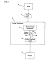
- FIG. 1 illustrates a printing environment in which described embodiments are implemented.
- a host computer 2 generates a print job 4 that may include image (contone) and line work (text) components.
- the host 2 transmits the print job 4 to a printer controller 6 over a cable or network transmission line.
- the printer controller 6 may comprise a standalone processor or computer, such as the IBM RS/6000 (RS/6000 is a registered trademark of International Business Machines Corporation.) processor.
- the printer controller 6 includes a raster image processor 8, that is preferably implemented in the RS/6000 main processor and accompanying firmware.
- the raster image processor 8 generates raster objects 10a, b, c, d including the raster data.
- Each raster object 10a, b, c, d includes pixel information for one colour component of the imaging system 12. For instance, if the imaging system 12 prints Cyan (C), Magenta (M), Yellow (Y) and black (K), then there would be one raster object for each colour component for a scan line to print. Further, there may be separate raster objects 10a, b, c, d for line art and contone (images), thus providing 8 separate raster objects for each colour component of a scan line for the line art and contone components of the line.
- the printer controller 6 and imaging system 12 components may be implemented in the same large scale printer, such as the International Business Machines (IBM) Corporation's Infoprint colour printers (Infoprint is a registered trademark of International Business Machines Corporation.) or with a separate server and standalone printer communicating over a network or attached directly using a serial or parallel port.
- IBM International Business Machines
- Infoprint is a registered trademark of International Business Machines Corporation.
- Described embodiments include a colour interface card (CIC) 14 that is preferably implemented on a hardware card, such as a PCI card using Field Programmable Gate Array (FPGA) logic.
- the CIC card 14 may be inserted in a PCI slot of the backplane of the printer controller 6.
- the CIC card 14 performs further processing of the raster objects 10 before they are sent to the imaging system 12 for printing.
- one CIC card 14 is capable of producing print data for two of the colour planes. In such case, two CIC cards are needed to generate the final raster for the output device for all four colour planes. In duplex implementations where the printer prints on both sides of a sheet concurrently, four CIC cards would be used, two for each side of the sheet to concurrently generate raster data for the print heads printing to both sides.
- Described embodiments provide an algorithm and data structure for the raster image processor 8 to use to generate separate line work and contone objects that are sent to the CIC card 14 to combine and produce the final print output.
- the raster image processor 8 encodes the line work and contone objects with header information that enables the CIC card 14 logic to combine multiple line work and contone objects per scan line into final print output. In this way, many of the raster processing operations can be off-loaded to a separate hardware card, thereby relieving the raster image processor 8 of many of the processor intensive raster operations. This in turn substantially increase the ultimate printer speed and performance because the final raster output data used by the printer (or other output device) is generated faster by offloading many of the raster processing operations to dedicated hardware logic implemented in the CIC card 14.
- the CIC card 14 includes hardware logic to handle up to four line work and four contone objects per scan line per colour, totalling 16 line work and 16 contone objects per scan line. For this reason, if the raster image processor 8 receives input print data objects including more than four contone or line work objects per scan line, then the raster image processor 8 must merge certain objects to conform to the CIC card 14 hardware limitations. If the CIC card 14 was capable of handling more or less line work or contone objects per scan line, i.e., n objects, then the raster image processor 8 would have to merge input print data objects to ensure that there are no more than n line work or n contone objects per scan line.
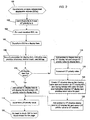
- FIGs. 2, 5a, b, and 6 illustrate logic executed by the raster image processor 8 to generate raster objects 10a, b, c, d that may later be used by the CIC card 14 in accordance with the described embodiments.
- FIG. 2 illustrates logic executed by the raster image processor 8 to transform input independent displayable objects (IDOs), comprising text, bi-level, vector graphics, page description commands or any other data format that may be generated by an application program, into an intermediary object referred to as a display item that includes the print information from the input print data object.
- IDOs input independent displayable objects
- Print information may comprise a bitmap indicating colour values for particular pixels in a sheet or page description language commands instructing the placement of colour values at particular locations on the sheet.
- Control begins at block 100 with the raster image processor 8 receiving one or more independent displayable objects (IDOs).
- IDOs may comprise text, images, graphics, compressed images, non-compressed images, rectangles, bar codes, page description language commands, etc.
- the raster image processor 8 sets a line work (LW) and contone (CT) priority variables to zero.
- LW line work
- CT contone priority variables
- a display item includes a bit map of data indicating what to display for pixels on one or more scan lines.
- the raster image processor 8 would further generate (at block 108) a set of properties for each line work and contone display item, indicating the display item size, position information for the colour data on the sheet, and a control mask.
- the control mask indicates whether colour data for a particular pixel in the display item should be displayed (is non-transparent) or not displayed (is transparent).
- Display item types include solid rectangles, bilevel bitmaps, JPEG (Joint Photographics Expert Group) images, etc.
- a solid rectangle display item would include CMYK colour data, height and width data and position data on the sheet for the solid shape.
- a bilevel display item is generated for independent displayable objects (IDO) comprising text, bilevel images or bar code that has only a single colour.
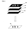
- the bilevel display item includes four one byte colour objects for the four colour planes CMYK and a line work mask. The combination of the colours for each of the four colour planes specified in the CMYK colour objects together define the colour of the bi-level display item.
- the line work mask comprises a bit value for each pixel of the bi-level image area. An "on" value indicates that the bi-level image provides colour for that pixel corresponding to the "on" value (non-transparent data). An “off” mask value indicates that the colour data is not to be used for the pixel (transparent).
- Line work objects 152, 154, 156, and 158 each provide a one byte colour value for one of C, M, Y and K and a line work mask 150.
- the white part of the line work mask 150 represents the non-transparent pixels for which the colour defined by the CMYK objects 152-158 is used and the black areas represent the transparent portions for which the colour data is not used. Thus, the letters appear through the non-transparent pixels indicated in the control mask.
- a JPEG display item is used to define a JPEG compressed continuous tone (contone) image.
- the JPEG display item would include a JPEG continuous tone compressed version of the 32-bit colour values for the picture.
- the amount of loss is controlled by the application (generator of the IDO inputted to the system).
- the raster image processor 8 would produce different line work and contone display items for the different types of independent displayable objects received in an input data stream.
- the raster image processor 8 adds (at block 112) a pointer to the display item to a line work (LW) display list and assigns the current line work (LW) priority value to the display item entry in the display list.
- the line work (LW) priority value is incremented (at block 114).
- the pointer to the display item is added (at block 116) to the contone (CT) display list and the contone (CT) priority value is assigned to the display item entry in the CT display list.
- the contone (CT) priority value is then incremented (at block 118).
- the raster image processor then creates (at block 120) a contone (CT) shadow display item having the same size and location as the contone (CT) display item, and having a bitmap including, for each pixel in the contone (CT) display item, a value indicating whether the contone (CT) display item provides a colour value for the pixel.
- a pointer to the contone (CT) shadow display item is then added (at block 122) to the line work display list and the contone (CT) shadow display item is assigned the priority value of the line work priority variable.
- Control then transfers to block 114.
- the line work (LW) display list maintains information on all line work and contone objects that provide pixel data for a sheet and the relative priority of the provided pixel data.
- This contone (CT) shadow object is used when determining the value to set for the line work control (LWC) bits in the line work object, i.e., whether the data for the pixel should come from one contone object or line work object.
- This process from blocks 106 to 122 occurs for each independent display object (IDO) received for a sheet.
- the end result of the logic of FIG. 2 is line work and contone display lists having pointers to display items having a priority value indicating the order in which the independent display objects were received.
- the raster image processor 8 receives independent display objects (IDOs) according to the priority in which they are to be displayed, such that a later received IDO has priority over any overlapping portions with an earlier received IDO.
- the contone (CT) and line work (LW) priority values assigned to the display items in the display lists indicate the priority in which the print data for the contone and line work display items are to be displayed with respect to other contone and line work display items.
- the line work (LW) display list further indicates (through the use of the contone (CT) shadow display items) whether contone display items also provide data, and a priority of such contone data provided by the contone (CT) display item.
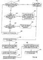
- FIGs. 5a, b illustrate logic executed by the raster image processor 8 to merge contone and line work display item data in a manner that ensures that the number of objects intersecting a scan line does not exceed the maximum that may be handled by the CIC card 14 hardware logic.
- the logic of FIGs. 5a, b provides logic for encoding each pixel represented in the line work object with two line work control (LWC) bits indicating select line work, select contone or transparent.
- LWC line work control
- a select line work value instructs the CIC card 14 logic to use the data provided in the current line work object for the pixel.
- a select contone instructs the CIC card logic 14 to use the data indicated in the highest priority contone object for the pixel.
- a transparent value indicates to consider the next highest priority line work object for the pixel.
- a scan region defines one or more scan lines that encompasses one or more objects. Scan regions are created by processing each scan line. Every time a new object boundary, start or end, appears on a scan line, then the current scan region is divided into two scan regions -- the scan region before the scan line and the one following. The initial scan region begins at the first scan line on a sheet. When the boundary of the first object or a new object is reached, then this initial scan region is divided into one region prior to the boundary and a second region following the boundary, which may then be subdivided further as further start and end boundaries are reached.
- the raster image processor 8 would then include with each defined scan region a list of pointers to the display items that intersect that scan region.
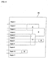
- FIG. 4 illustrates a sheet 250 including (line work or contone) objects A, B, C, D, and E.
- the objects are represented on the sheet 250 according to the X, Y coordinate position.
- Each scan region is defined as having a start scan line and an end scan line.
- the start and end scan lines are positioned where a display item starts or where a display item ends.
- the start and end of a scan region are limited to a fixed set of positions within the sheet such that a scan region contains a minimum number of scan lines. New regions are only created when the start or end of an item falls further outside the minimum scan region boundaries. In this way, each scan region is assured to include a minimum number of scan lines in order to reduce the number of scan regions, and hence, objects created.
- Each object requires processor overhead to generate the header information and to separately process in the CIC card 14.
- performance is improved to the extent the scan line size of a scan region and raster object is increased. This scan region minimum line requirement avoids producing very small scan regions, which degrades performance.
- FIGs. 5a, b illustrate logic implemented in the raster image processor 8 to create the raster objects 10a, b, c, d for each colour plane.
- CT contone
- LW line work
- the raster image processor uses the mask data and other generated data to set two line work control (LWC) bits in the output line work raster object 10a, b, c, d instructing the CIC card 14 whether to use the current line work raster object, use the highest priority contone object or consider the line work object having the next highest priority for a particular pixel.
- LWC line work control
- the process to generate the final contone and line work raster objects 10a, b, c, d used by the CIC card 14 begins at block 300 after generating all the contone and line work scan regions.
- the raster image processor 8 performs a loop of operations 306 to 336 for each scan region i on the sheet to generate the colour data and line work control (LWC) bits for the line work object and the colour data for the contone objects.
- LWC line work control
- the raster image processor 8 sorts all the line work (LW) objects in a scan region i by their priority (assigned at block 112 in FIG. 2).
- the raster image processor 8 then groups (at block 306) the display items into one to four groups.
- each group would have display items of contiguous priority as determined by the sort.
- display items may be assigned into groups based on factors other than contiguous priority, such as the relatedness of the type of data in the display item, e.g., group all display items having data in a certain compression format, certain colour data format, etc. Further, it is possible that display items having non-contiguous priority could be assigned to the same group.
- Each group is then assigned to one of the proxy objects created for a scan region in the raster image processor 8 memory.
- Each proxy object would include pixel information for each pixel in scan region i .
- a line work proxy object is a placeholder into which eight bits of colour data for one colour plane and two bits of line work control (LWC) are encoded for each pixel in scan region i .
- the proxy object is created as part of the process of generating the final line work raster objects 10a, b, c, d capable of being processed by the CIC card 14.
- the raster image processor 8 performs a loop for each proxy object in the scan region i. For each proxy object and for each pixel j in the line work proxy object, the raster image processor performs blocks 310 to 328. At block 312 the raster image processor 8 considers the line work (LW) display item in the proxy object that has the highest priority. If (at block 314), the considered LW display item is a contone shadow display item indicating contone (CT) data for pixel j , then that contone colour value in the contone display item represented by the contone (CT) shadow object should ultimately be selected for the final print output selected by the CIC card 14.
- CT contone
- the raster image processor sets (at block 316) the line work control (LWC) bits to select contone (CT), to cause the CIC card 14 to later select the highest priority non-transparent contone colour value for each pixel j in each colour plane.
- LWC line work control
- the raster image processor determines (at block 318) whether the line work display item being considered has a non-transparent colour value for pixel j . This can be determined from the control mask which has an "on" value for a pixel when there is non-transparent data and an "off" value when the colour data provided is transparent, not to be used.
- the raster image processor 8 sets (at block 320) the eight bit colour data for the colour plane to the value in the line work display item for pixel j in the colour plane (CMYK) and sets the two line work control (LWC) bits to use line work (LW), instructing the CIC card 14 to use the line work data for pixel j .
- the raster image processor 8 determines (at block 322) whether are further display items assigned to the proxy object not yet considered. If not, then the raster image processor 8 sets (at block 324) the line work control (LWC) bits for each colour plane for pixel j to transparent. Otherwise, if (at block 322) there are further display items not yet considered for the proxy object, then the raster image processor 8 considers (at block 326) the next highest priority display item (which can be either a line work or a contone shadow item) and returns to block 314 to use the line work control (LWC) display item being considered to determine data for pixel j in the proxy object for each colour plane.
- the next highest priority display item which can be either a line work or a contone shadow item
- control After setting the value for pixel j for each colour plane of the merged proxy objects at blocks 316, 320 or 324, control proceeds to block 328 to continue the loop for the next ( j + 1)th pixel. After encoding colour data and line work control (LWC) bits for all the pixel data in the current proxy objects for each colour plane, the priority of the merged proxy object is set (at block 330) to the highest priority of the display items assigned to the proxy object. At block 332, control then returns to block 308 to consider the next proxy object, and all line work display items assigned thereto, in the scan region i .
- LWC line work control
- the raster image processor 8 further maintains an X-Y list comprising a linked list of pointers to proxy objects in the order in which they provide pixel data for the sheet.
- the raster image processor 8 sorts (at block 334) the proxy objects for the scan region according to their priority, from low to high.
- a pointer is then added (at block 336) in the X-Y list to each proxy object in the scan region according to the sort order.
- the entries or pointers in the X-Y list are linked such that each entry in the list has a pointer to a proxy object and a pointer to the proxy object added subsequently in the list. Control then returns to block 304 to consider the next ( i + 1)th scan region.
- the raster image processor 8 will have to merge contone (CT) display items in contone (CT) to reduce the number of contone (CT) display items to four.
- CT contone
- This merging process would have to consider whether the pixels in the highest priority contone (CT) display item are transparent and whether data from a lower priority contone (CT) display item should be used in the merged contone (CT) proxy object.
- there are no control bits in the contone objects such as the line work control (LWC) bits, as decisions on whether to use contone or line work data are made with the line work control (LWC) bits in the line work raster object 10a, b, c, d.
- LWC line work control
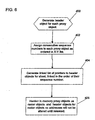
- the raster image processor 8 After generating the colour data for the line work (LW) and contone (CT) proxy objects, the raster image processor 8 would then execute the logic of FIG. 6, beginning at block 400, to generate header information for the proxy object. Below are the fields in the header object the raster image processor 8 would generate for each colour plane (CMYK) of each proxy object. At this point in time, the line work (LW) and contone (CT) proxy objects become raster objects 10a, b, c, d that the CIC card 14 would access.
- the raster image processor 8 further generates (at block 402) sequence numbers for each proxy object according to their order in the X-Y list, i.e., starting from zero at the top of the linked list and numbering consecutively to the bottom of the X-Y linked list.
- the raster image processor 8 then generates (at block 404) a linked list of pointers to the headers according to the sequence number of the corresponding raster object.
- the raster image processor 406 then hardens in memory the proxy objects as raster objects and the header objects thereof so that the raster object and header addresses will not be overwritten or altered in memory by the operating system before they are accessed and then released by the CIC card 14.
- the CIC card 14 hardware may then use the generated raster objects 10a, b, c, d in memory to generate final raster output for an output device, such as a printer, as described in the related and copending patent applications entitled, "Method, System, and Logic For Selecting Line Work And Control Data For a Pixel From Multiple Objects Of Line Work Data Provided For The Pixel", having attorney docket no. BLD9-2000-0015US1.
- the described embodiments have the raster image processor 8 convert input independent displayable objects (IDOs) into display items and then into multiple raster objects which may then be provided to a hardware card, e.g., the CIC card 14, to further process to generate the final print output.
- IDOs input independent displayable objects
- the CIC card 14 e.g., the CIC card 14
- Described embodiments substantially improve the performance of the raster image processor 8 in generating raster data because in the described embodiments the raster image processor 8 only performs those raster steps needed to generate separate line work and contone objects that are further processed, i.e., decompressed, merged and screened, by hardware logic, thus offloading many of the highly processor intensive operations to dedicated hardware logic which can often perform such operations faster than the software or program of the raster image processor 8. Further by having two processors perform raster operations performed in the prior art by a single raster image processor, performance is substantially improved. Thus, described embodiments provide an improved way for allocating particular raster operations to the raster image processor 8 and to another processing unit, such as the CIC card 14 in order to improve the speed and performance of raster image processing.
- the described embodiments may be implemented as a method, apparatus or information bearing media using standard programming and/or engineering techniques to produce software, firmware, hardware, or any combination thereof.
- the programs defining the functions of the described embodiment can be delivered to a computer via a variety of information bearing media, which include, but are not limited to, computer-readable devices, carriers, or media, such as a magnetic storage media, "floppy disk,” CD-ROM, a file server providing access to the programs via a network transmission line, wireless transmission media, signals propagating through space, radio waves, infrared signals, etc.
- information bearing media when carrying computer-readable instructions that direct the functions of the present invention, represent alternative embodiments of the present invention.
- the raster objects had specific information, such as the object type, sequence number, etc., used to determine whether objects were received in the correct order.
- further or modified information may be included in the raster objects to ensure that raster objects are processed in the correct order. Further there may be different or additional object types other than those discussed herein.
- the CIC card that processes the generated raster objects comprises hardware logic.
- an additional processor may be used to perform the further processing of the raster objects generated in accordance with the described embodiments.
- the raster objects are generated for a printer to use to control printer operations.
- the raster objects may provide colour data for another device, such as a computer graphics card or display engine, to use when generating output display data.
- the CIC card may be implemented in hardware other than a PCI card on the printer controller backplane. Still further, operations described as performed in the raster image processor may be moved to the CIC card or alternative raster logic.
- FIGs. 2, 5a, b and 7 described raster operations as occurring in a particular order. However, in alternative embodiments the raster operations may be performed in a different order, and steps may be modified, added or removed. Still further, the raster operations may be executed sequentially or certain operations may be executed in parallel to improve performance.
- independent objects become display items.
- items may be grouped in many ways to produce intermediate objects providing the same display presentation characteristics.
- described embodiments disclose a method, system, program, and data structures for generating raster objects.
- a plurality of input contone and line work objects are received containing contone or line work data for at least one pixel on a sheet.
- For each input contone object at least one output contone object is generated including colour data for each pixel in the input contone object.
- For each input line work object at least one output line work object is generated including colour data for each pixel in the input print data object.
- Control data is generated for each pixel indicating whether to select data from the output line work object or output contone object for the pixel, wherein the control data is used by logic to select colour data from the output line work object or output contone object for pixel data to send to an output device to render the pixel data.
- the present invention is typically implemented as a computer program product, comprising a set of program instructions for controlling a computer or similar device. These instructions can be supplied preloaded into a system or recorded on a storage medium such as a CD-ROM, or made available for downloading over a network such as the Internet or a mobile telephone network.
Landscapes
- Engineering & Computer Science (AREA)
- Theoretical Computer Science (AREA)
- General Engineering & Computer Science (AREA)
- Physics & Mathematics (AREA)
- General Physics & Mathematics (AREA)
- Multimedia (AREA)
- Signal Processing (AREA)
- Human Computer Interaction (AREA)
- Image Processing (AREA)
- Record Information Processing For Printing (AREA)
- Editing Of Facsimile Originals (AREA)
Abstract
Description
- The present invention relates to a method, system, program, and data structures for generating raster objects that are used in further processing to generate the output raster data used to control a device to generate output.
- To print an image, a print engine processor, referred to herein as a raster image processor, converts the image in a page description language or vector graphics format to a bit mapped image indicating a value to print at each pixel of the image. The bit mapped image is sent to the printer to cause the print heads to print the specified colour value at the pixel according to the information in the bit map. If a printer has multiple print heads, such as a print head for different colours, then bit maps are generated for each print head. The print heads overlay the images defined by their respective bit maps onto the print medium.
- To produce the bit maps for the print heads, the raster image processor performs numerous transformations on a print image, which may include different types of data, such as line art, e.g., text and graphics, and continuous tone ("contone"), e.g., images. The raster image processor usually performs operations such as data compression, colour space conversion, and halftoning when generating the raster bit map to print. After dissecting a print image into different components, such as colour components, text art, contone, images, etc., the raster image processor must then merge the different elements together so that the original image, previously split into different components, is reconstructed for the colour plane process.
- As newer printers print at ever higher resolutions and speeds, the amount of data needed to generate the print job correspondingly increases. One of the major challenges in increasing printer speed and improving performance is optimising the time required to rasterize print data, especially the time required by the raster image processor to break an image into different object components and then reassemble, decompress, screen and merge those components into a final bitmap image.
- Thus, there is a need in the art to provide an improved method, system, and program to transform print data, such as text, vector graphics, images and raster data into final rasterized bit maps in a more timely manner to increase printer throughput.
- According to a first aspect of the present invention there is provided a method for generating raster objects as claimed in
claim 1. - According to a second aspect of the present invention there is provided a system for generating raster objects as claimed in
claim 11. - According to a third aspect of the present invention there is provided a computer program product as claimed in claim 21.
- According to a fourth aspect of the present invention there is provided a computer readable medium as claimed in claim 22.
- To overcome the limitations in the prior art described above, described embodiments disclose a method, system, program, and data structures for generating raster objects. A plurality of input contone and line work objects are received containing contone or line work data for at least one pixel on a sheet. For each input contone object, at least one output contone object is generated including colour data for each pixel in the input contone object. For each input line work object, at least one output line work object is generated including colour data for each pixel in the input print data object. Control data is generated for each pixel indicating whether to select data from the output line work object or output contone object for the pixel, wherein the control data is used by logic to select colour data from the output line work object or output contone object for pixel data to send to an output device to render the pixel data.
- In further embodiments, one intermediary line work object including colour data for each pixel in the input line work object is generated for each input line work object. The output line work object is generated from one intermediary line work object. One intermediary contone object including colour data for each pixel in the input contone object is generated for each input contone object. The output contone object is generated from one intermediary contone object. A determination is made as to whether there are more than a maximum number of intermediary line work objects that intersect one scan line. If so, multiple intermediary line work objects are merged into one merged output line work object if there are more than the maximum number of intermediary line work objects intersecting the scan line. One output line work object is generated for the merged intermediary line work object such that the generated output line work objects that intersect a scan line are less than the maximum number.
- Preferred embodiments provide an algorithm and data structures for a raster image processor to use to generate a set of raster objects from independent displayable objects (IDOs) that may be further processed by another logic component, such as a processor or hardware card. These set of raster objects generated by the raster image processor include colour data from line work or contone objects and control bits indicating which raster object to use to select the colour data for a pixel. In this way, many of the merging, screening and decompression operations are offloaded to an external hardware card or processor thereby relieving the raster image processor of substantial processing burdens. This relief provided to the raster image processor improves the performance of the raster generation process and ultimately improves print speed by allowing final output raster data to be fed at a faster rate to the printer.
- The method, system, computer program product and computer readable medium may contain the following preferable features.
- They may generate for each input contone and line work objects one output contone and line work object for each colour component of the colour data.
- The method, system, computer program product and computer medium may include the following features: generating from each input line work object one intermediary line work object including colour data for each pixel in the input line work object, wherein the output line work object is generated from one intermediary line work object; generating from each input contone object one intermediary contone object including colour data for each pixel in the input contone object, wherein the output contone object is generated from one intermediary contone object; determining whether there are more than a maximum number of intermediary line work objects that intersect one scan line; and merging multiple intermediary line work objects into one merged output line work object if there are more than the maximum number of intermediary line work objects intersecting the scan line, wherein one output line work object is generated for the merged intermediary line work object such that the generated output line work objects that intersect a scan line are less than the maximum number.
- Merging the intermediary line work objects may comprise: determining regions comprising one or more scan lines intersected by a set of one or more intermediary line work objects, wherein there is a separate region for each set of scan lines intersected by a unique set of intermediary line work objects; and determining for each region the set of intermediary line work objects that intersect the region, wherein the output line work object objects are generated for each region and one merged output line work objects is generated for each region that has more than the maximum number of intermediary line work objects that intersect the region.
- Each intermediary line work object may have an associated priority value, wherein colour data of one intermediary line work object is to be displayed over colour data from intermediary line work objects having a lower associated priority, wherein the code is further capable of causing the processor to perform: selecting at least two intermediary line work objects to merge into one merged output line work object for the region, wherein there is no intermediary line work object having a priority between the priorities associated with the selected line work object.
- The method, system, computer program product and computer medium may include the following features: associating a priority value with each intermediary line work and contone object has an associated priority value; defining at least one set of one or more input line work objects that provide pixel data for a same set of one or more scan lines: selecting, for each defined set of line work objects, a highest priority input line work object in one set of input line work objects; and generating, for each defined set of line work objects, colour data for each pixel in the output line work object from non-transparent colour data supplied for the pixel from the selected input line work object and setting the control data for the pixel to use the colour data in the output line work object if there is no input contone object including non-transparent colour data for the pixel having higher priority than the selected input line work object.
- The control data for the pixel in the output line work object for the selected input line work object may be set to use non-transparent colour data in the output contone object for the pixel if the input contone object providing the non-transparent colour data has a higher priority than the selected input line work object.
- The control data for the pixel in the output line work object may be set to transparent if the input line work object for the output line work object has transparent colour data for the pixel and there is no input contone object with a higher priority than the selected input line work object providing non-transparent colour data for the pixel, wherein a control data setting of transparent indicates that a next lower priority output line work object is considered to determine the colour data for the pixel or that no colour data is provided for the pixel.
- A header object may be generated for each output line work object and output contone object including information identifying a location of the corresponding output line work or contone object in memory.
A linked list of pointers to the header objects may be generated corresponding to output line work and contone objects, wherein the list of pointers is ordered based on a priority associated with the input line work and contone objects used to generate the output line work and contone objects. - Embodiments of the present invention are now described, by way of examples only, with reference to the accompanying drawings in which:
- FIG. 1 illustrates a printing environment in which embodiments of the present invention are implemented;
- FIGs. 2, 5a, 5b, and 6 illustrate logic to generate line work and raster objects in accordance with embodiments of the present invention;
- FIG. 3 illustrates an example of the component objects of a bi-level display item in accordance with embodiments of the present invention; and
- FIG. 4 illustrates how screen regions are defined for a sheet including multiple line work or contone display items in accordance with embodiments of the present invention.
-
- In the following description, reference is made to the accompanying drawings which form a part hereof and which illustrate several embodiments of the present invention. It is understood that other embodiments may be utilised and structural and operational changes may be made without departing from the scope of the present invention. In the drawings, like reference numbers represent corresponding parts throughout:
- FIG. 1 illustrates a printing environment in which described embodiments are implemented. A
host computer 2 generates aprint job 4 that may include image (contone) and line work (text) components. Thehost 2 transmits theprint job 4 to aprinter controller 6 over a cable or network transmission line. Theprinter controller 6 may comprise a standalone processor or computer, such as the IBM RS/6000 (RS/6000 is a registered trademark of International Business Machines Corporation.) processor. Theprinter controller 6 includes araster image processor 8, that is preferably implemented in the RS/6000 main processor and accompanying firmware. In described embodiments, theraster image processor 8 generatesraster objects 10a, b, c, d including the raster data. Eachraster object 10a, b, c, d includes pixel information for one colour component of theimaging system 12. For instance, if theimaging system 12 prints Cyan (C), Magenta (M), Yellow (Y) and black (K), then there would be one raster object for each colour component for a scan line to print. Further, there may beseparate raster objects 10a, b, c, d for line art and contone (images), thus providing 8 separate raster objects for each colour component of a scan line for the line art and contone components of the line. Theprinter controller 6 andimaging system 12 components may be implemented in the same large scale printer, such as the International Business Machines (IBM) Corporation's Infoprint colour printers (Infoprint is a registered trademark of International Business Machines Corporation.) or with a separate server and standalone printer communicating over a network or attached directly using a serial or parallel port. - Described embodiments include a colour interface card (CIC) 14 that is preferably implemented on a hardware card, such as a PCI card using Field Programmable Gate Array (FPGA) logic. The
CIC card 14 may be inserted in a PCI slot of the backplane of theprinter controller 6. TheCIC card 14 performs further processing of theraster objects 10 before they are sent to theimaging system 12 for printing. - In certain implementations, one
CIC card 14 is capable of producing print data for two of the colour planes. In such case, two CIC cards are needed to generate the final raster for the output device for all four colour planes. In duplex implementations where the printer prints on both sides of a sheet concurrently, four CIC cards would be used, two for each side of the sheet to concurrently generate raster data for the print heads printing to both sides. - Described embodiments provide an algorithm and data structure for the
raster image processor 8 to use to generate separate line work and contone objects that are sent to theCIC card 14 to combine and produce the final print output. Theraster image processor 8 encodes the line work and contone objects with header information that enables theCIC card 14 logic to combine multiple line work and contone objects per scan line into final print output. In this way, many of the raster processing operations can be off-loaded to a separate hardware card, thereby relieving theraster image processor 8 of many of the processor intensive raster operations. This in turn substantially increase the ultimate printer speed and performance because the final raster output data used by the printer (or other output device) is generated faster by offloading many of the raster processing operations to dedicated hardware logic implemented in theCIC card 14. - In described implementations, the
CIC card 14 includes hardware logic to handle up to four line work and four contone objects per scan line per colour, totalling 16 line work and 16 contone objects per scan line. For this reason, if theraster image processor 8 receives input print data objects including more than four contone or line work objects per scan line, then theraster image processor 8 must merge certain objects to conform to theCIC card 14 hardware limitations. If theCIC card 14 was capable of handling more or less line work or contone objects per scan line, i.e., n objects, then theraster image processor 8 would have to merge input print data objects to ensure that there are no more than n line work or n contone objects per scan line. - FIGs. 2, 5a, b, and 6 illustrate logic executed by the
raster image processor 8 to generateraster objects 10a, b, c, d that may later be used by theCIC card 14 in accordance with the described embodiments. FIG. 2 illustrates logic executed by theraster image processor 8 to transform input independent displayable objects (IDOs), comprising text, bi-level, vector graphics, page description commands or any other data format that may be generated by an application program, into an intermediary object referred to as a display item that includes the print information from the input print data object. Print information may comprise a bitmap indicating colour values for particular pixels in a sheet or page description language commands instructing the placement of colour values at particular locations on the sheet. Control begins atblock 100 with theraster image processor 8 receiving one or more independent displayable objects (IDOs). The IDOs may comprise text, images, graphics, compressed images, non-compressed images, rectangles, bar codes, page description language commands, etc. Theraster image processor 8 sets a line work (LW) and contone (CT) priority variables to zero. For each received IDO (at block 104), theraster image processor 8 generates (at block 106) a display item. - A display item includes a bit map of data indicating what to display for pixels on one or more scan lines. The
raster image processor 8 would further generate (at block 108) a set of properties for each line work and contone display item, indicating the display item size, position information for the colour data on the sheet, and a control mask. The control mask indicates whether colour data for a particular pixel in the display item should be displayed (is non-transparent) or not displayed (is transparent). Display item types include solid rectangles, bilevel bitmaps, JPEG (Joint Photographics Expert Group) images, etc. - A solid rectangle display item would include CMYK colour data, height and width data and position data on the sheet for the solid shape.
- A bilevel display item is generated for independent displayable objects (IDO) comprising text, bilevel images or bar code that has only a single colour. The bilevel display item includes four one byte colour objects for the four colour planes CMYK and a line work mask. The combination of the colours for each of the four colour planes specified in the CMYK colour objects together define the colour of the bi-level display item. The line work mask comprises a bit value for each pixel of the bi-level image area. An "on" value indicates that the bi-level image provides colour for that pixel corresponding to the "on" value (non-transparent data). An "off" mask value indicates that the colour data is not to be used for the pixel (transparent). FIG. 3 provides an example of the component objects of a bilevel display item for the text string "a b c". Line work objects 152, 154, 156, and 158 each provide a one byte colour value for one of C, M, Y and K and a
line work mask 150. The white part of theline work mask 150 represents the non-transparent pixels for which the colour defined by the CMYK objects 152-158 is used and the black areas represent the transparent portions for which the colour data is not used. Thus, the letters appear through the non-transparent pixels indicated in the control mask. - A JPEG display item is used to define a JPEG compressed continuous tone (contone) image. The JPEG display item would include a JPEG continuous tone compressed version of the 32-bit colour values for the picture. In described embodiments, the amount of loss is controlled by the application (generator of the IDO inputted to the system).
- The
raster image processor 8 would produce different line work and contone display items for the different types of independent displayable objects received in an input data stream. - If the generated display item is for line work, then the
raster image processor 8 adds (at block 112) a pointer to the display item to a line work (LW) display list and assigns the current line work (LW) priority value to the display item entry in the display list. The line work (LW) priority value is incremented (at block 114). Otherwise, if the generated display item is a contone object, then the pointer to the display item is added (at block 116) to the contone (CT) display list and the contone (CT) priority value is assigned to the display item entry in the CT display list. The contone (CT) priority value is then incremented (at block 118). The raster image processor then creates (at block 120) a contone (CT) shadow display item having the same size and location as the contone (CT) display item, and having a bitmap including, for each pixel in the contone (CT) display item, a value indicating whether the contone (CT) display item provides a colour value for the pixel. A pointer to the contone (CT) shadow display item is then added (at block 122) to the line work display list and the contone (CT) shadow display item is assigned the priority value of the line work priority variable. Control then transfers to block 114. In this way, the line work (LW) display list maintains information on all line work and contone objects that provide pixel data for a sheet and the relative priority of the provided pixel data. This contone (CT) shadow object is used when determining the value to set for the line work control (LWC) bits in the line work object, i.e., whether the data for the pixel should come from one contone object or line work object. - This process from
blocks 106 to 122 occurs for each independent display object (IDO) received for a sheet. The end result of the logic of FIG. 2 is line work and contone display lists having pointers to display items having a priority value indicating the order in which the independent display objects were received. In described embodiments, theraster image processor 8 receives independent display objects (IDOs) according to the priority in which they are to be displayed, such that a later received IDO has priority over any overlapping portions with an earlier received IDO. Thus, the contone (CT) and line work (LW) priority values assigned to the display items in the display lists indicate the priority in which the print data for the contone and line work display items are to be displayed with respect to other contone and line work display items. Further, the line work (LW) display list further indicates (through the use of the contone (CT) shadow display items) whether contone display items also provide data, and a priority of such contone data provided by the contone (CT) display item. - As discussed, in described implementations, the
CIC card 14 hardware logic can only handle at most four contone and four line work objects per scan line for each colour plane (CMYK). FIGs. 5a, b illustrate logic executed by theraster image processor 8 to merge contone and line work display item data in a manner that ensures that the number of objects intersecting a scan line does not exceed the maximum that may be handled by theCIC card 14 hardware logic. Further, the logic of FIGs. 5a, b provides logic for encoding each pixel represented in the line work object with two line work control (LWC) bits indicating select line work, select contone or transparent. A select line work value instructs theCIC card 14 logic to use the data provided in the current line work object for the pixel. A select contone instructs theCIC card logic 14 to use the data indicated in the highest priority contone object for the pixel. A transparent value indicates to consider the next highest priority line work object for the pixel. - In described embodiments, as part of the merge process, separate line work and contone scan regions are defined for the contone and line work display items in the respective display lists. A scan region defines one or more scan lines that encompasses one or more objects. Scan regions are created by processing each scan line. Every time a new object boundary, start or end, appears on a scan line, then the current scan region is divided into two scan regions -- the scan region before the scan line and the one following. The initial scan region begins at the first scan line on a sheet. When the boundary of the first object or a new object is reached, then this initial scan region is divided into one region prior to the boundary and a second region following the boundary, which may then be subdivided further as further start and end boundaries are reached. After defining the scan regions for the contone and line work display lists, the
raster image processor 8 would then include with each defined scan region a list of pointers to the display items that intersect that scan region. - FIG. 4 illustrates a
sheet 250 including (line work or contone) objects A, B, C, D, and E. The objects are represented on thesheet 250 according to the X, Y coordinate position. Each scan region is defined as having a start scan line and an end scan line. The start and end scan lines are positioned where a display item starts or where a display item ends. In one embodiment, the start and end of a scan region are limited to a fixed set of positions within the sheet such that a scan region contains a minimum number of scan lines. New regions are only created when the start or end of an item falls further outside the minimum scan region boundaries. In this way, each scan region is assured to include a minimum number of scan lines in order to reduce the number of scan regions, and hence, objects created. Each object requires processor overhead to generate the header information and to separately process in theCIC card 14. Thus, performance is improved to the extent the scan line size of a scan region and raster object is increased. This scan region minimum line requirement avoids producing very small scan regions, which degrades performance. - FIGs. 5a, b illustrate logic implemented in the
raster image processor 8 to create the raster objects 10a, b, c, d for each colour plane. As discussed, if there are more than four contone (CT) or four line work (LW) display items that overlap a scan line, then the print data for the parts of multiple display items within the same range must be merged into the line work or contone raster object. Further, during the merge process, the raster image processor uses the mask data and other generated data to set two line work control (LWC) bits in the output linework raster object 10a, b, c, d instructing theCIC card 14 whether to use the current line work raster object, use the highest priority contone object or consider the line work object having the next highest priority for a particular pixel. - With respect to FIG. 5a, the process to generate the final contone and line
work raster objects 10a, b, c, d used by theCIC card 14 begins atblock 300 after generating all the contone and line work scan regions. Atblocks 304 to 338, theraster image processor 8 performs a loop ofoperations 306 to 336 for each scan region i on the sheet to generate the colour data and line work control (LWC) bits for the line work object and the colour data for the contone objects. The result is a separate line work and contone object for each of the colour planes CMYK. - At
block 306, theraster image processor 8 sorts all the line work (LW) objects in a scan region i by their priority (assigned atblock 112 in FIG. 2). Theraster image processor 8 then groups (at block 306) the display items into one to four groups. In described embodiments, each group would have display items of contiguous priority as determined by the sort. However, in alternative embodiments, display items may be assigned into groups based on factors other than contiguous priority, such as the relatedness of the type of data in the display item, e.g., group all display items having data in a certain compression format, certain colour data format, etc. Further, it is possible that display items having non-contiguous priority could be assigned to the same group. Each group is then assigned to one of the proxy objects created for a scan region in theraster image processor 8 memory. In current implementations, there may be at most four proxy objects for a scan region. Each proxy object would include pixel information for each pixel in scan region i. A line work proxy object is a placeholder into which eight bits of colour data for one colour plane and two bits of line work control (LWC) are encoded for each pixel in scan region i. The proxy object is created as part of the process of generating the final linework raster objects 10a, b, c, d capable of being processed by theCIC card 14. - From
blocks 308 to 3328, theraster image processor 8 performs a loop for each proxy object in the scan region i. For each proxy object and for each pixel j in the line work proxy object, the raster image processor performsblocks 310 to 328. Atblock 312 theraster image processor 8 considers the line work (LW) display item in the proxy object that has the highest priority. If (at block 314), the considered LW display item is a contone shadow display item indicating contone (CT) data for pixel j, then that contone colour value in the contone display item represented by the contone (CT) shadow object should ultimately be selected for the final print output selected by theCIC card 14. For this reason, the raster image processor sets (at block 316) the line work control (LWC) bits to select contone (CT), to cause theCIC card 14 to later select the highest priority non-transparent contone colour value for each pixel j in each colour plane. - If (at block 314) the considered (LW) display item is not a contone (CT) shadow item, then the raster image processor determines (at block 318) whether the line work display item being considered has a non-transparent colour value for pixel j. This can be determined from the control mask which has an "on" value for a pixel when there is non-transparent data and an "off" value when the colour data provided is transparent, not to be used. If the line work (LW) display item provides non-transparent pixel data, then for each colour plane for pixel j, the
raster image processor 8 sets (at block 320) the eight bit colour data for the colour plane to the value in the line work display item for pixel j in the colour plane (CMYK) and sets the two line work control (LWC) bits to use line work (LW), instructing theCIC card 14 to use the line work data for pixel j. - If (at block 318), the considered line work (LW) display item control mask indicates transparent for pixel j, then the
raster image processor 8 determines (at block 322) whether are further display items assigned to the proxy object not yet considered. If not, then theraster image processor 8 sets (at block 324) the line work control (LWC) bits for each colour plane for pixel j to transparent. Otherwise, if (at block 322) there are further display items not yet considered for the proxy object, then theraster image processor 8 considers (at block 326) the next highest priority display item (which can be either a line work or a contone shadow item) and returns to block 314 to use the line work control (LWC) display item being considered to determine data for pixel j in the proxy object for each colour plane. After setting the value for pixel j for each colour plane of the merged proxy objects atblocks block 332, control then returns to block 308 to consider the next proxy object, and all line work display items assigned thereto, in the scan region i. - As part of forming the proxy objects for a sheet, the
raster image processor 8 further maintains an X-Y list comprising a linked list of pointers to proxy objects in the order in which they provide pixel data for the sheet. To form the X-Y list, after processing all proxy objects in the scan region i, theraster image processor 8 sorts (at block 334) the proxy objects for the scan region according to their priority, from low to high. A pointer is then added (at block 336) in the X-Y list to each proxy object in the scan region according to the sort order. The entries or pointers in the X-Y list are linked such that each entry in the list has a pointer to a proxy object and a pointer to the proxy object added subsequently in the list. Control then returns to block 304 to consider the next (i + 1)th scan region. - The execution of the logic in FIGs. 5a, b results in line work proxy objects including eight bits of colour data and two line work control bits instructing the processor to use the colour data from the proxy object (LW select), use the highest priority contone object (CT select) or consider the next line work proxy object (transparent).
- If there are more than four contone display items for a scan region, then the
raster image processor 8 will have to merge contone (CT) display items in contone (CT) to reduce the number of contone (CT) display items to four. This merging process would have to consider whether the pixels in the highest priority contone (CT) display item are transparent and whether data from a lower priority contone (CT) display item should be used in the merged contone (CT) proxy object. However, in described embodiments, there are no control bits in the contone objects, such as the line work control (LWC) bits, as decisions on whether to use contone or line work data are made with the line work control (LWC) bits in the linework raster object 10a, b, c, d. - After generating the colour data for the line work (LW) and contone (CT) proxy objects, the
raster image processor 8 would then execute the logic of FIG. 6, beginning atblock 400, to generate header information for the proxy object. Below are the fields in the header object theraster image processor 8 would generate for each colour plane (CMYK) of each proxy object. At this point in time, the line work (LW) and contone (CT) proxy objects becomeraster objects 10a, b, c, d that theCIC card 14 would access. - Sequence Number: The raster objects for each colour may then be numbered consecutively starting from zero for the raster (proxy) object at the top of the sheet. This new number is the sequence number. The sequence number is reset to zero for each colour for the first object on the next sheet. Thus, raster objects are to be printed on a sheet according to the ordering of their sequence numbers. In described implementations, the maximum sequence number is fifteen. After reaching fifteen, the sequence number starts over at zero. The sequence number is used to determine whether raster objects are received in the correct order.
- Object Type: Indicates whether an object is the first raster object on a sheet, a last object or a next object, which is any object between the first and last raster object. The object type would also indicate whether the object is the last raster object for the entire print job and whether a blank page is to be printed. In described embodiments, the object type is represented by a five bit code, where the first bit indicates that the raster object is the first object on the sheet; the second bit indicates that the raster object is a next object, i.e., following the first object on the sheet; the third bit indicates that the raster object is the last object on a sheet; the fourth bit indicates whether the raster object is the last raster object for the print job; and the fifth bit indicates to print the entire current sheet blank, such as if one of the colours will not appear on the sheet or there are no line work or contone objects for the sheet. To print a blank sheet, a null contone (CT) and line work (LW) object indicating to print a blank sheet would have to be generated for each colour plane. The copending and commonly assigned patent application entitled "Method, System, and Program for Error Checking Raster Objects," having U.S. Serial No. 09/499,722, filed on February 8, 2000, describes how the object type information is used to check the order in which the objects are received.
- Compression type: information on the compression algorithm used to compress the raster object.
- Priority level: indicates the priority for objects overlapping the same scan line. Objects with a higher priority are printed preferentially in place of other objects on a per pel basis. Thus, objects for a pel of a higher priority will appear over objects for a pel of a lower priority unless the high priority object is transparent to allow the lower priority object for the pel to appear through the higher priority object. Thus, the priority level indicates the order in which objects overlapping on a scan line are overlaid. The priority numbers are chosen to correspond to priorities of the four objects that overlap the same set of one or more scan lines.Start and Stop Transport Addresses: Indicates the first and last coordinates the raster object occupies on the sheet in the transport direction.
- Start and Stop Scan Addresses: Indicates the first and last coordinates the raster object occupies on the sheet in the scan direction.
- Start and Stop Clip in Transport Direction: Indicates the start and stop in the transport direction of where to clip image. For instance, if the start transport address is less than the start clip address, then the image will be clipped, not printed, for those pixels prior to the start clip address. If the end transport address is greater than the end clip transport address, then the image will also be clipped.
- Start and Stop Clip in Scan Direction: Indicates the start and stop in the scan direction of where to clip image.
- Link Address: A pointer to the line work or contone data represented by the header. The link address for line work header would specify both the address of the line work data (eight bits) and the line work control (LWC) bits.
-
- The
raster image processor 8 further generates (at block 402) sequence numbers for each proxy object according to their order in the X-Y list, i.e., starting from zero at the top of the linked list and numbering consecutively to the bottom of the X-Y linked list. Theraster image processor 8 then generates (at block 404) a linked list of pointers to the headers according to the sequence number of the corresponding raster object. Theraster image processor 406 then hardens in memory the proxy objects as raster objects and the header objects thereof so that the raster object and header addresses will not be overwritten or altered in memory by the operating system before they are accessed and then released by theCIC card 14. In this way, all the raster object data is maintained in a high speed memory which provides fast access for theCIC card 14 when requesting the data to process. This memory arrangement further improves performance by allowing theCIC card 14 to immediately retrieve raster and header objects from a high speed, volatile memory. - The
CIC card 14 hardware may then use the generatedraster objects 10a, b, c, d in memory to generate final raster output for an output device, such as a printer, as described in the related and copending patent applications entitled, "Method, System, and Logic For Selecting Line Work And Control Data For a Pixel From Multiple Objects Of Line Work Data Provided For The Pixel", having attorney docket no. BLD9-2000-0015US1. - The described embodiments have the
raster image processor 8 convert input independent displayable objects (IDOs) into display items and then into multiple raster objects which may then be provided to a hardware card, e.g., theCIC card 14, to further process to generate the final print output. In this way, a substantial amount of raster processing operations that the prior art would implement in the raster image processor are handled, in the described embodiments, by hardware logic (the CIC card 14).
Described embodiments substantially improve the performance of theraster image processor 8 in generating raster data because in the described embodiments theraster image processor 8 only performs those raster steps needed to generate separate line work and contone objects that are further processed, i.e., decompressed, merged and screened, by hardware logic, thus offloading many of the highly processor intensive operations to dedicated hardware logic which can often perform such operations faster than the software or program of theraster image processor 8. Further by having two processors perform raster operations performed in the prior art by a single raster image processor, performance is substantially improved. Thus, described embodiments provide an improved way for allocating particular raster operations to theraster image processor 8 and to another processing unit, such as theCIC card 14 in order to improve the speed and performance of raster image processing. - The following describes some alternative embodiments for accomplishing the present invention.
- The described embodiments may be implemented as a method, apparatus or information bearing media using standard programming and/or engineering techniques to produce software, firmware, hardware, or any combination thereof. The programs defining the functions of the described embodiment can be delivered to a computer via a variety of information bearing media, which include, but are not limited to, computer-readable devices, carriers, or media, such as a magnetic storage media, "floppy disk," CD-ROM, a file server providing access to the programs via a network transmission line, wireless transmission media, signals propagating through space, radio waves, infrared signals, etc. Of course, those skilled in the art will recognise that many modifications may be made to this configuration without departing from the scope of the present invention. Such information bearing media, when carrying computer-readable instructions that direct the functions of the present invention, represent alternative embodiments of the present invention.
- In the above described embodiments, the raster objects had specific information, such as the object type, sequence number, etc., used to determine whether objects were received in the correct order. In alternative embodiments, further or modified information may be included in the raster objects to ensure that raster objects are processed in the correct order. Further there may be different or additional object types other than those discussed herein.
- In the described embodiments, the CIC card that processes the generated raster objects comprises hardware logic. In alternative embodiments, an additional processor may be used to perform the further processing of the raster objects generated in accordance with the described embodiments.
- In the described embodiments, the raster objects are generated for a printer to use to control printer operations. However, in alternative embodiments the raster objects may provide colour data for another device, such as a computer graphics card or display engine, to use when generating output display data.
- Further, the CIC card may be implemented in hardware other than a PCI card on the printer controller backplane. Still further, operations described as performed in the raster image processor may be moved to the CIC card or alternative raster logic.
- The logic of FIGs. 2, 5a, b and 7 described raster operations as occurring in a particular order. However, in alternative embodiments the raster operations may be performed in a different order, and steps may be modified, added or removed. Still further, the raster operations may be executed sequentially or certain operations may be executed in parallel to improve performance.
- In described embodiments, independent objects become display items. However, in alternative embodiments, items may be grouped in many ways to produce intermediate objects providing the same display presentation characteristics.
- In summary, described embodiments disclose a method, system, program, and data structures for generating raster objects. A plurality of input contone and line work objects are received containing contone or line work data for at least one pixel on a sheet. For each input contone object, at least one output contone object is generated including colour data for each pixel in the input contone object. For each input line work object, at least one output line work object is generated including colour data for each pixel in the input print data object. Control data is generated for each pixel indicating whether to select data from the output line work object or output contone object for the pixel, wherein the control data is used by logic to select colour data from the output line work object or output contone object for pixel data to send to an output device to render the pixel data.
- The present invention is typically implemented as a computer program product, comprising a set of program instructions for controlling a computer or similar device. These instructions can be supplied preloaded into a system or recorded on a storage medium such as a CD-ROM, or made available for downloading over a network such as the Internet or a mobile telephone network.
- The foregoing description of the embodiments of the invention has been presented for the purposes of illustration and description. It is not intended to be exhaustive or to limit the invention to the precise form disclosed. Many modifications and variations are possible in light of the above teaching. It is intended that the scope of the invention be limited not by this detailed description, but rather by the claims appended hereto. The above specification, examples and data provide a complete description of the manufacture and use of the composition of the invention. Since many embodiments of the invention can be made without departing from the scope of the invention, the invention resides in the claims hereinafter appended.
Claims (22)
- A method for generating raster objects (10a, b, c, d), comprising:receiving (100) a plurality of input contone and line work objects containing contone or line work data for at least one pixel on a sheet;generating (108) for each input contone object at least one output contone object including colour data for each pixel in the input contone object;generating (108) for each input line work object at least one output line work object including colour data for each pixel in the input line work object; andgenerating control data for each pixel indicating whether to select data from the output line work object or output contone object for the pixel, wherein the control data is used by logic to select colour data from the output line work object or output contone object for pixel data to send to an output device to render the pixel data.
- A method as claimed in claim 1, further comprising generating for each input contone and line work objects one output contone and line work object for each colour component of the colour data.
- A method as claimed in claim 1 or claim 2, further comprising:generating (106) from each input line work object one intermediary line work object including colour data for each pixel in the input line work object, wherein the output line work object is generated from one intermediary line work object;generating (106) from each input contone object one intermediary contone object including colour data for each pixel in the input contone object, wherein the output contone object is generated from one intermediary contone object;determining whether there are more than a maximum number of intermediary line work objects that intersect one scan line; andmerging multiple intermediary line work objects into one merged output line work object if there are more than the maximum number of intermediary line work objects intersecting the scan line, wherein one output line work object is generated for the merged intermediary line work object such that the generated output line work objects that intersect a scan line are less than the maximum number.
- A method as claimed in claim 3, wherein merging the intermediary line work objects comprises:
determining regions comprising one or more scan lines intersected by a set of one or more intermediary line work objects, wherein there is a separate region for each set of scan lines intersected by a unique set of intermediary line work objects; and determining for each region the set of intermediary line work objects that intersect the region (306), wherein the output line work object objects are generated for each region and one merged output line work objects is generated for each region that has more than the maximum number of intermediary line work objects that intersect the region. - A method as claimed in claim 3 or claim 4, wherein each intermediary line work object has an associated priority value (112), wherein colour data of one intermediary line work object is to be displayed over colour data from intermediary line work objects having a lower associated priority, further comprising:
selecting at least two intermediary line work objects to merge into one merged output line work object for the region, wherein there is no intermediary line work object having a priority between the priorities associated with the selected line work object. - A method as claimed in any one of claims 3 to 5, wherein generating each output line work object comprises performing:associating a priority value with each intermediary line work and contone object has an associated priority value;defining at least one set of one or more input line work objects that provide pixel data for a same set of one or more scan lines:selecting, for each defined set of line work objects, a highest priority input line work object in one set of input line work objects; andgenerating, for each defined set of line work objects, colour data for each pixel in the output line work object from non-transparent colour data supplied for the pixel from the selected input line work object and setting the control data for the pixel to use the colour data in the output line work object if there is no input contone object including non-transparent colour data for the pixel having higher priority than the selected input line work object.
- A method as claimed in claim 6, further comprising setting the control data for the pixel in the output line work object for the selected input line work object to use non-transparent colour data in the output contone object for the pixel if the input contone object providing the non-transparent colour data has a higher priority than the selected input line work object.
- A method as claimed in claim 6 or claim 7, further comprising setting the control data for the pixel in the output line work object to transparent (324) if the input line work object for the output line work object has transparent colour data for the pixel and there is no input contone object with a higher priority than the selected input line work object providing non-transparent colour data for the pixel, wherein a control data setting of transparent indicates that a next lower priority output line work object is considered to determine the colour data for the pixel or that no colour data is provided for the pixel.
- A method as claimed in any one of the preceding claims, further comprising generating (400) a header object for each output line work object and output contone object including information identifying a location of the corresponding output line work or contone object in memory.
- A method as claimed in claim 9, further comprising generating (404) a linked list of pointers to the header objects corresponding to output line work and contone objects, wherein the list of pointers is ordered based on a priority associated with the input line work and contone objects used to generate the output line work and contone objects.
- A system for generating raster objects (10a, b, c, d), comprising:means for receiving (100) a plurality of input contone and line work objects containing contone or line work data for at least one pixel on a sheet;means for generating (108) for each input contone object at least one output contone object including colour data for each pixel in the input contone object;means for generating (108) for each input line work object at least one output line work object including colour data for each pixel in the input line work object; andmeans for generating control data for each pixel indicating whether to select data from the output line work object or output contone object for the pixel, wherein the control data is used by logic to select colour data from the output line work object or output contone object for pixel data to send to an output device to render the pixel data.
- A system as claimed in claim 11, further comprising means for generating for each input contone and line work objects one output contone and line work object for each colour component of the colour data.
- A system as claimed in claim 11 or claim 12, further comprising:means for generating (106) from each input line work object one intermediary line work object including colour data for each pixel in the input line work object, wherein the output line work object is generated from one intermediary line work object;means for generating (106) from each input contone object one intermediary contone object including colour data for each pixel in the input contone object, wherein the output contone object is generated from one intermediary contone object;means for determining whether there are more than a maximum number of intermediary line work objects that intersect one scan line; andmeans for merging multiple intermediary line work objects into one merged output line work object if there are more than the maximum number of intermediary line work objects intersecting the scan line, wherein one output line work object is generated for the merged intermediary line work object such that the generated output line work objects that intersect a scan line are less than the maximum number.
- A system as claimed in claim 13, wherein the means for merging the intermediary line work objects further comprises:
means for determining regions comprising one or more scan lines intersected by a set of one or more intermediary line work objects, wherein there is a separate region for each set of scan lines intersected by a unique set of intermediary line work objects; and means for determining for each region the set of intermediary line work objects that intersect the region (306), wherein the output line work object objects are generated for each region and one merged output line work objects is generated for each region that has more than the maximum number of intermediary line work objects that intersect the region. - A system as claimed in claim 13 or claim 14, wherein each intermediary line work object has an associated priority value (112), wherein colour data of one intermediary line work object is to be displayed over colour data from intermediary line work objects having a lower associated priority, further comprising:
means for selecting at least two intermediary line work objects to merge into one merged output line work object for the region, wherein there is no intermediary line work object having a priority between the priorities associated with the selected line work object. - A system as claimed in any one of claims 13 to 15, wherein the means for generating each output line work object further comprises:
means for associating a priority value with each intermediary line work (112) and contone object (116) has an associated priority value; means for defining at least one set of one or more input line work objects that provide pixel data for a same set of one or more scan lines:means for selecting, for each defined set of line work objects, a highest priority input line work object (312) in one set of input line work objects; andmeans for generating, for each defined set of line work objects, colour data for each pixel in the output line work object from non-transparent colour data supplied for the pixel from the selected input line work object (318) and setting the control data (320) for the pixel to use the colour data in the output line work object if there is no input contone object including non-transparent colour data for the pixel having higher priority than the selected input line work object. - A system as claimed in claim 16, further comprising means for setting the control data for the pixel in the output line work object for the selected input line work object to use non-transparent colour data in the output contone object for the pixel if the input contone object providing the non-transparent colour data has a higher priority than the selected input line work object.
- A system as claimed in claim 16 or claim 17, further comprising means for setting the control data for the pixel in the output line work object to transparent if the input line work object for the output line work object has transparent colour data for the pixel and there is no input contone object with a higher priority than the selected input line work object providing non-transparent colour data for the pixel, wherein a control data setting of transparent indicates that a next lower priority output line work object is considered to determine the colour data for the pixel or that no colour data is provided for the pixel.
- A system as claimed in any one of claims 11 to 18, further comprising means for generating a header object (400) for each output line work object and output contone object including information identifying a location of the corresponding output line work or contone object in memory.
- A system as claimed in claim 19, further comprising means for generating (404) a linked list of pointers to the header objects corresponding to output line work and contone objects, wherein the list of pointers is ordered based on a priority associated with the input line work and contone objects used to generate the output line work and contone objects.
- A computer program product stored on a computer readable storage medium for generating raster objects (10a, b, c, d), comprising computer readable program code means for performing the steps of:receiving (100) a plurality of input contone and line work objects containing contone or line work data for at least one pixel on a sheet;generating (108) for each input contone object at least one output contone object including colour data for each pixel in the input contone object;generating (108) for each input line work object at least one output line work object including colour data for each pixel in the input line work object; andgenerating control data for each pixel indicating whether to select data from the output line work object or output contone object for the pixel, wherein the control data is used by logic to select colour data from the output line work object or output contone object for pixel data to send to an output device to render the pixel data.
- A computer readable medium containing raster object data structures comprising:at least one output line work object including line work colour data for each pixel for which colour data is provided in at least one input line work object, wherein one output line work object is generated for each input line work object; andat least one output contone object including contone colour data for each pixel for which colour data is provided in at least one input contone object, wherein one output line work object is generated for each input contone object; andcontrol data for each pixel indicating whether to select data from the output line work object or output contone object for the pixel, wherein the control data is used by logic to select colour data from the output line work object or output contone object for pixel data to send to an output device to render the pixel data.
Applications Claiming Priority (2)
| Application Number | Priority Date | Filing Date | Title |
|---|---|---|---|
| US09/569,777 US6850338B1 (en) | 2000-05-12 | 2000-05-12 | Method, system, program, and data structure for generating raster objects |
| US569777 | 2000-05-12 |
Publications (2)
| Publication Number | Publication Date |
|---|---|
| EP1154632A2 true EP1154632A2 (en) | 2001-11-14 |
| EP1154632A3 EP1154632A3 (en) | 2005-12-28 |
Family
ID=24276802
Family Applications (1)
| Application Number | Title | Priority Date | Filing Date |
|---|---|---|---|
| EP01000123A Withdrawn EP1154632A3 (en) | 2000-05-12 | 2001-04-25 | Method, system, program and data structure for generating raster objects |
Country Status (5)
| Country | Link |
|---|---|
| US (1) | US6850338B1 (en) |
| EP (1) | EP1154632A3 (en) |
| KR (1) | KR100477777B1 (en) |
| CN (1) | CN1190756C (en) |
| CA (1) | CA2346761C (en) |
Cited By (3)
| Publication number | Priority date | Publication date | Assignee | Title |
|---|---|---|---|---|
| EP1351196A3 (en) * | 2002-03-25 | 2005-10-19 | Canon Kabushiki Kaisha | A method and apparatus for creating an image |
| EP1955257A4 (en) * | 2005-11-30 | 2011-06-15 | Adobe Systems Inc | SYSTEM FOR PRINTING ILLUSTRATIONS CONTAINING TRANSPARENCIES |
| US8081346B1 (en) | 2005-12-13 | 2011-12-20 | Adobe Systems Incorporated | System to create image transparency in a file generated utilising a print stream |
Families Citing this family (6)
| Publication number | Priority date | Publication date | Assignee | Title |
|---|---|---|---|---|
| US7242415B1 (en) | 2004-02-25 | 2007-07-10 | Adobe Systems Incorporated | Processing illustrations using stored information |
| US7609269B2 (en) * | 2006-05-04 | 2009-10-27 | Microsoft Corporation | Assigning color values to pixels based on object structure |
| US8339411B2 (en) * | 2006-05-04 | 2012-12-25 | Microsoft Corporation | Assigning color values to pixels based on object structure |
| US7777758B2 (en) * | 2006-10-10 | 2010-08-17 | Adobe Systems Incorporated | Automatic trapping of drop shadows |
| CN102456219B (en) * | 2010-10-14 | 2014-09-03 | 北大方正集团有限公司 | Rasterization method and apparatus thereof |
| US10446113B2 (en) * | 2018-01-30 | 2019-10-15 | ForeFlight LLC | Method and system for inversion of raster images |
Family Cites Families (41)
| Publication number | Priority date | Publication date | Assignee | Title |
|---|---|---|---|---|
| US3961750A (en) | 1974-04-05 | 1976-06-08 | Signetics Corporation | Expandable parallel binary shifter/rotator |
| US4125873A (en) | 1977-06-29 | 1978-11-14 | International Business Machines Corporation | Display compressed image refresh system |
| US4484187A (en) | 1982-06-25 | 1984-11-20 | At&T Bell Laboratories | Video overlay system having interactive color addressing |
| US4570233A (en) | 1982-07-01 | 1986-02-11 | The Singer Company | Modular digital image generator |
| US4700181A (en) | 1983-09-30 | 1987-10-13 | Computer Graphics Laboratories, Inc. | Graphics display system |
| US4675666A (en) | 1983-11-15 | 1987-06-23 | Motorola Inc. | System and method for altering an aspect of one of a plurality of coincident visual objects in a video display generator |
| US4642676A (en) | 1984-09-10 | 1987-02-10 | Color Systems Technology, Inc. | Priority masking techniques for video special effects |
| US4924414A (en) | 1986-09-24 | 1990-05-08 | Daikin Industries, Ltd. | Apparatus and method for obtaining priority numbers for drawing figures forming a display figure |
| US5058040A (en) | 1987-03-25 | 1991-10-15 | Nec Corporation | Simulation of a change in three-component color values by using two-component color values |
| US4918626A (en) * | 1987-12-09 | 1990-04-17 | Evans & Sutherland Computer Corp. | Computer graphics priority system with antialiasing |
| US4951229A (en) | 1988-07-22 | 1990-08-21 | International Business Machines Corporation | Apparatus and method for managing multiple images in a graphic display system |
| JPH0421077A (en) | 1990-05-15 | 1992-01-24 | Oki Electric Ind Co Ltd | Image superimposing device |
| US5359432A (en) | 1991-11-25 | 1994-10-25 | Lexmark International, Inc. | Printer page composition with color and text |
| JP3327621B2 (en) * | 1992-04-29 | 2002-09-24 | キヤノン株式会社 | Graphic system and method for performing object sorting and edge calculation |
| US5602976A (en) * | 1993-02-23 | 1997-02-11 | Adobe Systems Incorporated | Method and apparatus for saving printer memory |
| US5621869A (en) | 1994-06-29 | 1997-04-15 | Drews; Michael D. | Multiple level computer graphics system with display level blending |
| US5477543A (en) | 1994-08-03 | 1995-12-19 | Chromatic Research, Inc. | Structure and method for shifting and reordering a plurality of data bytes |
| US5835095A (en) | 1995-05-08 | 1998-11-10 | Intergraph Corporation | Visible line processor |
| US5949909A (en) | 1995-07-11 | 1999-09-07 | Xerox Corporation | Apparatus for decompressing multiple codes in a single clock cycle |
| US5960115A (en) | 1995-07-11 | 1999-09-28 | Xerox Corporation | Method for decompressing multiple codes in a single clock cycle |
| US5760780A (en) | 1996-01-31 | 1998-06-02 | Hewlett-Packard Company | Computer graphics system using caching of pixel Z values to improve rendering performance |
| JPH09233284A (en) * | 1996-02-23 | 1997-09-05 | Canon Inc | Image processing apparatus and data processing method of image processing apparatus |
| US5732248A (en) | 1996-03-08 | 1998-03-24 | Hewlett-Packard Company | Multistep vector generation for multiple frame buffer controllers |
| US5754180A (en) | 1996-03-11 | 1998-05-19 | Avid Technology, Inc. | Computer system and process for defining and manipulating images using structured objects with variable edge characteristics |
| US5852711A (en) | 1996-04-24 | 1998-12-22 | Hewlett-Packard Company | Efficient pattern use in printers |
| US5751291A (en) | 1996-07-26 | 1998-05-12 | Hewlett-Packard Company | System and method for accelerated occlusion culling |
| US5781197A (en) | 1996-07-26 | 1998-07-14 | Hewlett-Packard Company | Method for maintaining contiguous texture memory for cache coherency |
| JP3378444B2 (en) | 1996-08-08 | 2003-02-17 | 株式会社東芝 | Shift circuit |
| US5948050A (en) | 1996-12-19 | 1999-09-07 | Lucent Technologies Inc. | Fast conversion two's complement encoded shift value for a barrel shifter |
| JPH10191043A (en) | 1996-12-27 | 1998-07-21 | Hitachi Ltd | Raster data generation device and raster data generation method |
| US5857035A (en) | 1997-05-19 | 1999-01-05 | Hewlett-Packard Company | Arithmetic coding compressor for encoding multiple bit values |
| US5999710A (en) | 1997-06-17 | 1999-12-07 | Hewlett-Packard Company | Merge plane generation for a data processing pipeline |
| US5915079A (en) | 1997-06-17 | 1999-06-22 | Hewlett-Packard Company | Multi-path data processing pipeline |
| US5852742A (en) | 1997-06-17 | 1998-12-22 | Hewlett-Packard Company | Configurable data processing pipeline |
| US5949964A (en) | 1997-06-17 | 1999-09-07 | Hewlett-Packard Company | Method and apparatus for halftoning of images in a printer |
| US5940585A (en) | 1997-06-17 | 1999-08-17 | Hewlett-Packard Company | Data merge unit |
| JP3715749B2 (en) | 1997-07-10 | 2005-11-16 | キヤノン株式会社 | Image processing system and image processing method |
| US6049390A (en) * | 1997-11-05 | 2000-04-11 | Barco Graphics Nv | Compressed merging of raster images for high speed digital printing |
| US6006244A (en) | 1997-12-19 | 1999-12-21 | Advanced Micro Devices, Inc. | Circuit for shifting or rotating operands of multiple size |
| JPH11196246A (en) * | 1998-01-07 | 1999-07-21 | Matsushita Electric Ind Co Ltd | Image forming device |
| JP3713937B2 (en) * | 1998-02-06 | 2005-11-09 | 富士ゼロックス株式会社 | Image processing apparatus and image processing method |
-
2000
- 2000-05-12 US US09/569,777 patent/US6850338B1/en not_active Expired - Lifetime
-
2001
- 2001-04-19 KR KR10-2001-0021128A patent/KR100477777B1/en not_active Expired - Fee Related
- 2001-04-25 EP EP01000123A patent/EP1154632A3/en not_active Withdrawn
- 2001-05-07 CA CA002346761A patent/CA2346761C/en not_active Expired - Fee Related
- 2001-05-11 CN CNB011179139A patent/CN1190756C/en not_active Expired - Fee Related
Non-Patent Citations (1)
| Title |
|---|
| None |
Cited By (5)
| Publication number | Priority date | Publication date | Assignee | Title |
|---|---|---|---|---|
| EP1351196A3 (en) * | 2002-03-25 | 2005-10-19 | Canon Kabushiki Kaisha | A method and apparatus for creating an image |
| US7286142B2 (en) | 2002-03-25 | 2007-10-23 | Canon Kabushiki Kaisha | System and method for optimising halftoning printer performance |
| US7477265B2 (en) | 2002-03-25 | 2009-01-13 | Canon Kabushiki Kaisha | System and method for optimising halftoning printer performance |
| EP1955257A4 (en) * | 2005-11-30 | 2011-06-15 | Adobe Systems Inc | SYSTEM FOR PRINTING ILLUSTRATIONS CONTAINING TRANSPARENCIES |
| US8081346B1 (en) | 2005-12-13 | 2011-12-20 | Adobe Systems Incorporated | System to create image transparency in a file generated utilising a print stream |
Also Published As
| Publication number | Publication date |
|---|---|
| CA2346761C (en) | 2007-07-10 |
| EP1154632A3 (en) | 2005-12-28 |
| KR100477777B1 (en) | 2005-03-21 |
| US6850338B1 (en) | 2005-02-01 |
| CA2346761A1 (en) | 2001-11-12 |
| CN1333519A (en) | 2002-01-30 |
| KR20010104212A (en) | 2001-11-24 |
| CN1190756C (en) | 2005-02-23 |
Similar Documents
| Publication | Publication Date | Title |
|---|---|---|
| US5542031A (en) | Halftone computer imager | |
| JP4502798B2 (en) | Rapid processing system and method for raster aggregated color documents | |
| EP0597571B1 (en) | Method and apparatus for processing data for a visual-output device with reduced buffer memory requirements | |
| US6449058B1 (en) | Printing apparatus, information processing apparatus, data processing method for use in such an apparatus, and storage medium storing computer-readable program | |
| EP2093708B1 (en) | Rendering apparatus, rendering method, and storage medium | |
| US6337747B1 (en) | System to adaptively compress raster image data | |
| US7680358B2 (en) | Image processing apparatus and control method thereof, and program | |
| US6025927A (en) | Image processing apparatus and method | |
| US7167259B2 (en) | System and method for merging line work objects using tokenization and selective compression | |
| US7062087B1 (en) | System and method for optimizing color compression using transparency control bits | |
| US8339664B2 (en) | Image processing method, image processing apparatus, and control method thereof | |
| US20060170944A1 (en) | Method and system for rasterizing and encoding multi-region data | |
| US6850338B1 (en) | Method, system, program, and data structure for generating raster objects | |
| US6429949B1 (en) | Low memory printer controller | |
| AU6456296A (en) | Image rendering for page printers | |
| US7091985B1 (en) | System and method for compressing color data using expandable color palette | |
| JP2001219601A (en) | Print control device and data processing method in print control device | |
| JP3728183B2 (en) | Printing control apparatus, drawing control apparatus, data processing method, and storage medium | |
| JP4496937B2 (en) | Driver program and image forming apparatus | |
| US6961134B1 (en) | Method, system, and logic using multiplexers to select data for pixels from multiple objects | |
| US6804411B1 (en) | Method, system, and program for decompressing and aligning line work data from multiple objects | |
| US6894796B1 (en) | Method, system, and logic for selecting line work and control data for a pixel from multiple objects of line work data provided for the pixel | |
| US7394568B1 (en) | Method, system, and logic for selecting pixel data from multiple objects | |
| JP2006140597A (en) | Print control apparatus, print control method, computer program, and storage medium | |
| JP4325339B2 (en) | Printing system, host computer and printer driver |
Legal Events
| Date | Code | Title | Description |
|---|---|---|---|
| PUAI | Public reference made under article 153(3) epc to a published international application that has entered the european phase |
Free format text: ORIGINAL CODE: 0009012 |
|
| AK | Designated contracting states |
Kind code of ref document: A2 Designated state(s): AT BE CH CY DE DK ES FI FR GB GR IE IT LI LU MC NL PT SE TR |
|
| AX | Request for extension of the european patent |
Free format text: AL;LT;LV;MK;RO;SI |
|
| PUAL | Search report despatched |
Free format text: ORIGINAL CODE: 0009013 |
|
| AK | Designated contracting states |
Kind code of ref document: A3 Designated state(s): AT BE CH CY DE DK ES FI FR GB GR IE IT LI LU MC NL PT SE TR |
|
| AX | Request for extension of the european patent |
Extension state: AL LT LV MK RO SI |
|
| 17P | Request for examination filed |
Effective date: 20060120 |
|
| AKX | Designation fees paid |
Designated state(s): AT BE CH CY DE DK ES FI FR GB GR IE IT LI LU MC NL PT SE TR |
|
| RAP1 | Party data changed (applicant data changed or rights of an application transferred) |
Owner name: INFOPRINT SOLUTIONS COMPANY, LLC |
|
| 17Q | First examination report despatched |
Effective date: 20090907 |
|
| STAA | Information on the status of an ep patent application or granted ep patent |
Free format text: STATUS: THE APPLICATION IS DEEMED TO BE WITHDRAWN |
|
| 18D | Application deemed to be withdrawn |
Effective date: 20151103 |