EP1154621A1 - Mobile station for telecommunications system - Google Patents
Mobile station for telecommunications system Download PDFInfo
- Publication number
- EP1154621A1 EP1154621A1 EP00303977A EP00303977A EP1154621A1 EP 1154621 A1 EP1154621 A1 EP 1154621A1 EP 00303977 A EP00303977 A EP 00303977A EP 00303977 A EP00303977 A EP 00303977A EP 1154621 A1 EP1154621 A1 EP 1154621A1
- Authority
- EP
- European Patent Office
- Prior art keywords
- handset
- audio
- headset
- call
- mobile station
- Prior art date
- Legal status (The legal status is an assumption and is not a legal conclusion. Google has not performed a legal analysis and makes no representation as to the accuracy of the status listed.)
- Granted
Links
- 230000000977 initiatory effect Effects 0.000 claims abstract description 10
- 230000005236 sound signal Effects 0.000 claims abstract description 10
- 230000000694 effects Effects 0.000 claims abstract description 4
- 238000000034 method Methods 0.000 claims description 8
- 238000012544 monitoring process Methods 0.000 claims description 4
- 230000000994 depressogenic effect Effects 0.000 description 6
- 210000003128 head Anatomy 0.000 description 5
- 230000009977 dual effect Effects 0.000 description 4
- 230000007246 mechanism Effects 0.000 description 4
- 230000008859 change Effects 0.000 description 2
- 230000009471 action Effects 0.000 description 1
- 230000002411 adverse Effects 0.000 description 1
- 230000008878 coupling Effects 0.000 description 1
- 238000010168 coupling process Methods 0.000 description 1
- 238000005859 coupling reaction Methods 0.000 description 1
- 238000001514 detection method Methods 0.000 description 1
- 238000010586 diagram Methods 0.000 description 1
- 210000000613 ear canal Anatomy 0.000 description 1
- 230000008569 process Effects 0.000 description 1
Images



Classifications
-
- H—ELECTRICITY
- H04—ELECTRIC COMMUNICATION TECHNIQUE
- H04M—TELEPHONIC COMMUNICATION
- H04M1/00—Substation equipment, e.g. for use by subscribers
- H04M1/60—Substation equipment, e.g. for use by subscribers including speech amplifiers
- H04M1/6033—Substation equipment, e.g. for use by subscribers including speech amplifiers for providing handsfree use or a loudspeaker mode in telephone sets
- H04M1/6041—Portable telephones adapted for handsfree use
- H04M1/6058—Portable telephones adapted for handsfree use involving the use of a headset accessory device connected to the portable telephone
-
- H—ELECTRICITY
- H04—ELECTRIC COMMUNICATION TECHNIQUE
- H04M—TELEPHONIC COMMUNICATION
- H04M1/00—Substation equipment, e.g. for use by subscribers
- H04M1/02—Constructional features of telephone sets
- H04M1/04—Supports for telephone transmitters or receivers
- H04M1/05—Supports for telephone transmitters or receivers specially adapted for use on head, throat or breast
-
- H—ELECTRICITY
- H04—ELECTRIC COMMUNICATION TECHNIQUE
- H04M—TELEPHONIC COMMUNICATION
- H04M1/00—Substation equipment, e.g. for use by subscribers
- H04M1/60—Substation equipment, e.g. for use by subscribers including speech amplifiers
- H04M1/6033—Substation equipment, e.g. for use by subscribers including speech amplifiers for providing handsfree use or a loudspeaker mode in telephone sets
- H04M1/6041—Portable telephones adapted for handsfree use
- H04M1/605—Portable telephones adapted for handsfree use involving control of the receiver volume to provide a dual operational mode at close or far distance from the user
Definitions
- the present invention relates to a mobile station for a mobile telecommunications system, in particular a mobile handset with an associated headset.
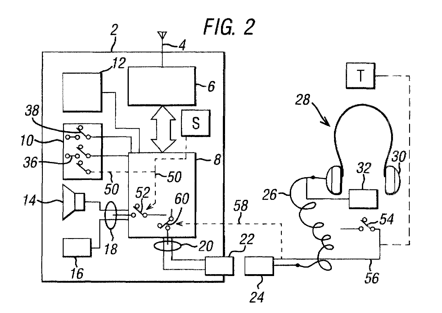
- a handset 2 has an antenna 4 coupled to a RF front end, or transceiver section, 6.
- a digital processing section 8 processes incoming and outgoing calls, and provides control functions. Section 8 is connected to a key pad 10, a display 12, a loudspeaker 14 and microphone 16. Loudspeaker 14 and microphone 16 are coupled to section 8 by lines which provide a first audio path indicated as at 18.
- a second audio path 20 from section 8 is connected to a socket 22 in the handset for connection with a plug 24 attached to one end of a lead or cord 26, the other end of which is connected to a headset 28 comprising headphones 30 and a microphone 32.
- a plug 24 attached to one end of a lead or cord 26, the other end of which is connected to a headset 28 comprising headphones 30 and a microphone 32.
- headset 28 comprising headphones 30 and a microphone 32.
- Key pad 10 includes a switch 36 for accepting an incoming call or initiating an outgoing call, and a switch 38 for terminating a call. Switches 36 and 38 are implemented as finger operable button switches.
- the mobile station may, throughout the day, be used in a variety of situations. For example, a user may 'wear' the headset during use in a motorcar, and then may wind the cord of the headset around the handset and put the handset in his pocket. In this situation, with the corded headset connected to the handset, but not worn on the user's head, it is difficult to answer an incoming call quickly. The user either has to unplug the headset or has to quickly 'wear' the headset. With a cordless headset, the difficulty for the user of knowing where the audio is routed, to the handset or headset, is increased.
- the concept of the invention is to provide a mechanism that is operative when an incoming call is accepted or outgoing call is initiated to transfer the audio to the most appropriate path for the user.
- a switch is provided on the handset and/or the headset which is provided with a dual function so that if the switch on the handset is actuated to receive a call, or initiate an outgoing call, the audio is automatically routed to the handset.
- the audio is automatically routed to the headset. Since the switch will be connected to a software control function, this automatic path selection may be varied by appropriate manipulation.
- a dedicated audio path switch is provided so that when an when a call is made, the user may select or toggle to the appropriate audio path.
- a mechanism for automatically detecting which of the handset or headset is being used by the operator, such mechanism being coupled to an audio path control to automatically route the audio to the set which is in use.
- a pressure detector may be provided on the headset clamping mechanism to indicate the headset is in use.
- a capacitive proximity detector may be provided on the handset to monitor the proximity of a user's head, to determine whether the handset is in use.
- a mobile station for a mobile telecommunications system comprising a handset and a headset for connection to the handset, the handset including RF transceiver means for transmitting an outgoing call and receiving an incoming call, processor means coupled to the RF transceiver means for providing audio signals on a first audio path to audio transducer means in the handset and on a second audio path for audio transducer means in the headset, characterised in that: the headset and/or the handset includes a switch means arranged such that operation thereof has the effect both of initiating and/or accepting a call, and of routing audio signals to a selected one of the first and second audio paths
- the invention provides a mobile station for a mobile telecommunications system, as aforesaid but characterised in that the headset and/or the handset includes a first switch means operative upon receipt of an incoming call to accept the call, and a second switch means, manually operable for toggling the audio path to a selected one of the loudspeaker and headset.
- the invention provides a mobile station for a mobile telecommunications system as aforesaid, but characterised by means for detecting use of the headset or handset by the user and coupled to audio path control means for automatically enabling the respective first or second audio path to the set in use.
- the present invention provides a mobile station for a mobile telecommunications system, comprising a handset and a headset arranged for coupling to the handset, and means operative upon acceptance of an incoming call to the station to selectively route the audio path to one of the headset and handset.
- the invention provides a method of operating a mobile station as aforesaid, the method being characterised by monitoring the handset for receipt of an incoming call, and if detected, operating said switch means to accept the call, and routing the audio to a selected one of the first and second audio paths, and if an incoming call is not detected, but said switch means is operated, initiating a call, and , and routing the audio to a selected one of the first and second audio paths.
- the invention consists of a dual function to the controls on the handset and/or headset that control call answering and initiation, or a dedicated audio path control on the handset and/or headset, or an automatic means of detection of the audio path in use, whereby the audio path for the call is routed to the appropriate path, or is transferred to the most suitable path at the user's operation of the control.
- the correct path is either automatically chosen, or can be chosen by the user in a simple and quick manner. For example:
- Button switch 36 in key pad 10 is coupled by a software control function indicated schematically at 50 to a switch 52 in the first audio path 18.
- Switch 52 is also indicated schematically; it will in practice be implemented as a transistor switch or switches within processing section 8.
- a further button switch 54 is provided in headset 28 and is coupled via a line 56 through connectors 22, 24 to processing section 8. This line 56 is coupled via a software function, indicated schematically as at 58, to control a switch 60 in the second audio path.
- switch 60 may be implemented as a transistor switch or switches in processing section 8.
- switch 36 when the mobile station indicates by ringing an incoming call, or when a user wishes to initiate a call, the user has the choice of operating switch 36 or switch 54. Which switch is operated will depend on the user's convenience. Clearly if the headset is not connected, then the handset switch 36 will be operated. Alternatively, if the headset is connected and in position for use, then headset switch 54 may be operated. If switch 36 is operated, the audio path 18 is completed to loudspeaker 14 and microphone 16 by closure of switch 52. If the headset switch 54 is operated, then the second audio path 20 to headset 28 is closed by closure of switch 60.
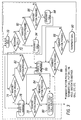
- FIG. 3 is a flowchart of a software routine that is stored in digital processing section 8 and that is responsive to the condition of switches 36 and 54 to close the appropriate audio path.
- an incoming call is monitored as at 72. If there is an incoming call and the handset button 36 is pressed, 74, then switch 52 is closed to route the audio on path 18 to the handset speaker and microphone 14, 16, as at 76.
- the handset button continues to be monitored, 78, and if depressed again, 80, the call is terminated or a call hold function is implemented, depending on the preconfiguring of the handset.
- the handset button is not pressed, a check is then made on the headset button 54 as at 82, 84. If button 54 is pressed then the audio is routed by closure of switch 60 on second audio path 20 to the headset, 85. Monitoring of the switches 36, 54 continues to take place, 86, 88 and if the handset button 36 is found to be depressed, then the audio is routed back to the first audio path, 76. If the headset button 54 is depressed, then the call is terminated, 90.
- the handset button switch 36 is nevertheless monitored, 92, and if found to be pressed, a call is originated or initiated, 94, and the first audio path to the handset is enabled, 76. If the handset button 36 is not depressed but monitoring of the headset button switch 54 shows it to be depressed, 96, then a call is originated or initiated, 98, and the second audio path 20 is enabled, 86. If the headset button 54 is not depressed then the software returns to idle state 70.
- a button switch 140 is provided in key pad 10, and this is coupled by a software control routine indicated schematically at 142 to switches 52 and 60 in the first and second audio paths 18, 20.
- a call is initiated or accepted by closure of switch 36, and the audio can be switched or toggled between the first and second audio paths at any time by actuation of toggle switch 140.
- FIG. 5 to 8 operate by an automatic sensing of the use of the handset or headset.
- the sensors are shown schematically in Figure 2 as S and T.
- Switch S is coupled to software link 50 for operation of switch 52 in first audio path 18.
- Switch T is linked by line 56 to software link 58, in order to operate switch 60 in second audio path 20.
- closure of automatic switch S or automatic switch T will have the effect of automatically enabling the respective first or second audio path 18, 20.
- sensor switch S is implemented as a pair of sensor electrodes 150 in the mobile handset 2 connected to a capacitance measuring circuit 152 and thence to a threshold circuit 154.
- a signal is provided by threshold circuit 154 to close switch 52, via software link 50.
- a infrared transmitter 160 provides an infrared beam which is reflected during use of the handset by head to an infrared receiver 162.
- the infrared receiver is coupled to a threshold circuit 164 which provides a switch closure signal for switch 52 in audio path 18.
- an audio transducer 170 is provided in the handset.
- a driving circuit 172 provides an electric signal to the transducer 170, and also detects the electrical impedance of the transducer. When the ear is held close to the transducer, the sound waves generated by the transducer will be channelled into the ear canal, and the apparent impedance of the transducer will change. This change is detected by driving circuit 172 and employed to switch 52 in first audio path 18.
- a headset comprising a pair of headphones 180 with a headset band 182.
- a switch 184 is provided on the headset band 182.
- the switch may be of any type reacting to mechanical stress, for example, piezoelectric or magnetostrictive. Closure of the switch causes closure of switch 60 in second audio path 20.
Landscapes
- Engineering & Computer Science (AREA)
- Signal Processing (AREA)
- Health & Medical Sciences (AREA)
- Otolaryngology (AREA)
- Telephone Function (AREA)
- Mobile Radio Communication Systems (AREA)
- Telephone Set Structure (AREA)
Abstract
Description
- The present invention relates to a mobile station for a mobile telecommunications system, in particular a mobile handset with an associated headset.
- Mobile handsets with associated headsets are in common use. The headset is to enable handsfree operation and may be corded or cordless. The cord of a corded headset has a terminating plug which is inserted into a terminal in the handset to provide an audio path to the headset. A cordless headset is coupled with the handset by a subsidiary wireless link. The arrangement is shown schematically in Figure 1. A
handset 2 has anantenna 4 coupled to a RF front end, or transceiver section, 6. Adigital processing section 8 processes incoming and outgoing calls, and provides control functions.Section 8 is connected to akey pad 10, adisplay 12, aloudspeaker 14 andmicrophone 16. Loudspeaker 14 andmicrophone 16 are coupled tosection 8 by lines which provide a first audio path indicated as at 18. Asecond audio path 20 fromsection 8 is connected to asocket 22 in the handset for connection with aplug 24 attached to one end of a lead orcord 26, the other end of which is connected to aheadset 28 comprisingheadphones 30 and amicrophone 32. When theplug 24 is plugged into the socket, audio is automatically routed to the headset.Key pad 10 includes aswitch 36 for accepting an incoming call or initiating an outgoing call, and aswitch 38 for terminating a call.Switches - The mobile station may, throughout the day, be used in a variety of situations. For example, a user may 'wear' the headset during use in a motorcar, and then may wind the cord of the headset around the handset and put the handset in his pocket. In this situation, with the corded headset connected to the handset, but not worn on the user's head, it is difficult to answer an incoming call quickly. The user either has to unplug the headset or has to quickly 'wear' the headset. With a cordless headset, the difficulty for the user of knowing where the audio is routed, to the handset or headset, is increased.
- Thus, there is a problem that may arise in a variety of situations for the user to ascertain where the audio path is routed and what is the most effective way of answering an incoming call. In an extreme situation, an incoming call may be lost.
- One possible solution of routing the audio simultaneously both to the handset and to the headset would not be practical, since there would be a great amount of audio feedback resulting in acoustic echo, wherein the handset microphone picks up the generated audio. In addition there would be much degraded ambient noise pick up, adversely affecting listener side tone and send audio noise performance.
- It is an object of the present invention to overcome or at least reduce the above noted problem.
- The concept of the invention is to provide a mechanism that is operative when an incoming call is accepted or outgoing call is initiated to transfer the audio to the most appropriate path for the user.
- In one form of the invention, a switch is provided on the handset and/or the headset which is provided with a dual function so that if the switch on the handset is actuated to receive a call, or initiate an outgoing call, the audio is automatically routed to the handset. Alternatively, if a switch located on the headset is actuated to receive or initiate a call, then the audio is automatically routed to the headset. Since the switch will be connected to a software control function, this automatic path selection may be varied by appropriate manipulation.
- In a further form of the invention a dedicated audio path switch is provided so that when an when a call is made, the user may select or toggle to the appropriate audio path.
- In a further form of the invention, a mechanism is provided for automatically detecting which of the handset or headset is being used by the operator, such mechanism being coupled to an audio path control to automatically route the audio to the set which is in use. For example, a pressure detector may be provided on the headset clamping mechanism to indicate the headset is in use. Alternatively, a capacitive proximity detector may be provided on the handset to monitor the proximity of a user's head, to determine whether the handset is in use.
- Accordingly, the invention provides in a first aspect, a mobile station for a mobile telecommunications system comprising a handset and a headset for connection to the handset,
the handset including RF transceiver means for transmitting an outgoing call and receiving an incoming call, processor means coupled to the RF transceiver means for providing audio signals on a first audio path to audio transducer means in the handset and on a second audio path for audio transducer means in the headset, characterised in that:
the headset and/or the handset includes a switch means arranged such that operation thereof has the effect both of initiating and/or accepting a call, and of routing audio signals to a selected one of the first and second audio paths - In a second aspect, the invention provides a mobile station for a mobile telecommunications system, as aforesaid but characterised in that the headset and/or the handset includes a first switch means operative upon receipt of an incoming call to accept the call, and a second switch means, manually operable for toggling the audio path to a selected one of the loudspeaker and headset.
- In a third aspect, the invention provides a mobile station for a mobile telecommunications system as aforesaid, but characterised by means for detecting use of the headset or handset by the user and coupled to audio path control means for automatically enabling the respective first or second audio path to the set in use.
- In a more general aspect, the present invention provides a mobile station for a mobile telecommunications system, comprising a handset and a headset arranged for coupling to the handset, and means operative upon acceptance of an incoming call to the station to selectively route the audio path to one of the headset and handset.
- In a fourth aspect, the invention provides a method of operating a mobile station as aforesaid, the method being characterised by monitoring the handset for receipt of an incoming call, and if detected, operating said switch means to accept the call, and routing the audio to a selected one of the first and second audio paths, and if an incoming call is not detected, but said switch means is operated, initiating a call, and , and routing the audio to a selected one of the first and second audio paths.
- Preferred embodiments of the invention will now be described with reference to the accompanying drawings, wherein:
- Figure 1 is a schematic view of a known mobile station comprising a handset and corded headset;
- Figure 2 is a schematic view of a mobile station according to a first embodiment of the invention and employing dual function keys for automatic routing of the audio path;
- Figure 3 is a flowchart illustrating the operation of the dual function keys of the embodiment of Figure 2 for appropriate routing of the audio path;
- Figure 4 is a schematic view of a second embodiment of the invention, with a separate audio path toggle control; and
- Figures 5 to 8 are diagrams of various automatic means for detecting use of a handset or headset, incorporated in further embodiments of the invention.
-
- The invention consists of a dual function to the controls on the handset and/or headset that control call answering and initiation, or a dedicated audio path control on the handset and/or headset, or an automatic means of detection of the audio path in use, whereby the audio path for the call is routed to the appropriate path, or is transferred to the most suitable path at the user's operation of the control. Thus, the correct path is either automatically chosen, or can be chosen by the user in a simple and quick manner. For example:
- With headset connected (whether via a cord or cordlessly, wire or wirelessly), if incoming call answered or initiated using call control (typically a switch button) on the headset, audio automatically routed to headset.
- With headset connected, if incoming call answered on handset, then audio automatically routed to handset. In case of call initiated on handset, optional set default routing to headset or handset.
- With headset connected, if incoming call answered or initiated on handset, and following that the control on the headset is activated, audio transfers from the handset to the headset.
- With headset connected, if incoming call answered or initiated on the headset, and following that the control on the handset is activated, audio transfers from the headset to the handset.
- Further control operation transfers the call as expected, or terminates the call if the control on the apparatus currently selected is operated again.
- Where no headset is connected, audio routes to handset.
- Referring now to Figure 2, similar parts to those shown in Figure 1 are indicated by the same reference numeral.
Button switch 36 inkey pad 10 is coupled by a software control function indicated schematically at 50 to aswitch 52 in thefirst audio path 18.Switch 52 is also indicated schematically; it will in practice be implemented as a transistor switch or switches withinprocessing section 8. Afurther button switch 54 is provided inheadset 28 and is coupled via aline 56 throughconnectors processing section 8. Thisline 56 is coupled via a software function, indicated schematically as at 58, to control aswitch 60 in the second audio path. Again,switch 60 may be implemented as a transistor switch or switches inprocessing section 8. - Thus, in operation, when the mobile station indicates by ringing an incoming call, or when a user wishes to initiate a call, the user has the choice of
operating switch 36 or switch 54. Which switch is operated will depend on the user's convenience. Clearly if the headset is not connected, then thehandset switch 36 will be operated. Alternatively, if the headset is connected and in position for use, thenheadset switch 54 may be operated. Ifswitch 36 is operated, theaudio path 18 is completed toloudspeaker 14 andmicrophone 16 by closure ofswitch 52. If theheadset switch 54 is operated, then thesecond audio path 20 toheadset 28 is closed by closure ofswitch 60. - Referring now to Figure 3, this is a flowchart of a software routine that is stored in
digital processing section 8 and that is responsive to the condition ofswitches idle state 70, an incoming call is monitored as at 72. If there is an incoming call and thehandset button 36 is pressed, 74, then switch 52 is closed to route the audio onpath 18 to the handset speaker andmicrophone - If at 74 or at 78, the handset button is not pressed, a check is then made on the
headset button 54 as at 82, 84. Ifbutton 54 is pressed then the audio is routed by closure ofswitch 60 on secondaudio path 20 to the headset, 85. Monitoring of theswitches handset button 36 is found to be depressed, then the audio is routed back to the first audio path, 76. If theheadset button 54 is depressed, then the call is terminated, 90. - Referring back to
decision point 72, if there is not an incoming call, thehandset button switch 36 is nevertheless monitored, 92, and if found to be pressed, a call is originated or initiated, 94, and the first audio path to the handset is enabled, 76. If thehandset button 36 is not depressed but monitoring of theheadset button switch 54 shows it to be depressed, 96, then a call is originated or initiated, 98, and thesecond audio path 20 is enabled, 86. If theheadset button 54 is not depressed then the software returns to idlestate 70. - The software function shown in Figure 3 for call initiation and answering can be put under user control (instead of following the sequence as above) using, for example, short and long button presses, or double-click action.
- Referring now to Figure 4, similar parts to those shown in Figure 2 are denoted by the same reference numeral. A
button switch 140 is provided inkey pad 10, and this is coupled by a software control routine indicated schematically at 142 toswitches second audio paths switch 36, and the audio can be switched or toggled between the first and second audio paths at any time by actuation oftoggle switch 140. - The embodiments shown in Figures 5 to 8 operate by an automatic sensing of the use of the handset or headset. The sensors are shown schematically in Figure 2 as S and T. Switch S is coupled to
software link 50 for operation ofswitch 52 in firstaudio path 18. Switch T is linked byline 56 tosoftware link 58, in order to operateswitch 60 in secondaudio path 20. Thus, closure of automatic switch S or automatic switch T will have the effect of automatically enabling the respective first or secondaudio path - Referring to Figure 5, sensor switch S is implemented as a pair of
sensor electrodes 150 in themobile handset 2 connected to acapacitance measuring circuit 152 and thence to athreshold circuit 154. When the capacitance sensed by theelectrodes 150 increases as it is brought near the head, a signal is provided bythreshold circuit 154 to closeswitch 52, viasoftware link 50. - In Figure 6, a
infrared transmitter 160 provides an infrared beam which is reflected during use of the handset by head to an infrared receiver 162. The infrared receiver is coupled to a threshold circuit 164 which provides a switch closure signal forswitch 52 inaudio path 18. - In Figure 7, an audio transducer 170 is provided in the handset. A driving
circuit 172 provides an electric signal to the transducer 170, and also detects the electrical impedance of the transducer. When the ear is held close to the transducer, the sound waves generated by the transducer will be channelled into the ear canal, and the apparent impedance of the transducer will change. This change is detected by drivingcircuit 172 and employed to switch 52 in firstaudio path 18. - In Figure 8, a headset is provided comprising a pair of
headphones 180 with aheadset band 182. Aswitch 184 is provided on theheadset band 182. When theheadset band 182 is tensioned by being placed on the head, the switch is closed by the tension in the headset band. The switch may be of any type reacting to mechanical stress, for example, piezoelectric or magnetostrictive. Closure of the switch causes closure ofswitch 60 in secondaudio path 20. - It is possible in all the above embodiments to optionally indicate (using LED, LCD icon, etc.), of where the audio is currently routed.
- The present invention provides the following advantages:
- Simplified use of headset with mobile phone, avoiding user frustration.
- Enhanced human factor performance.
- Enhanced customer satisfaction.
Claims (18)
- A mobile station for a mobile telecommunications system comprising a handset (2) and a headset (28) for connection to the handset,
the handset including RF transceiver means (6) for transmitting an outgoing call and receiving an incoming call, processor means (8) coupled to the RF transceiver means for providing audio signals on a first audio path (18) to audio transducer means (14, 16) in the handset and on a second audio path (20) for audio transducer means in the headset, characterised in that:
the headset and/or the handset includes a switch means (36, 54) arranged such that operation thereof has the effect both of initiating and/or accepting a call, and of routing audio signals to a selected one of the first and second audio paths. - A mobile station according to claim 1, wherein the audio transducer means in the headset and handset each comprise a microphone (16, 32) and loudspeaker (14, 30).
- A mobile station according to claim 1 or 2, wherein the first mentioned switch means (36) is located in the handset and a second switch means (54) having similar functions is located in the headset.
- A mobile station according to any preceding claim, including switch control means (50, 58) in the processor means responsive to operation of the first mentioned switch means, for operating respective further switch means (52, 60) in the first audio path and in the second audio path for selection thereof.
- A mobile station according to any preceding claim, wherein further operation of the first switch means is operative to terminate a call.
- A mobile station according to claim 3, wherein the first switch means is located in the handset and a second switch means (54) having similar functions is located in the headset, and wherein operation of the first switch means followed by operation of the second switch means, or vice versa, is effective to select the other of the selected one of the first and second audio paths.
- A mobile station according to any preceding claim, arranged such that further operation of the first mentioned switch means is operative to terminate a call.
- A mobile station for a mobile telecommunications system comprising a handset (2) and a headset (28) for connection to the handset,
the handset including RF transceiver means (6) for transmitting an outgoing call and receiving an incoming call, processor means (8) coupled to the RF transceiver means for providing audio signals on a first audio path (18) to audio transducer means (14, 16) in the handset and on a second audio path (20) for audio transducer means in the headset, characterised in that:
the headset and/or the handset includes a first switch means (36) operative upon receipt of an incoming call to accept the call, and a second switch means (140), manually operable for toggling the audio path to a selected one of the loudspeaker and headset. - A mobile station for a mobile telecommunications system comprising a handset (2) and a headset (28) for connection to the handset,
the handset including RF transceiver means (6) for transmitting an outgoing call and receiving an incoming call, processor means (8) coupled to the RF transceiver means for providing audio signals on a first audio path (18) to audio transducer means (14, 16) in the handset and on a second audio path (20) for audio transducer means in the headset, characterised by:
means (S, T) for detecting use of the headset or handset by the user and coupled to audio path control means (50, 58) for automatically enabling the respective first or second audio path to the set in use. - A mobile station according to claim 9, wherein the detecting means comprises a capacitance sensing means (150- 154) located in the handset for detecting proximity of a user's head.
- A mobile station according to claim 9, wherein the detecting means comprises infrared sensing means (160- 164) located in the handset for detecting proximity of a user's head.
- A mobile station according to claim 9, wherein the detecting means comprises acoustic impedance sensing means (170- 172) located in the handset for detecting proximity of a user's head.
- A mobile station according to claim 9, wherein the detecting means comprises sensing means (184) located in the headband (182) of the handset for detecting use on a user's head.
- A mobile station for a mobile telecommunications system comprising a handset (2) and a headset (28) for connection to the handset,
the handset including RF transceiver means (6) for transmitting an outgoing call and receiving an incoming call, processor means (8) coupled to the RF transceiver means for providing audio signals on a first audio path (18) to audio transducer means (14, 16) in the handset and on a second audio path (20) for audio transducer means in the headset, characterised by:
means (36, 54, 140, 150- 184) operative upon initiation of an outgoing call or acceptance of an incoming call to the station to selectively route the audio path to one of the headset and handset. - A method of operating a mobile station for a mobile telecommunications system , the mobile station comprising a handset (2) and a headset (28) for connection to the handset, the handset including RF transceiver means (6) for transmitting an outgoing call and receiving an incoming call, processor means (8) coupled to the RF transceiver means for providing audio signals on a first audio path (18) to audio transducer means (14, 16) in the handset and on a second audio path (20) for audio transducer means in the headset, and switch means (36) for accepting or initiating a call,
the method being characterised by monitoring the handset for receipt of an incoming call (72) and if detected, operating said switch means to accept the call (74, 82), and routing the audio to a selected one of the first and second audio paths (76, 85), and if an incoming call is not detected, but said switch means is operated (92, 96), initiating a call (94, 98), and routing the audio to a selected one of the first and second audio paths (76, 85). - A method according to claim 15, including further operating the switch means in order to terminate the call (90).
- A method according to claim 15 or 16, wherein the first mentioned switch means (36) is located in the handset and a second switch means (54) having similar functions is located in the headset, and depending on which of the first and second switch means is operated, the audio is routed to the respective set.
- A method according to claim 17, comprising operating one switch means following operation of the other switch means (78, 84; 74, 82), whereby to route the audio to the audio path not currently in use.
Priority Applications (3)
| Application Number | Priority Date | Filing Date | Title |
|---|---|---|---|
| EP00303977A EP1154621B1 (en) | 2000-05-11 | 2000-05-11 | Mobile station for telecommunications system |
| DE60037878T DE60037878T2 (en) | 2000-05-11 | 2000-05-11 | Mobile station for telecommunication system |
| US09/854,256 US7433715B2 (en) | 2000-05-11 | 2001-05-11 | Mobile station for telecommunications system |
Applications Claiming Priority (1)
| Application Number | Priority Date | Filing Date | Title |
|---|---|---|---|
| EP00303977A EP1154621B1 (en) | 2000-05-11 | 2000-05-11 | Mobile station for telecommunications system |
Publications (2)
| Publication Number | Publication Date |
|---|---|
| EP1154621A1 true EP1154621A1 (en) | 2001-11-14 |
| EP1154621B1 EP1154621B1 (en) | 2008-01-23 |
Family
ID=8172980
Family Applications (1)
| Application Number | Title | Priority Date | Filing Date |
|---|---|---|---|
| EP00303977A Expired - Lifetime EP1154621B1 (en) | 2000-05-11 | 2000-05-11 | Mobile station for telecommunications system |
Country Status (3)
| Country | Link |
|---|---|
| US (1) | US7433715B2 (en) |
| EP (1) | EP1154621B1 (en) |
| DE (1) | DE60037878T2 (en) |
Cited By (8)
| Publication number | Priority date | Publication date | Assignee | Title |
|---|---|---|---|---|
| EP1326410A1 (en) * | 2002-01-08 | 2003-07-09 | CCM Europe | Handsfree wireless communication system for handsfree communication between a user and a mobile phone |
| EP1335568A3 (en) * | 2002-02-11 | 2004-03-10 | Sharp Kabushiki Kaisha | Call operation method for a communication device |
| EP1265422A4 (en) * | 2001-02-09 | 2007-09-05 | Sony Corp | PORTABLE RADIO TERMINAL, SOUND DIFFUSION METHOD, AND SOUND TAKING METHOD |
| WO2007140821A1 (en) | 2006-06-02 | 2007-12-13 | Sony Ericsson Mobile Communications Ab | Sound output selection in relation to an accessory |
| WO2007110807A3 (en) * | 2006-03-24 | 2008-03-13 | Koninkl Philips Electronics Nv | Data processing for a waerable apparatus |
| US7433715B2 (en) | 2000-05-11 | 2008-10-07 | Agere Systems, Inc. | Mobile station for telecommunications system |
| CN101461218A (en) * | 2006-06-02 | 2009-06-17 | 索尼爱立信移动通讯股份有限公司 | Sound output selection for accessories |
| EP2775693A3 (en) * | 2013-03-05 | 2017-07-26 | Sony Mobile Communications AB | Automatic routing of call audio at incoming call |
Families Citing this family (22)
| Publication number | Priority date | Publication date | Assignee | Title |
|---|---|---|---|---|
| US7373182B2 (en) * | 2002-03-01 | 2008-05-13 | Varia Mobil Llc | Wireless mobile phone including a headset |
| JP4125036B2 (en) * | 2002-04-24 | 2008-07-23 | 松下電器産業株式会社 | Mobile terminal device |
| US6873884B2 (en) * | 2002-11-26 | 2005-03-29 | Ge Medical Systems Information Technology | Computer-equipped mobility device and method of connecting to a network |
| JP4167533B2 (en) * | 2003-04-16 | 2008-10-15 | Necインフロンティア株式会社 | Call system |
| US20050179056A1 (en) * | 2004-02-18 | 2005-08-18 | Teggatz Ross E. | System for resonant circuit tuning |
| CN1848870A (en) * | 2005-04-05 | 2006-10-18 | 摩托罗拉公司 | Communication apparatus and method for automatic answering incoming call |
| US7577459B2 (en) * | 2005-05-11 | 2009-08-18 | Nokia Corporation | Establishing a communication link |
| JP4591257B2 (en) * | 2005-07-27 | 2010-12-01 | 株式会社デンソー | Hands-free device |
| US8031878B2 (en) * | 2005-07-28 | 2011-10-04 | Bose Corporation | Electronic interfacing with a head-mounted device |
| JP2007067742A (en) * | 2005-08-30 | 2007-03-15 | Kyocera Corp | Mobile phone |
| US20070093279A1 (en) * | 2005-10-12 | 2007-04-26 | Craig Janik | Wireless headset system for the automobile |
| US7627352B2 (en) * | 2006-03-27 | 2009-12-01 | Gauger Jr Daniel M | Headset audio accessory |
| US9055413B2 (en) * | 2006-11-06 | 2015-06-09 | Plantronics, Inc. | Presence over existing cellular and land-line telephone networks |
| US9591392B2 (en) * | 2006-11-06 | 2017-03-07 | Plantronics, Inc. | Headset-derived real-time presence and communication systems and methods |
| US7920903B2 (en) * | 2007-01-04 | 2011-04-05 | Bose Corporation | Microphone techniques |
| CN101640720A (en) * | 2008-07-31 | 2010-02-03 | 鸿富锦精密工业(深圳)有限公司 | Mobile communication terminal and switching method of answer mode thereof |
| US8583176B2 (en) * | 2009-01-06 | 2013-11-12 | Blackberry Limited | Automatic audio routing dependent on dock state |
| KR101694420B1 (en) * | 2009-09-03 | 2017-01-09 | 삼성전자주식회사 | Apparatus and method for improving of communication quality in a mobile terminal |
| EP2702752B1 (en) * | 2011-04-27 | 2019-09-18 | BlackBerry Limited | System and method for automatically answering a call on a communication device |
| US20130149990A1 (en) * | 2011-12-07 | 2013-06-13 | Kevin Otto | Wireless Communication Apparatus for Emergency Situations |
| KR20150033472A (en) * | 2013-09-24 | 2015-04-01 | 삼성전자주식회사 | Method for sharing status information and an electronic device thereof |
| CN110602312B (en) * | 2019-08-21 | 2021-05-11 | 华为技术有限公司 | Call method, electronic device and computer readable storage medium |
Citations (4)
| Publication number | Priority date | Publication date | Assignee | Title |
|---|---|---|---|---|
| US5191602A (en) * | 1991-01-09 | 1993-03-02 | Plantronics, Inc. | Cellular telephone headset |
| US5504812A (en) * | 1994-10-11 | 1996-04-02 | Motorola, Inc. | Headset for use with a radiotelephone |
| EP0840465A2 (en) * | 1996-10-31 | 1998-05-06 | Nokia Mobile Phones Ltd. | User interface for mobile telephone |
| EP0912031A2 (en) * | 1997-10-24 | 1999-04-28 | Nortel Networks Corporation | Light guide implementation of a proximity detector |
Family Cites Families (11)
| Publication number | Priority date | Publication date | Assignee | Title |
|---|---|---|---|---|
| JPS607231A (en) * | 1983-06-27 | 1985-01-16 | Toshiba Corp | On-vehicle loudspeaker telephone set |
| US5227667A (en) * | 1989-01-10 | 1993-07-13 | Omron Corporation | Microwave proximity switch |
| US5224151A (en) * | 1992-04-01 | 1993-06-29 | At&T Bell Laboratories | Automatic handset-speakephone switching arrangement for portable communication device |
| JP2784396B2 (en) * | 1994-06-08 | 1998-08-06 | セイコープレシジョン株式会社 | Capacitive sensor |
| US5729604A (en) * | 1996-03-14 | 1998-03-17 | Northern Telecom Limited | Safety switch for communication device |
| US6038457A (en) * | 1997-12-05 | 2000-03-14 | Motorola, Inc. | Apparatus and method for detecting and powering an accessory |
| US6115620A (en) * | 1998-05-20 | 2000-09-05 | Motorola, Inc. | Mode-switchable portable communication device and method therefor |
| KR100265283B1 (en) * | 1998-06-12 | 2000-09-15 | 윤종용 | Method for enhancing reliability of hard disk drive by use of head mapping |
| EP0999721A3 (en) * | 1998-11-07 | 2003-05-21 | Samsung Electronics Co., Ltd. | Device for controlling connection of built-in type ear-microphone for portable radio terminal |
| US6434407B1 (en) * | 1999-12-03 | 2002-08-13 | Denso Corporation, Ltd. | Speakerphone feature for a wireless handset |
| DE60037878T2 (en) | 2000-05-11 | 2009-01-22 | Lucent Technologies Inc. | Mobile station for telecommunication system |
-
2000
- 2000-05-11 DE DE60037878T patent/DE60037878T2/en not_active Expired - Lifetime
- 2000-05-11 EP EP00303977A patent/EP1154621B1/en not_active Expired - Lifetime
-
2001
- 2001-05-11 US US09/854,256 patent/US7433715B2/en not_active Expired - Fee Related
Patent Citations (4)
| Publication number | Priority date | Publication date | Assignee | Title |
|---|---|---|---|---|
| US5191602A (en) * | 1991-01-09 | 1993-03-02 | Plantronics, Inc. | Cellular telephone headset |
| US5504812A (en) * | 1994-10-11 | 1996-04-02 | Motorola, Inc. | Headset for use with a radiotelephone |
| EP0840465A2 (en) * | 1996-10-31 | 1998-05-06 | Nokia Mobile Phones Ltd. | User interface for mobile telephone |
| EP0912031A2 (en) * | 1997-10-24 | 1999-04-28 | Nortel Networks Corporation | Light guide implementation of a proximity detector |
Cited By (11)
| Publication number | Priority date | Publication date | Assignee | Title |
|---|---|---|---|---|
| US7433715B2 (en) | 2000-05-11 | 2008-10-07 | Agere Systems, Inc. | Mobile station for telecommunications system |
| EP1265422A4 (en) * | 2001-02-09 | 2007-09-05 | Sony Corp | PORTABLE RADIO TERMINAL, SOUND DIFFUSION METHOD, AND SOUND TAKING METHOD |
| EP1326410A1 (en) * | 2002-01-08 | 2003-07-09 | CCM Europe | Handsfree wireless communication system for handsfree communication between a user and a mobile phone |
| EP1335568A3 (en) * | 2002-02-11 | 2004-03-10 | Sharp Kabushiki Kaisha | Call operation method for a communication device |
| US7027841B2 (en) | 2002-02-11 | 2006-04-11 | Sharp Laboratories Of America, Inc. | Call operation method for a communication device |
| WO2007110807A3 (en) * | 2006-03-24 | 2008-03-13 | Koninkl Philips Electronics Nv | Data processing for a waerable apparatus |
| WO2007140821A1 (en) | 2006-06-02 | 2007-12-13 | Sony Ericsson Mobile Communications Ab | Sound output selection in relation to an accessory |
| CN101461218A (en) * | 2006-06-02 | 2009-06-17 | 索尼爱立信移动通讯股份有限公司 | Sound output selection for accessories |
| US7930007B2 (en) | 2006-06-02 | 2011-04-19 | Sony Ericsson Mobile Communications Ab | Audio output device selection for a portable electronic device |
| EP2775693A3 (en) * | 2013-03-05 | 2017-07-26 | Sony Mobile Communications AB | Automatic routing of call audio at incoming call |
| EP3429174A1 (en) * | 2013-03-05 | 2019-01-16 | Sony Mobile Communications Inc. | Automatic routing of call audio at incoming call |
Also Published As
| Publication number | Publication date |
|---|---|
| US7433715B2 (en) | 2008-10-07 |
| DE60037878D1 (en) | 2008-03-13 |
| US20020049079A1 (en) | 2002-04-25 |
| EP1154621B1 (en) | 2008-01-23 |
| DE60037878T2 (en) | 2009-01-22 |
Similar Documents
| Publication | Publication Date | Title |
|---|---|---|
| US7433715B2 (en) | Mobile station for telecommunications system | |
| CN1047703C (en) | Cellular telephone | |
| JPH0273751A (en) | Cordless telephone set | |
| US7702368B2 (en) | Apparatus and method for controlling speaker volume of push-to-talk (PTT) phone | |
| US20080075272A1 (en) | Telephone Communication Apparatus | |
| JPH06216978A (en) | Transmitter-receiver | |
| EP1531606A1 (en) | Collapsible mobile telephone | |
| JPH11163989A (en) | Mobile phone | |
| JPH11163987A (en) | Telephone | |
| JPH08125726A (en) | Two-way handset handset | |
| KR200261461Y1 (en) | hands free for music player | |
| JP3893285B2 (en) | Mobile phone | |
| KR100621749B1 (en) | Mobile communication terminal and method of changing incoming call notification mode of mobile communication terminal using the same | |
| JPS61169055A (en) | Key telephone device | |
| KR200259991Y1 (en) | Charger of mobile phone comprising adaptor for connecting a mobile phone and a telephonic handset | |
| JPH04354234A (en) | Telephone set | |
| KR100450139B1 (en) | Ear-mike having the receiving and sending buttons and mobile communication terminal using the same | |
| JP3024412B2 (en) | Handset | |
| JP3056854B2 (en) | Telephone equipment | |
| KR200299965Y1 (en) | Device for connecting the Ear Set to Telephone | |
| JPH03212045A (en) | Cordless telephone system | |
| JP3704456B2 (en) | Telephone | |
| KR200305251Y1 (en) | Apparatus Receiving Sound having receiving selection means between speaker and earphone | |
| JPH09252341A (en) | Telephone equipment | |
| KR200205580Y1 (en) | Apparatus for headset type terminal comprising audio output function in communication system |
Legal Events
| Date | Code | Title | Description |
|---|---|---|---|
| PUAI | Public reference made under article 153(3) epc to a published international application that has entered the european phase |
Free format text: ORIGINAL CODE: 0009012 |
|
| AK | Designated contracting states |
Kind code of ref document: A1 Designated state(s): DE FI FR GB SE Kind code of ref document: A1 Designated state(s): AT BE CH CY DE DK ES FI FR GB GR IE IT LI LU MC NL PT SE |
|
| AX | Request for extension of the european patent |
Free format text: AL;LT;LV;MK;RO;SI |
|
| 17P | Request for examination filed |
Effective date: 20020510 |
|
| AKX | Designation fees paid |
Free format text: DE FI FR GB SE |
|
| GRAP | Despatch of communication of intention to grant a patent |
Free format text: ORIGINAL CODE: EPIDOSNIGR1 |
|
| GRAS | Grant fee paid |
Free format text: ORIGINAL CODE: EPIDOSNIGR3 |
|
| GRAA | (expected) grant |
Free format text: ORIGINAL CODE: 0009210 |
|
| AK | Designated contracting states |
Kind code of ref document: B1 Designated state(s): DE FI FR GB SE |
|
| REG | Reference to a national code |
Ref country code: GB Ref legal event code: FG4D |
|
| REF | Corresponds to: |
Ref document number: 60037878 Country of ref document: DE Date of ref document: 20080313 Kind code of ref document: P |
|
| REG | Reference to a national code |
Ref country code: SE Ref legal event code: TRGR |
|
| ET | Fr: translation filed | ||
| PLBE | No opposition filed within time limit |
Free format text: ORIGINAL CODE: 0009261 |
|
| STAA | Information on the status of an ep patent application or granted ep patent |
Free format text: STATUS: NO OPPOSITION FILED WITHIN TIME LIMIT |
|
| 26N | No opposition filed |
Effective date: 20081024 |
|
| PGFP | Annual fee paid to national office [announced via postgrant information from national office to epo] |
Ref country code: FI Payment date: 20140512 Year of fee payment: 15 Ref country code: FR Payment date: 20140509 Year of fee payment: 15 Ref country code: SE Payment date: 20140513 Year of fee payment: 15 |
|
| REG | Reference to a national code |
Ref country code: DE Ref legal event code: R082 Ref document number: 60037878 Country of ref document: DE Representative=s name: DILG HAEUSLER SCHINDELMANN PATENTANWALTSGESELL, DE |
|
| PGFP | Annual fee paid to national office [announced via postgrant information from national office to epo] |
Ref country code: GB Payment date: 20150424 Year of fee payment: 16 |
|
| PG25 | Lapsed in a contracting state [announced via postgrant information from national office to epo] |
Ref country code: FI Free format text: LAPSE BECAUSE OF NON-PAYMENT OF DUE FEES Effective date: 20150511 |
|
| REG | Reference to a national code |
Ref country code: FR Ref legal event code: ST Effective date: 20160129 |
|
| PG25 | Lapsed in a contracting state [announced via postgrant information from national office to epo] |
Ref country code: SE Free format text: LAPSE BECAUSE OF NON-PAYMENT OF DUE FEES Effective date: 20150512 |
|
| PG25 | Lapsed in a contracting state [announced via postgrant information from national office to epo] |
Ref country code: FR Free format text: LAPSE BECAUSE OF NON-PAYMENT OF DUE FEES Effective date: 20150601 |
|
| GBPC | Gb: european patent ceased through non-payment of renewal fee |
Effective date: 20160511 |
|
| PG25 | Lapsed in a contracting state [announced via postgrant information from national office to epo] |
Ref country code: GB Free format text: LAPSE BECAUSE OF NON-PAYMENT OF DUE FEES Effective date: 20160511 |
|
| REG | Reference to a national code |
Ref country code: DE Ref legal event code: R082 Ref document number: 60037878 Country of ref document: DE Representative=s name: DILG HAEUSLER SCHINDELMANN PATENTANWALTSGESELL, DE Ref country code: DE Ref legal event code: R081 Ref document number: 60037878 Country of ref document: DE Owner name: AVAGO TECHNOLOGIES GENERAL IP (SINGAPORE) PTE., SG Free format text: FORMER OWNER: LUCENT TECHNOLOGIES INC., MURRAY HILL, N.J., US Ref country code: DE Ref legal event code: R081 Ref document number: 60037878 Country of ref document: DE Owner name: AVAGO TECHNOLOGIES INTERNATIONAL SALES PTE. LI, SG Free format text: FORMER OWNER: LUCENT TECHNOLOGIES INC., MURRAY HILL, N.J., US |
|
| REG | Reference to a national code |
Ref country code: DE Ref legal event code: R081 Ref document number: 60037878 Country of ref document: DE Owner name: AVAGO TECHNOLOGIES INTERNATIONAL SALES PTE. LI, SG Free format text: FORMER OWNER: AVAGO TECHNOLOGIES GENERAL IP (SINGAPORE) PTE. LTD., SINGAPORE, SG Ref country code: DE Ref legal event code: R082 Ref document number: 60037878 Country of ref document: DE Representative=s name: DILG HAEUSLER SCHINDELMANN PATENTANWALTSGESELL, DE |
|
| PGFP | Annual fee paid to national office [announced via postgrant information from national office to epo] |
Ref country code: DE Payment date: 20190530 Year of fee payment: 20 |
|
| REG | Reference to a national code |
Ref country code: DE Ref legal event code: R071 Ref document number: 60037878 Country of ref document: DE |