EP1154586A1 - Equaliser - Google Patents
Equaliser Download PDFInfo
- Publication number
- EP1154586A1 EP1154586A1 EP00830343A EP00830343A EP1154586A1 EP 1154586 A1 EP1154586 A1 EP 1154586A1 EP 00830343 A EP00830343 A EP 00830343A EP 00830343 A EP00830343 A EP 00830343A EP 1154586 A1 EP1154586 A1 EP 1154586A1
- Authority
- EP
- European Patent Office
- Prior art keywords
- line
- attenuation
- bias current
- zero
- pole
- Prior art date
- Legal status (The legal status is an assumption and is not a legal conclusion. Google has not performed a legal analysis and makes no representation as to the accuracy of the status listed.)
- Granted
Links
- 230000003044 adaptive effect Effects 0.000 claims abstract description 14
- 238000000034 method Methods 0.000 claims abstract description 14
- 238000005516 engineering process Methods 0.000 claims description 4
- 239000003990 capacitor Substances 0.000 description 12
- 238000010586 diagram Methods 0.000 description 7
- 230000001419 dependent effect Effects 0.000 description 3
- 230000005540 biological transmission Effects 0.000 description 2
- 239000006185 dispersion Substances 0.000 description 2
- 238000006073 displacement reaction Methods 0.000 description 2
- 238000010276 construction Methods 0.000 description 1
- 230000000694 effects Effects 0.000 description 1
- 238000001914 filtration Methods 0.000 description 1
- 230000035484 reaction time Effects 0.000 description 1
- 239000007787 solid Substances 0.000 description 1
Images



Classifications
-
- H—ELECTRICITY
- H03—ELECTRONIC CIRCUITRY
- H03H—IMPEDANCE NETWORKS, e.g. RESONANT CIRCUITS; RESONATORS
- H03H11/00—Networks using active elements
- H03H11/02—Multiple-port networks
- H03H11/04—Frequency selective two-port networks
- H03H11/12—Frequency selective two-port networks using amplifiers with feedback
- H03H11/1291—Current or voltage controlled filters
-
- H—ELECTRICITY
- H03—ELECTRONIC CIRCUITRY
- H03H—IMPEDANCE NETWORKS, e.g. RESONANT CIRCUITS; RESONATORS
- H03H11/00—Networks using active elements
- H03H11/02—Multiple-port networks
- H03H11/04—Frequency selective two-port networks
- H03H11/0422—Frequency selective two-port networks using transconductance amplifiers, e.g. gmC filters
-
- H—ELECTRICITY
- H04—ELECTRIC COMMUNICATION TECHNIQUE
- H04B—TRANSMISSION
- H04B3/00—Line transmission systems
- H04B3/02—Details
- H04B3/04—Control of transmission; Equalising
- H04B3/14—Control of transmission; Equalising characterised by the equalising network used
- H04B3/143—Control of transmission; Equalising characterised by the equalising network used using amplitude-frequency equalisers
- H04B3/145—Control of transmission; Equalising characterised by the equalising network used using amplitude-frequency equalisers variable equalisers
Definitions
- the present invention refers to a method to equalise signals transmitted on a line as well as an equaliser filter realised in CMOS technology and besides an integrated circuit comprising an equaliser circuit.
- Object of the present invention is that to realise an equaliser able to compensate the line attenuations in a simple and effective way.
- such an object is reached by means of a method to equalise signals transmitted on a line comprising the following phases: applying an analogical adaptive filter in series to said line, having a working frequency band and having at least one pole and at least one zero the position of which in said working frequency band is variable in response to the attenuation of said line; applying a retroaction circuit to the output of said filter able to vary the position of said at least one pole and at least one zero; characterised by setting said at least one pole and at least one zero in correspondence to a prefixed frequency of said working frequency band; moving the position of said at least one pole toward the high frequencies at the increasing of said attenuation of said line; moving the position of said at least one zero toward the low frequencies at the increasing of said attenuation of said line.
- an equaliser circuit of signals transmitted on a line having an attenuation comprising: an analogical adaptive filter applied in series to said line comprising at least two transconductance filters having a bias current each and to which it is associated at least one pole and at least one zero the position in frequency of which in the working band is variable in response to said bias current; a retroaction circuit applied to the output of said filter able to vary said bias current; said bias current varies at the varying of said attenuation of said line; characterised in that said at least two transconductance filters have said bias current of prefixed value; said bias current is made to vary at the increasing of said attenuation so that said at least one pole is moved toward the high frequencies; said bias current is made to vary at the increasing of said attenuation so that said at least a zero is moved toward the low frequencies.
- Such an object is further on reached by means of an integrated circuit of CMOS type comprising an equaliser filter of signals transmitted on a line in accordance to what said above.
- a block scheme of an equaliser in accordance to the present invention comprises an input signal 10, coming from a line, applied to an adaptive filter 1 which provides an output 11.
- the signal at the output of the adaptive filter 1 is applied to a comparator 3 that compares this signal 11 with a reference voltage 13.
- a filter 14 composed of a first circuit 4 that provides an indication of the variation of the line attenuation, connected to a charge pump 5 which in turn is connected to a capacitor 6.
- the circuit 4 is sampled by a working frequency 15.
- the voltage at the terminals of the capacitor 6 is applied to a variable bias generator 7.
- To the generator 7 are applied, preferably, also the signals Pr1-Prm coming from a bias generator 8 dependent on the process.
- the signals Pc1-Pcn in output from the generator 7 are applied to the adaptive filter 1.
- the filter 1 comprises preferably adaptive filters of the transconductance type with biquadratic cells, for instance in figure 2a is drawn the block scheme of a transconductance filter having one pole which has an input 20 and it comprises a first stage 21 having transconductance Gm, and a second stage 22 having transconductance GmD, an output 23. Between the first stage 21 and the second stage is connected a capacitor C. To the first stage 21 is connected a terminal Pc1 and to the second stage 22 is connected a terminal Pc2, which receives the bias current. The bias current Pc2 makes vary the GmD transconductance of the circuit which makes vary the position of the pole in frequency in the working band accordingly.
- the bias current Pc2 makes vary the Gm transconductance of the circuit which, if it is made to vary in a separate way as regards the current Pc2, it makes vary the continuous gain accordingly, which as it could be seen in the figure 2b it is equal to Gm/GmD. If the bias current Pc1 and Pc2 have been made to vary of the same quantity the pole position moves but the continuous gain does not vary.
- the filter 1 comprises two biquadratic filters and one at a single stage, for a total of 5 poles and of 5 zeros.
- Such types of filters are well known by the skilled in the art, and they are not furtherly described, an example of such filters could be found in the article of F. Rezzi, I. Bietti, M. Cazzaniga and R. Castello by the title "A 70 mW seventh order filter with 7-50 MHz cut-off frequency and programmable boost and group delay equalization" published in the IEEE Journal of solid state circuits, vol. 32, No. 12, December 1997.
- the signals Pc1-Pcn correspond to the bias current (variable at the varying of the line attenuation) of the transconductance filters; preferably these bias currents are compensated by the Pr1-Prm signals that correspond to the currents supplied by the bias generator 8 which depend on the thermal and constructive variations of the device.
- a schematic circuit of an example of a circuit 4 that supplies an indication of the variation of the line attenuation, shown in figure 3, comprises a first bistabile circuit 31 of D type and a second bistabile circuit 32 of D type.
- the output of the comparator 3 is applied to a terminal 35 of the first bistabile circuit 31 which corresponds to the reset input R of the circuit and also to an input of a NOR circuit 33, the output Q of which is connected to the input D of the bistabile 31.
- the output Q of the bistabile 31 is applied the input D of the second bistabile circuit 32, the output Q of which is applied to the output terminal 36.
- the output Q of the bistabile 31 is also applied to the second input of the NOR circuit 33.
- a clock signal is applied to the terminal 15 that it is connected to the clock input of the bistabile 32 and it is also connected to the clock input of the bistabile 31 through an inverter circuit 34.
- a schematic circuit of an example of the charge pump circuit 5, shown in figure 4, comprises a first transistor 41 with p channel and a second transistor 42 with n channel having the gates connected together in order to form an input terminal 36 (connected to the output of the circuit 4), the source of the transistor 41 is connected to the supply voltage, the transistor source 42 is connected to ground, the drain of the transistor 42 is connected to the drain of the transistor 41 and they are connected to a terminal 44 of the capacitor 6, the other terminal of the capacitor 6 is set to ground. If the input signal 36 of the charge pump circuit 5 is at high level, the capacitor 6 discharge itself, if the signal is at a low level the capacitor 6 charge itself.
- the whole of the circuits 4, 5 and 6 constitute the filter 14 that integrates the signal in output from the comparator 3 and it provides in output a signal proportional to the course of the line attenuation that is used to predispose the bias and control current Pc1-Pcn of the filter 1.
- the circuit 4, drawn in figure 3 provides in output a signal for instance of high level if the signal in output from the comparator 3 is remained high for at least one clock cycle of the working frequency 15. Varying the working frequency 15 it is possible to vary the reaction times of the circuit at the varying of the line attenuation.
- the charge pump 5, charges and discharges the capacitor 6 so that to its terminals it is present a voltage proportional to the value of line attenuation opportunely filtered.
- a schematic circuit of an example of a variable bias generator 7, shown in figure 5, comprises a terminal 44 to which it has been applied the voltage present on the capacitor 6, connected to the gate of a transistor 45 with n channel, the source is connected to ground and the drain is connected to a branch of a first current mirror 46 which is connected to the supply voltage Vcc through a transistor 47 with p channel.
- the other branch of the current mirror 46 is connected to a branch of a second current mirror 48, in the other branch of the mirror 48 flows a current Ic1 and corresponds to the terminal Pc1.
- the drain of the transistor 45 is connected also to the source of the transistor 49 with p channel.
- the drain of the transistor 49 is connected to a branch of a third current mirror 50 which is connected directly to the supply voltage Vcc.
- the other branch of the current mirror 50 is connected to a branch of a fourth current mirror 51, in the other branch of the mirror 51 flows a current Ic2 and corresponds to the terminal Pc2.
- the gate of the transistor 49 is connected to the drain of a transistor 53 having the source connected to ground and the gate applied the terminal Pr1.
- the gate of the transistor 49 is also connected to the transistor 52 with p channel connected like a diode and applied to the supply voltage Vcc that forms a current mirror together with the transistor 47 the two gates of which are connected together.
- the generator 7 receives in input the Vc signal from the capacitor 6 and it is able to absorb the current Ic1 (from the terminal Pc1), which starting from Vc equal to null, linearly increases at the increasing of Vc, up to reach a limit of current equal to Ip/2, where Ip is the flowing current in the transistor 53, after that it begins to increase linearly the current Ic2, (up to to a possible circuital limit).
- the current Ip could be generated by a fixed generator Ip but, the equaliser circuit comprises besides preferably the bias generator 8 which provides a bias current able to compensate the thermal and constructive variations of the equaliser. For instance at the increasing of the temperature the current Ip increases according to the variation of the bias present on the terminal Pr1.
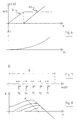
- the figure 7 shows a diagram that shows the positioning of the poles/zeros in the frequencies plane, particularly it is possible to note the uniform spacing between the couples of poles/zeros along a logarithmic frequency axle inside the band B of the working frequencies of the filter. Besides it is possible to note the displacement direction that the poles and the zeros effect at the varying (at the increasing) of the line attenuation, in response of the variations of the bias current to the terminals Pc1-Pcn. Particularly the poles move toward the high frequency and the zeros move toward the low frequency. Besides the couples of poles/zeros move in succession (in the indicated direction) beginning from the identifying number 71 up to the number 75, finally it is increased the filter continuous gain making the opportune bias currents vary.
- figure 8 is shown a diagram of the transfer function of the filter 1 in function of the frequency at the varying of the line attenuation, the arrow points out as varies the transfer function at the increasing of the line attenuation.
- a schematic circuit of an example of a bias generator 8 dependent from the process, shown in figure 9, comprises a plurality of transistors 61 and 62 with n channel having the source connected to ground, the drains respectively connected to the terminals Pr1-Prm, and the gate connected together and connected to a node at which terminals are connected a gate of a transistor 63, a terminal of a generator of current Iref 67 and a branch of a first current mirror 68.
- the source of the transistor 63 is connected to ground and the drain is connected to the source of a differential couple formed by the transistors 64 and 65 with channel n which gates are respectively connected to two reference voltages Vref1 and Vref2, with Vref2>Vref1, and the drains are connected to a second current mirror 66 connected to the power supply Vcc.
- the drain of the transistor 64 is also connected to a branch of the mirror 68. This circuit generates currents able to compensate the variations in temperature, of the supply voltage and of the dispersions of the characteristics (from device to device) due to the construction process.
Landscapes
- Engineering & Computer Science (AREA)
- Computer Networks & Wireless Communication (AREA)
- Signal Processing (AREA)
- Networks Using Active Elements (AREA)
Abstract
Description
- The present invention refers to a method to equalise signals transmitted on a line as well as an equaliser filter realised in CMOS technology and besides an integrated circuit comprising an equaliser circuit.
- In high speed line communications, for instance in the case of data transmission of SDH equipments, the only filtration of the received signal is not sufficient to recover the data with a small error rate. An equaliser circuit is therefore necessary to compensate the line loss and improve the intersymbol interferences of the datum to recover. As known the line dispersion losses are linearly proportional to the length of the line and besides they are proportional to the square root of the frequency of transmission. The equaliser must therefore have a frequency response inversely proportional to that of the line. Particularly it is necessary an adaptive equaliser able to deal with variable lengths of line without altering signifyingly the intersymbol interferences.
- Object of the present invention is that to realise an equaliser able to compensate the line attenuations in a simple and effective way.
- In accordance with the present invention, such an object is reached by means of a method to equalise signals transmitted on a line comprising the following phases: applying an analogical adaptive filter in series to said line, having a working frequency band and having at least one pole and at least one zero the position of which in said working frequency band is variable in response to the attenuation of said line; applying a retroaction circuit to the output of said filter able to vary the position of said at least one pole and at least one zero; characterised by setting said at least one pole and at least one zero in correspondence to a prefixed frequency of said working frequency band; moving the position of said at least one pole toward the high frequencies at the increasing of said attenuation of said line; moving the position of said at least one zero toward the low frequencies at the increasing of said attenuation of said line.
- Such object is also reached by means of an equaliser circuit of signals transmitted on a line having an attenuation comprising: an analogical adaptive filter applied in series to said line comprising at least two transconductance filters having a bias current each and to which it is associated at least one pole and at least one zero the position in frequency of which in the working band is variable in response to said bias current; a retroaction circuit applied to the output of said filter able to vary said bias current; said bias current varies at the varying of said attenuation of said line; characterised in that said at least two transconductance filters have said bias current of prefixed value; said bias current is made to vary at the increasing of said attenuation so that said at least one pole is moved toward the high frequencies; said bias current is made to vary at the increasing of said attenuation so that said at least a zero is moved toward the low frequencies.
- Such an object is further on reached by means of an integrated circuit of CMOS type comprising an equaliser filter of signals transmitted on a line in accordance to what said above.
- Thanks to the present invention it is possible to realise a linear equaliser that does not require of any external regulation. It results to be very simple as the retroaction loop checks only the output voltage. Besides realising it completely in CMOS technology it is possible to integrate it with other circuits on a single chip.
- The characteristics and the advantages of the present invention will result evident from the following detailed description of one of its embodiment, illustrated as example not limitative in the joined sketches, in which:
- the figure 1 shows a blocks scheme of the equaliser in accordance to the present invention;
- the figure 2a shows a schematic circuit of an example of a transconductance filter and the figure 2b its Bode diagram;
- the figure 3 shows a schematic circuit of an example of a
circuit 4 that provides an indication of the variation of the line attenuation; - the figure 4 shows a schematic circuit of an example of the circuit of
charge pump 5; - the figure 5 shows a schematic circuit of an example of a
variable bias generator 7; - the figure 6 shows a diagram that shows the course of the voltage to the
terminal of the
capacitor 6 and the course of the control current of theadaptive filter 1; - the figure 7 shows a diagram that shows the positioning and the variations of the poles/zeros in the frequencies plane;
- the figure 8 shows a diagram that shows the course of the transfer
function of the
filter 1 in the frequency at the varying of the line attenuation; - the figure 9 shows a schematic circuit of a
bias generator 8 dependent on the process. -
- A block scheme of an equaliser in accordance to the present invention, shown in figure 1, comprises an
input signal 10, coming from a line, applied to anadaptive filter 1 which provides anoutput 11. The signal at the output of theadaptive filter 1 is applied to acomparator 3 that compares thissignal 11 with areference voltage 13. At the output of thecomparator 3 there is afilter 14 composed of afirst circuit 4 that provides an indication of the variation of the line attenuation, connected to acharge pump 5 which in turn is connected to acapacitor 6. Thecircuit 4 is sampled by a workingfrequency 15. The voltage at the terminals of thecapacitor 6 is applied to avariable bias generator 7. To thegenerator 7 are applied, preferably, also the signals Pr1-Prm coming from abias generator 8 dependent on the process. The signals Pc1-Pcn in output from thegenerator 7 are applied to theadaptive filter 1. - The
filter 1 comprises preferably adaptive filters of the transconductance type with biquadratic cells, for instance in figure 2a is drawn the block scheme of a transconductance filter having one pole which has aninput 20 and it comprises afirst stage 21 having transconductance Gm, and asecond stage 22 having transconductance GmD, anoutput 23. Between thefirst stage 21 and the second stage is connected a capacitor C. To thefirst stage 21 is connected a terminal Pc1 and to thesecond stage 22 is connected a terminal Pc2, which receives the bias current. The bias current Pc2 makes vary the GmD transconductance of the circuit which makes vary the position of the pole in frequency in the working band accordingly. In fact it could be seen from the figure2b, where it is represented the Bode diagram of the circuit of figure 2a, that the position of the pole in frequency is given by the division GmD/C and the point in which the gain module is equal to 1 it is equal to Gm/C. Therefore making the bias current Pc2 to vary, varies the value of GmD and therefore the pole frequency position. The bias current Pc1 makes vary the Gm transconductance of the circuit which, if it is made to vary in a separate way as regards the current Pc2, it makes vary the continuous gain accordingly, which as it could be seen in the figure 2b it is equal to Gm/GmD. If the bias current Pc1 and Pc2 have been made to vary of the same quantity the pole position moves but the continuous gain does not vary. - To each filter of this type could be associated either one pole or one zero in accordance to the particular type of circuit. To be able to make vary the position of each pole and of each zero it is necessary a bias current for each of them and a current to make vary (increase) the continuous gain of a prefixed value. In an example of realisation of the present invention, the
filter 1 comprises two biquadratic filters and one at a single stage, for a total of 5 poles and of 5 zeros. Such types of filters are well known by the skilled in the art, and they are not furtherly described, an example of such filters could be found in the article of F. Rezzi, I. Bietti, M. Cazzaniga and R. Castello by the title "A 70 mW seventh order filter with 7-50 MHz cut-off frequency and programmable boost and group delay equalization" published in the IEEE Journal of solid state circuits, vol. 32, No. 12, December 1997. - The signals Pc1-Pcn correspond to the bias current (variable at the varying of the line attenuation) of the transconductance filters; preferably these bias currents are compensated by the Pr1-Prm signals that correspond to the currents supplied by the
bias generator 8 which depend on the thermal and constructive variations of the device. - A schematic circuit of an example of a
circuit 4 that supplies an indication of the variation of the line attenuation, shown in figure 3, comprises a firstbistabile circuit 31 of D type and a secondbistabile circuit 32 of D type. The output of thecomparator 3 is applied to aterminal 35 of the firstbistabile circuit 31 which corresponds to the reset input R of the circuit and also to an input of aNOR circuit 33, the output Q of which is connected to the input D of the bistabile 31. The output Q of thebistabile 31 is applied the input D of the secondbistabile circuit 32, the output Q of which is applied to theoutput terminal 36. The output Q of thebistabile 31 is also applied to the second input of theNOR circuit 33. A clock signal is applied to theterminal 15 that it is connected to the clock input of the bistabile 32 and it is also connected to the clock input of the bistabile 31 through aninverter circuit 34. - A schematic circuit of an example of the
charge pump circuit 5, shown in figure 4, comprises afirst transistor 41 with p channel and asecond transistor 42 with n channel having the gates connected together in order to form an input terminal 36 (connected to the output of the circuit 4), the source of thetransistor 41 is connected to the supply voltage, thetransistor source 42 is connected to ground, the drain of thetransistor 42 is connected to the drain of thetransistor 41 and they are connected to aterminal 44 of thecapacitor 6, the other terminal of thecapacitor 6 is set to ground. If theinput signal 36 of thecharge pump circuit 5 is at high level, thecapacitor 6 discharge itself, if the signal is at a low level thecapacitor 6 charge itself. - The whole of the
circuits filter 14 that integrates the signal in output from thecomparator 3 and it provides in output a signal proportional to the course of the line attenuation that is used to predispose the bias and control current Pc1-Pcn of thefilter 1. - Particularly the
circuit 4, drawn in figure 3 provides in output a signal for instance of high level if the signal in output from thecomparator 3 is remained high for at least one clock cycle of theworking frequency 15. Varying theworking frequency 15 it is possible to vary the reaction times of the circuit at the varying of the line attenuation. Thecharge pump 5, charges and discharges thecapacitor 6 so that to its terminals it is present a voltage proportional to the value of line attenuation opportunely filtered. A schematic circuit of an example of avariable bias generator 7, shown in figure 5, comprises aterminal 44 to which it has been applied the voltage present on thecapacitor 6, connected to the gate of atransistor 45 with n channel, the source is connected to ground and the drain is connected to a branch of a firstcurrent mirror 46 which is connected to the supply voltage Vcc through atransistor 47 with p channel. The other branch of thecurrent mirror 46 is connected to a branch of a secondcurrent mirror 48, in the other branch of themirror 48 flows a current Ic1 and corresponds to the terminal Pc1. The drain of thetransistor 45 is connected also to the source of thetransistor 49 with p channel. The drain of thetransistor 49 is connected to a branch of a thirdcurrent mirror 50 which is connected directly to the supply voltage Vcc. The other branch of thecurrent mirror 50 is connected to a branch of a fourthcurrent mirror 51, in the other branch of themirror 51 flows a current Ic2 and corresponds to the terminal Pc2. The gate of thetransistor 49 is connected to the drain of atransistor 53 having the source connected to ground and the gate applied the terminal Pr1. The gate of thetransistor 49 is also connected to thetransistor 52 with p channel connected like a diode and applied to the supply voltage Vcc that forms a current mirror together with thetransistor 47 the two gates of which are connected together. - In figure 5, only for representation simplicity have been drawn only the circuits that provide current to the 2 terminal Pc1 and Pc2 of the
filter 1 depending on the value of the input Vc of thecapacitor 6 and of the input Pr1 coming from thebias generator 8. Also in this case it has been considered for representation simplicity only one terminal of the plurality of the terminals Pr1-Prm. - The
variable bias generator 7 must provide the bias currents by the terminals Pc1-Pcn to the various transconductance filters present in thefilter 1. Such bias currents must be placed at quiescent (Vc= 0), for instance placed for a line having length equal to 0 and they therefore must vary at the varying of the line attenuation. Thegenerator 7 receives in input the Vc signal from thecapacitor 6 and it is able to absorb the current Ic1 (from the terminal Pc1), which starting from Vc equal to null, linearly increases at the increasing of Vc, up to reach a limit of current equal to Ip/2, where Ip is the flowing current in thetransistor 53, after that it begins to increase linearly the current Ic2, (up to to a possible circuital limit). The current Ip could be generated by a fixed generator Ip but, the equaliser circuit comprises besides preferably thebias generator 8 which provides a bias current able to compensate the thermal and constructive variations of the equaliser. For instance at the increasing of the temperature the current Ip increases according to the variation of the bias present on the terminal Pr1. - In figure 6 could be seen the waveforms of some signals of the circuit of figure 5. Particularly it is possible to see the exponential relationship between the input voltage Vc applied to the
terminal 44 of thetransistor 45 and its relative drain current Ic. Moreover it is possible to see the course of the current Ic1 and Ic2 flowing respectively in themirrors - As already said it has been represented for simplicity a reduced circuit able to provide only two currents to the terminals Pc1 and Pc2. It is however to imagine a series of currents one for each pole and one for each zero present in the
filter 1 and besides the current or preferably the currents necessary to increase the continuous gain. The currents relative to each couple of poles/ zeros, positioned in frequency in the same place, will have a similar course as, better explained further on, they will have to move simultaneously, after that the couple of poles/zeros placed immediately at a smaller frequency will move. - The figure 7 shows a diagram that shows the positioning of the poles/zeros in the frequencies plane, particularly it is possible to note the uniform spacing between the couples of poles/zeros along a logarithmic frequency axle inside the band B of the working frequencies of the filter. Besides it is possible to note the displacement direction that the poles and the zeros effect at the varying (at the increasing) of the line attenuation, in response of the variations of the bias current to the terminals Pc1-Pcn. Particularly the poles move toward the high frequency and the zeros move toward the low frequency. Besides the couples of poles/zeros move in succession (in the indicated direction) beginning from the identifying
number 71 up to thenumber 75, finally it is increased the filter continuous gain making the opportune bias currents vary. In practice first moves the pole and the zero of thecouple 71 placed at high frequency inside the working band, therefore in succession moves the pole and the zero of thecouple 72 placed to a lower frequency as regards thecouple 71 that has been moved previously up to the movement of thecouple 75 placed at a lower frequency. Therefore, when all the couples have moved it is increased the continuous gain. All the displacement above reported are effected in consequence of the variations of the bias and control current present on the terminals Pc1-Pcn. - In figure 8 is shown a diagram of the transfer function of the
filter 1 in function of the frequency at the varying of the line attenuation, the arrow points out as varies the transfer function at the increasing of the line attenuation. At the moving of the couples of poles/zeros above mentioned it is possible to see in figure 8 the variation of the transfer function and particularly it is possible to see that only at the end the continuous gain is varied. - A schematic circuit of an example of a
bias generator 8 dependent from the process, shown in figure 9, comprises a plurality oftransistors transistor 63, a terminal of a generator ofcurrent Iref 67 and a branch of a firstcurrent mirror 68. The source of thetransistor 63 is connected to ground and the drain is connected to the source of a differential couple formed by thetransistors current mirror 66 connected to the power supply Vcc. The drain of thetransistor 64 is also connected to a branch of themirror 68. This circuit generates currents able to compensate the variations in temperature, of the supply voltage and of the dispersions of the characteristics (from device to device) due to the construction process. - In accordance to the present invention it is possible to realise a device in CMOS technology at low cost with the possibility of being integrated with other circuits on the same chip where external circuits are not required. Besides a good equalizzation with a reduced number of poles and zeros is obtained, in fact with 5 poles and 5 zeros and an equalisation band of 260 MHz it is possible to equalize signals transmitted on a line of length of about 350 m.
Claims (12)
- Method to equalise signals transmitted on a line comprising the following phases: applying an analogical adaptive filter in series to said line, having a working frequency band and having at least one pole and at least one zero the position of which in said working frequency band is variable in response to the attenuation of said line; applying a retroaction circuit to the output of said filter able to vary the position of said at least one pole and at least one zero; characterised by setting said at least one pole and at least one zero in correspondence to a prefixed frequency of said working frequency band; moving the position of said at least one pole toward the high frequencies at the-increasing of said attenuation of said line; moving the position of said at least one zero toward the low frequencies at the increasing of said attenuation of said line.
- Method in accordance to the claim 1 characterized by positioning a first couple of poles/zeros of said analogical adaptive filter to a first prefixed frequency in said working frequency band;positioning a second couple of poles/zeros of said analogical adaptive filter to a second prefixed frequency in said working frequency band;said first prefixed frequency is greater than said second prefixed frequency;spacing said first and second prefixed frequency in a logarithmic way in said working frequency band;moving the poles of said first and second couple of poles/zeros toward the high frequencies at the increasing of said attenuation of said line;moving the zero of said first and second couple of poles/zeros toward the low frequencies to the increasing of said attenuation of said line.
- Method in accordance to the claim 2 characterized by moving the position of the first couple of pole/zero and therefore in succession the position of the second couple of pole/zero at the increasing of said attenuation of said line.
- Method in accordance to the claim 1 characterized in that said at least one pole and at least a zero are placed in the frequencies plane in correspondence of said prefixed frequency in order to equalize the attenuation of said line when said line has null attenuation.
- Method in accordance to the claim 1 characterized in that said at least one pole and said at least a zero are moved of the 30% compared to the initial position.
- Method in accordance to the claim 1 characterized in that at the increasing of said attenuation of said line after the moving phases of the position of said at least one pole and of said at least a zero comprises the phase of increasing the continuous gain of said adaptive filter.
- Method in accordance to the claim 1 characterized in that said retroaction circuit includes a compensation circuit of the thermal and constructive variations of said equalizer.
- Equaliser circuit of signals transmitted on a line having an attenuation comprising: an analogical adaptive filter (1) applied in series to said line comprising at least two transconductance filters having a bias current (Pc1-Pcn) each and to which it is associated at least one pole and at least one zero the position in frequency of which in the working band (B) is variable in response to said bias current (Pc1-Pcn); a retroaction circuit (3, 4, 5, 6, 7) applied to the output of said filter (1) able to vary said bias current (Pc1-Pcn); said bias current (Pc1-Pcn) varies at the varying of said attenuation of said line; characterised in that said at least two transconductance filters have said bias current of prefixed value; said bias current is made to vary at the increasing of said attenuation so that said at least one pole is moved toward the high frequencies; said bias current is made to vary at the increasing of said attenuation so that said at least a zero is moved toward the low frequencies.
- Equalizer filter in accordance to the claim 8 characterized in that said adaptative analogical filter (1) includes four transconduttance filters having at least a bias current each and to which are associated two couples of poles and of zeros the position of which in frequency in the working band (B) is variable in response to said bias current;said two couples of poles/zeros are placed having a logarithmic spacing in said working frequency band (B);said bias current is made to vary so that said poles are moved toward the high frequencies at the increasing of said attenuation of said line;said bias current is made to vary so that said zeros are moved toward the low frequencies at the increasing of said attenuation of said line.
- Equalizer filter in accordance to the claim 8 characterized by comprising a bias generating circuit (8) able to modify said bias current in response to the temperature variations.
- Equalizer filter in accordance to the claim 8 characterized in that it has been realized in CMOS technology.
- Integrated circuit of CMOS type comprising an equalizer circuit of signals transmitted on a line in accordance to the claim 8.
Priority Applications (3)
| Application Number | Priority Date | Filing Date | Title |
|---|---|---|---|
| DE60025584T DE60025584D1 (en) | 2000-05-12 | 2000-05-12 | equalizer |
| EP00830343A EP1154586B1 (en) | 2000-05-12 | 2000-05-12 | Equaliser |
| US09/853,315 US7154945B2 (en) | 2000-05-12 | 2001-05-10 | Equalizer |
Applications Claiming Priority (1)
| Application Number | Priority Date | Filing Date | Title |
|---|---|---|---|
| EP00830343A EP1154586B1 (en) | 2000-05-12 | 2000-05-12 | Equaliser |
Publications (2)
| Publication Number | Publication Date |
|---|---|
| EP1154586A1 true EP1154586A1 (en) | 2001-11-14 |
| EP1154586B1 EP1154586B1 (en) | 2006-01-18 |
Family
ID=8175324
Family Applications (1)
| Application Number | Title | Priority Date | Filing Date |
|---|---|---|---|
| EP00830343A Expired - Lifetime EP1154586B1 (en) | 2000-05-12 | 2000-05-12 | Equaliser |
Country Status (3)
| Country | Link |
|---|---|
| US (1) | US7154945B2 (en) |
| EP (1) | EP1154586B1 (en) |
| DE (1) | DE60025584D1 (en) |
Cited By (1)
| Publication number | Priority date | Publication date | Assignee | Title |
|---|---|---|---|---|
| FR2940555A1 (en) * | 2008-12-19 | 2010-06-25 | Thales Sa | Self-calibrating filtering device for global positioning system signal receiver, has latch to control current control device that controls current supply of filter to minimize difference between output signal phase and another signal phase |
Families Citing this family (8)
| Publication number | Priority date | Publication date | Assignee | Title |
|---|---|---|---|---|
| US7447261B2 (en) * | 2003-07-08 | 2008-11-04 | Conexant Systems, Inc. | Adaptive frequency equalizer |
| US7610022B1 (en) * | 2003-10-29 | 2009-10-27 | Marvell International Ltd. | Filter circuit with negative transconductance |
| US20060245485A1 (en) * | 2005-04-28 | 2006-11-02 | Intel Corporation | Continuous-time equalizer |
| US8031763B2 (en) * | 2006-12-28 | 2011-10-04 | Intel Corporation | Automatic tuning circuit for a continuous-time equalizer |
| US7880568B2 (en) * | 2007-09-17 | 2011-02-01 | Oracle America, Inc. | Equalizer system having a tunable active inductor |
| US7888910B2 (en) * | 2007-11-29 | 2011-02-15 | Hdm Systems Corporation | Sequencing switched single capacitor for automatic equalization of batteries connected in series |
| US8989214B2 (en) | 2007-12-17 | 2015-03-24 | Altera Corporation | High-speed serial data signal receiver circuitry |
| US8761237B2 (en) | 2011-11-03 | 2014-06-24 | Lsi Corporation | Low nonlinear distortion variable gain amplifier |
Citations (3)
| Publication number | Priority date | Publication date | Assignee | Title |
|---|---|---|---|---|
| US4273963A (en) * | 1979-05-25 | 1981-06-16 | Bell Telephone Laboratories, Incorporated | Automatic equalization for digital transmission systems |
| US5257286A (en) * | 1990-11-13 | 1993-10-26 | Level One Communications, Inc. | High frequency receive equalizer |
| US5805031A (en) * | 1996-09-03 | 1998-09-08 | Advanced Micro Devices, Inc. | Transistor ratio controlled CMOS transmission line equalizer |
Family Cites Families (4)
| Publication number | Priority date | Publication date | Assignee | Title |
|---|---|---|---|---|
| US5699022A (en) * | 1996-02-09 | 1997-12-16 | Dsc Communications Corporation | Adaptive cable equalizer |
| US5978417A (en) * | 1996-02-23 | 1999-11-02 | National Semiconductor Corporation | Adaptive cable equalizer |
| US5940441A (en) * | 1996-10-29 | 1999-08-17 | International Business Machines Corporation | Integrated adaptive cable equalizer using a continuous-time filter |
| US6240131B1 (en) * | 1997-06-30 | 2001-05-29 | Advanced Micro Devices, Inc. | Digitally controlled transmission line equalizer |
-
2000
- 2000-05-12 DE DE60025584T patent/DE60025584D1/en not_active Expired - Lifetime
- 2000-05-12 EP EP00830343A patent/EP1154586B1/en not_active Expired - Lifetime
-
2001
- 2001-05-10 US US09/853,315 patent/US7154945B2/en not_active Expired - Fee Related
Patent Citations (3)
| Publication number | Priority date | Publication date | Assignee | Title |
|---|---|---|---|---|
| US4273963A (en) * | 1979-05-25 | 1981-06-16 | Bell Telephone Laboratories, Incorporated | Automatic equalization for digital transmission systems |
| US5257286A (en) * | 1990-11-13 | 1993-10-26 | Level One Communications, Inc. | High frequency receive equalizer |
| US5805031A (en) * | 1996-09-03 | 1998-09-08 | Advanced Micro Devices, Inc. | Transistor ratio controlled CMOS transmission line equalizer |
Cited By (1)
| Publication number | Priority date | Publication date | Assignee | Title |
|---|---|---|---|---|
| FR2940555A1 (en) * | 2008-12-19 | 2010-06-25 | Thales Sa | Self-calibrating filtering device for global positioning system signal receiver, has latch to control current control device that controls current supply of filter to minimize difference between output signal phase and another signal phase |
Also Published As
| Publication number | Publication date |
|---|---|
| EP1154586B1 (en) | 2006-01-18 |
| US20010040921A1 (en) | 2001-11-15 |
| DE60025584D1 (en) | 2006-04-06 |
| US7154945B2 (en) | 2006-12-26 |
Similar Documents
| Publication | Publication Date | Title |
|---|---|---|
| US6169764B1 (en) | Analog adaptive line equalizer | |
| US5257286A (en) | High frequency receive equalizer | |
| US6084465A (en) | Method for time constant tuning of gm-C filters | |
| US4135132A (en) | Passive filter compensation network | |
| US10075141B1 (en) | Continuous time linear equalizer with two adaptive zero frequency locations | |
| KR100323656B1 (en) | Variable Light Amplifier | |
| US8117249B1 (en) | Equalizer systems and methods utilizing analog delay elements | |
| Babanezhad | A 3.3 V analog adaptive line-equalizer for fast ethernet data communication | |
| EP1154586B1 (en) | Equaliser | |
| JPH09331363A (en) | Transmission line loss equalization circuit | |
| JP3431077B2 (en) | Line driver with adaptive output impedance | |
| JPH04282912A (en) | Continuous time filter tuned circuit and method | |
| US5940441A (en) | Integrated adaptive cable equalizer using a continuous-time filter | |
| US6111467A (en) | Circuit for time constant tuning of gm-C filters | |
| EP0204088A2 (en) | Integrated circuit with a phase-locked loop | |
| US20060140262A1 (en) | Low voltage multistage adaptive equalizer | |
| US6069522A (en) | Circuitry and method for providing boost and asymmetry in a continuous-time filter | |
| US4731590A (en) | Circuits with multiple controlled gain elements | |
| JP2003249831A (en) | Optical receiving circuit | |
| US6316927B1 (en) | Voltage output driver and filter | |
| US6958652B2 (en) | Transconductance varying circuit of transconductor circuit, varying bandwidth filter circuit using the same and digital tuning circuit of transconductor-capacitor filter | |
| US7202748B2 (en) | Ultra-wideband constant gain CMOS amplifier | |
| EP0687398B1 (en) | Receive side pulse width controlled adaptive equalizer | |
| US4229716A (en) | Amplitude equalizer circuit | |
| US4417214A (en) | Monolithic IC general purpose active filter |
Legal Events
| Date | Code | Title | Description |
|---|---|---|---|
| PUAI | Public reference made under article 153(3) epc to a published international application that has entered the european phase |
Free format text: ORIGINAL CODE: 0009012 |
|
| AK | Designated contracting states |
Kind code of ref document: A1 Designated state(s): AT BE CH CY DE DK ES FI FR GB GR IE IT LI LU MC NL PT SE Kind code of ref document: A1 Designated state(s): DE FR GB IT |
|
| AX | Request for extension of the european patent |
Free format text: AL;LT;LV;MK;RO;SI |
|
| 17P | Request for examination filed |
Effective date: 20020503 |
|
| AKX | Designation fees paid |
Free format text: DE FR GB IT |
|
| 17Q | First examination report despatched |
Effective date: 20040427 |
|
| GRAP | Despatch of communication of intention to grant a patent |
Free format text: ORIGINAL CODE: EPIDOSNIGR1 |
|
| GRAS | Grant fee paid |
Free format text: ORIGINAL CODE: EPIDOSNIGR3 |
|
| GRAA | (expected) grant |
Free format text: ORIGINAL CODE: 0009210 |
|
| AK | Designated contracting states |
Kind code of ref document: B1 Designated state(s): DE FR GB IT |
|
| REG | Reference to a national code |
Ref country code: GB Ref legal event code: FG4D |
|
| REF | Corresponds to: |
Ref document number: 60025584 Country of ref document: DE Date of ref document: 20060406 Kind code of ref document: P |
|
| PG25 | Lapsed in a contracting state [announced via postgrant information from national office to epo] |
Ref country code: DE Free format text: LAPSE BECAUSE OF FAILURE TO SUBMIT A TRANSLATION OF THE DESCRIPTION OR TO PAY THE FEE WITHIN THE PRESCRIBED TIME-LIMIT Effective date: 20060419 |
|
| PG25 | Lapsed in a contracting state [announced via postgrant information from national office to epo] |
Ref country code: GB Free format text: LAPSE BECAUSE OF NON-PAYMENT OF DUE FEES Effective date: 20060512 |
|
| ET | Fr: translation filed | ||
| PLBE | No opposition filed within time limit |
Free format text: ORIGINAL CODE: 0009261 |
|
| STAA | Information on the status of an ep patent application or granted ep patent |
Free format text: STATUS: NO OPPOSITION FILED WITHIN TIME LIMIT |
|
| 26N | No opposition filed |
Effective date: 20061019 |
|
| GBPC | Gb: european patent ceased through non-payment of renewal fee |
Effective date: 20060512 |
|
| PGFP | Annual fee paid to national office [announced via postgrant information from national office to epo] |
Ref country code: IT Payment date: 20070524 Year of fee payment: 8 |
|
| PGFP | Annual fee paid to national office [announced via postgrant information from national office to epo] |
Ref country code: FR Payment date: 20070529 Year of fee payment: 8 |
|
| REG | Reference to a national code |
Ref country code: FR Ref legal event code: ST Effective date: 20090119 |
|
| PG25 | Lapsed in a contracting state [announced via postgrant information from national office to epo] |
Ref country code: FR Free format text: LAPSE BECAUSE OF NON-PAYMENT OF DUE FEES Effective date: 20080602 |
|
| PG25 | Lapsed in a contracting state [announced via postgrant information from national office to epo] |
Ref country code: IT Free format text: LAPSE BECAUSE OF NON-PAYMENT OF DUE FEES Effective date: 20080512 |