EP1154453A2 - Armature spring for a relay - Google Patents
Armature spring for a relay Download PDFInfo
- Publication number
- EP1154453A2 EP1154453A2 EP01110814A EP01110814A EP1154453A2 EP 1154453 A2 EP1154453 A2 EP 1154453A2 EP 01110814 A EP01110814 A EP 01110814A EP 01110814 A EP01110814 A EP 01110814A EP 1154453 A2 EP1154453 A2 EP 1154453A2
- Authority
- EP
- European Patent Office
- Prior art keywords
- spring
- armature
- section
- lever
- torsion
- Prior art date
- Legal status (The legal status is an assumption and is not a legal conclusion. Google has not performed a legal analysis and makes no representation as to the accuracy of the status listed.)
- Granted
Links
Images

Classifications
-
- H—ELECTRICITY
- H01—ELECTRIC ELEMENTS
- H01H—ELECTRIC SWITCHES; RELAYS; SELECTORS; EMERGENCY PROTECTIVE DEVICES
- H01H50/00—Details of electromagnetic relays
- H01H50/16—Magnetic circuit arrangements
- H01H50/18—Movable parts of magnetic circuits, e.g. armature
- H01H50/24—Parts rotatable or rockable outside coil
Definitions
- the present invention relates to an armature spring for a relay having a fastening section with which the armature spring can be fastened to an armature or a thrust bearing, an oblong spring section which is connected at a first end with the fastening section, as well as a lever adjacent to the spring section and comprising a support area for supporting the lever on a thrust bearing or an armature.
- Armature springs generally accomplish several tasks. The armature into an open position and they urge the armature against an armature bearing, so that an armature pivot axis is achieved. They can also ensure that an opening force can be exerted with a contact pair connected to the armature via a contact spring.
- EP 0707331 A1 describes an armature spring of the aforementioned type, arranged in the form of a beam fixed at both ends.
- the middle of the beam comprises a projection which engages into a recess of an armature.
- the armature spring and the recess in the armature are thereby positioned such that the armature is biased into an open position.
- the armature spring is subject to bending stress.
- An arrangement of this type is not suitable for armatures with a high rotary angle. Furthermore, the restoring force of this known armature spring is minimal and in many cases insufficient.
- torsion springs are known as armature springs having spiral torsion springs. These known springs present the disadvantage that they require significant construction space, with nonetheless the area next to the spring remaining unused, contradicting efforts to achieve miniturization and a compact design.
- an armature spring of the aforementioned type characterised in that the support area and the fastening sections are located on opposite sides of the longitudinal axis of the spring section such that during movement of the armature, the spring section is subject primarily to torsional stress.
- armature springs obtain the required force not through elastic bending strain but through torsion. Due to the fact that the support area is located on the longitudinal axis side of the spring section opposite the fastening sections, the amount of bending stress during the stressing of the spring section is significantly reduced and the amount of transverse stress (torsion) is significantly elevated.
- the advantage of the torsionally stressed spring section is that the stress is evenly distributed over the length of the spring section. This means that, despite high force and low spring rates, mechanical tensions can be kept relatively low. This in turn enables the armature spring to be designed in geometric dimensions which are smaller than in traditional springs. Due to this solution, the existing construction space of a preset geometry can be optimally used. In the case of a preset maximum available construction space, particularly high armature restoring forces can thus be realised.
- An embodiment combines bending strain and torsion, either through a flexible design of the lever or through increasing the amount of bending strain.
- the combination of bending strain and torsion results in the availability of several parameters according to which the desired spring characteristic can be adjusted to meet requirements.
- the spring section may possess the form of a torsion web, whereby the width of the torsion web corresponds to approximately the material thickness. Both ends of the torsion web are firmly connected with the armature and the lever is arranged in the middle of the torsion web. Due to the form and arrangement of the lever or the thrust bearing, the force generated by the armature spring can be optimally divided into bias force and armature bearing force.
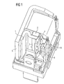
- Figure 1 shows a relay comprising an armature 1 with a rotary angle of approximately 12°.
- the armature pivot axis is thereby located on a pole face of a core 2.
- the armature 1 is positioned on the pole face, but can however still be shifted without additional measures.
- An armature spring 4 is attached to the side of the armature 1 opposite the pole face by means of a fastening section 3.
- the armature spring 4 is bent off on one edge of the armature 1, subsequently extending along the narrow edge of the armature 1 and making contact with the core 2 close to the armature pivot axis.
- the armature spring 4 is adjacent to the armature 1 as well as the core 2, so that the armature 1 cannot slip in the direction of a yoke 5 forming a second pole face.
- the armature spring 4 is formed in such a way that the fastening section 3 extends along the entire width of the armature 1.
- a torsion web 6 extends between the ends of the legs 5a and 5b of the armature spring 4.
- the torsion web 6 extends essentially parallel to the armature pivot axis.
- a lever 7 is arranged, which is supported at its free end on a thrust bearing 8. The force transmission thus passes from the thrust bearing 8 via the lever 7, the torsion web 6 and the legs 5a and 5b of the armature spring 4 to the armature 1.
- Figure 2 shows the armature spring 4 so that the entire lever 7 can be seen.
- the lever 7 is not rigid, but a flexible deformable element.
- the spring force of the armature spring 4 can thus be composed of two components, the tension of the torsion web 6 and the bending spring force of the lever 7.
- the degree of bending strain and torsion can be freely chosen so that the desired spring characteristic can be easily adjusted in accordance with requirements.
- the geometric shape of the lever 7 is selected so that the force can be transmitted from the thrust bearing 8 to the torsion web 6 in such a manner that the remaining bending stress on the torsion web 6 is as low as possible. Bending of the torsion web 6 is to be avoided as it is intended to be subject to torsion, not bending.
- the torsion web 7 is nevertheless strained with a bending force, this rapidly leads to excessive loading of the torsion web. If the latter is strained only with one torsion, the torsion web can have a very narrow design.
- the width of the torsion web 6 corresponds to approximately the thickness of the material. If a bending stress is unavoidable or the torsion web 6 is to be protected against such, the possibility exists of significantly increasing the flexural strength by means of a bending edge in the longitudinal direction of the web 6, without any significant deterioration of the torsion characteristics.
- an armature spring according to the invention has particular advantages, especially if an even spring characteristic curve is desired.
- An even spring characteristic curve can typically be achieved through the spring being very long and/or very thin.
- a great length is of a disadvantage once again when considering space economy; an extremely thin leaf spring on the other hand exhibits unfavorable mechanical properties.
- torsion springs have the advantage that the stress is evenly distributed over the entire length of the torsion web 6, in addition to achieving a sufficiently even characteristic curve.
- a torsion spring as armature spring has the advantage in this case that the force progression is generally linear and exhibits a comparatively low build-up, whereas in the case of a leaf spring the force progression exhibits a relatively high build-up.
- Figure 3 shows a cross section of the relay.
- the fastening of the armature spring 4 to the armature 1 is particularly easily recognisable.
- it shows clearly how the position of the armature 1 on the core 2 is determined by the armature spring 4.
- the armature 1 is inclined to the armature side adjacent to the armature pivot axis so that in the closed state of the armature 1 a wedge-shaped gap remains between the armature spring 4 and the core.
- the armature 1 can freely pivot into the opened position, without the armature spring 4 abutting the side face of the core 2.
- the armature 1 is nevertheless safeguarded against slipping in the direction of the yoke 5.
Landscapes
- Physics & Mathematics (AREA)
- Electromagnetism (AREA)
- Electromagnets (AREA)
Abstract
Description
Claims (8)
- An armature spring for a relay comprisinga fastening section with which the armature spring can be fastened to an armature or a thrust bearing;an oblong spring section which is connected at a first end with the fastening section;a lever adjacent to the spring section and comprising a support area for supporting the lever on a thrust bearing or an armature;the support area and the fastening sections being located on opposite sides of the longitudinal axis of the spring section whereby during movement of the armature, the spring section is subject mainly to torsional stress.
- The armature spring according to claim 1, wherein the lever is flexibly deformable.
- The armature spring according to claim 1, wherein the spring section is formed by a torsion web.
- The armature spring according to claim 3, wherein the width of the torsion web corresponds to the thickness of the material out of which the armature spring is made.
- The armature spring according to claim 3, wherein the torsion web also carries out a bending movement and the torsion web comprises a bending edge extending in a longitudinal direction, whereby the flexural strength of the torsion web is increased.
- The armature spring according to claim 3, characterised in that the lever is attached in the middle of the torsion web, and both ends of the torsion web are connected to the fastening section.
- The armature spring according to claim 1, wherein a spring movement of the support area of the armature spring with relation to the fastening end can be realised with a spring angle of 10° to 15°.
- The armature spring according to claim 1, wherein the fastening section is attached to the armature by welding or riveting.
Priority Applications (1)
| Application Number | Priority Date | Filing Date | Title |
|---|---|---|---|
| EP20010110814 EP1154453B1 (en) | 2000-05-08 | 2001-05-04 | Armature spring for a relay |
Applications Claiming Priority (3)
| Application Number | Priority Date | Filing Date | Title |
|---|---|---|---|
| EP00109694 | 2000-05-08 | ||
| EP00109694 | 2000-05-08 | ||
| EP20010110814 EP1154453B1 (en) | 2000-05-08 | 2001-05-04 | Armature spring for a relay |
Publications (3)
| Publication Number | Publication Date |
|---|---|
| EP1154453A2 true EP1154453A2 (en) | 2001-11-14 |
| EP1154453A3 EP1154453A3 (en) | 2004-01-02 |
| EP1154453B1 EP1154453B1 (en) | 2005-07-27 |
Family
ID=26070908
Family Applications (1)
| Application Number | Title | Priority Date | Filing Date |
|---|---|---|---|
| EP20010110814 Expired - Lifetime EP1154453B1 (en) | 2000-05-08 | 2001-05-04 | Armature spring for a relay |
Country Status (1)
| Country | Link |
|---|---|
| EP (1) | EP1154453B1 (en) |
Family Cites Families (2)
| Publication number | Priority date | Publication date | Assignee | Title |
|---|---|---|---|---|
| US2847620A (en) * | 1954-01-25 | 1958-08-12 | Andrew W Vincent | Electromagnets |
| BE539029A (en) * | 1954-06-18 |
-
2001
- 2001-05-04 EP EP20010110814 patent/EP1154453B1/en not_active Expired - Lifetime
Also Published As
| Publication number | Publication date |
|---|---|
| EP1154453B1 (en) | 2005-07-27 |
| EP1154453A3 (en) | 2004-01-02 |
Similar Documents
| Publication | Publication Date | Title |
|---|---|---|
| DE10005895C2 (en) | Monostable miniature switch | |
| US7221246B2 (en) | Split rotor system and method with springs | |
| US4743877A (en) | Electromagnetic relay | |
| US6323581B1 (en) | Low component count release mechanism | |
| US4956623A (en) | Electromagnetic relay | |
| US6679488B2 (en) | Armature spring for a relay | |
| US9136067B2 (en) | Rotative double contact | |
| EP1154453B1 (en) | Armature spring for a relay | |
| KR100846277B1 (en) | Circuit breaker | |
| US4625194A (en) | A.C. contactor | |
| US5717370A (en) | Electromagnetic switching device, particularly contactor | |
| FI92772C (en) | Leaf spring system and switch with this system | |
| EP0902451A1 (en) | Switching device for connections between electric circuits | |
| EP1286374B1 (en) | Switching relay with improved armature spring | |
| US20040066257A1 (en) | Switching contact arrangement | |
| CN102132063A (en) | Brake | |
| EP1992001A1 (en) | Electrical switch element, particularly a relay, with swivelling lever switch mechanism | |
| EP3051562B1 (en) | Spring Member for an Electric Switching Device such as a Cradle Relay | |
| JP2005216853A (en) | Heavy duty relay | |
| DE102010002305B4 (en) | Thermal overload relay | |
| US5053756A (en) | Electromagnetic relay with return spring | |
| KR102789478B1 (en) | Thermal overload relay | |
| JPS6048852B2 (en) | Electromagnetic contactor actuator drive mechanism | |
| EP1213216A3 (en) | Bending mechanism of rod | |
| JPS60246531A (en) | Electromagnetic contactor |
Legal Events
| Date | Code | Title | Description |
|---|---|---|---|
| PUAI | Public reference made under article 153(3) epc to a published international application that has entered the european phase |
Free format text: ORIGINAL CODE: 0009012 |
|
| AK | Designated contracting states |
Kind code of ref document: A2 Designated state(s): AT BE CH CY DE DK ES FI FR GB GR IE IT LI LU MC NL PT SE TR |
|
| AX | Request for extension of the european patent |
Free format text: AL;LT;LV;MK;RO;SI |
|
| PUAL | Search report despatched |
Free format text: ORIGINAL CODE: 0009013 |
|
| AK | Designated contracting states |
Kind code of ref document: A3 Designated state(s): AT BE CH CY DE DK ES FI FR GB GR IE IT LI LU MC NL PT SE TR |
|
| AX | Request for extension of the european patent |
Extension state: AL LT LV MK RO SI |
|
| 17P | Request for examination filed |
Effective date: 20040525 |
|
| 17Q | First examination report despatched |
Effective date: 20040624 |
|
| AKX | Designation fees paid |
Designated state(s): DE ES FR GB IT |
|
| GRAP | Despatch of communication of intention to grant a patent |
Free format text: ORIGINAL CODE: EPIDOSNIGR1 |
|
| GRAS | Grant fee paid |
Free format text: ORIGINAL CODE: EPIDOSNIGR3 |
|
| GRAA | (expected) grant |
Free format text: ORIGINAL CODE: 0009210 |
|
| AK | Designated contracting states |
Kind code of ref document: B1 Designated state(s): DE ES FR GB IT |
|
| PG25 | Lapsed in a contracting state [announced via postgrant information from national office to epo] |
Ref country code: IT Free format text: LAPSE BECAUSE OF FAILURE TO SUBMIT A TRANSLATION OF THE DESCRIPTION OR TO PAY THE FEE WITHIN THE PRESCRIBED TIME-LIMIT;WARNING: LAPSES OF ITALIAN PATENTS WITH EFFECTIVE DATE BEFORE 2007 MAY HAVE OCCURRED AT ANY TIME BEFORE 2007. THE CORRECT EFFECTIVE DATE MAY BE DIFFERENT FROM THE ONE RECORDED. Effective date: 20050727 |
|
| REG | Reference to a national code |
Ref country code: GB Ref legal event code: FG4D |
|
| REF | Corresponds to: |
Ref document number: 60112169 Country of ref document: DE Date of ref document: 20050901 Kind code of ref document: P |
|
| PG25 | Lapsed in a contracting state [announced via postgrant information from national office to epo] |
Ref country code: ES Free format text: LAPSE BECAUSE OF FAILURE TO SUBMIT A TRANSLATION OF THE DESCRIPTION OR TO PAY THE FEE WITHIN THE PRESCRIBED TIME-LIMIT Effective date: 20051107 |
|
| PLBE | No opposition filed within time limit |
Free format text: ORIGINAL CODE: 0009261 |
|
| STAA | Information on the status of an ep patent application or granted ep patent |
Free format text: STATUS: NO OPPOSITION FILED WITHIN TIME LIMIT |
|
| 26N | No opposition filed |
Effective date: 20060428 |
|
| EN | Fr: translation not filed | ||
| PG25 | Lapsed in a contracting state [announced via postgrant information from national office to epo] |
Ref country code: FR Free format text: LAPSE BECAUSE OF FAILURE TO SUBMIT A TRANSLATION OF THE DESCRIPTION OR TO PAY THE FEE WITHIN THE PRESCRIBED TIME-LIMIT Effective date: 20060922 |
|
| PG25 | Lapsed in a contracting state [announced via postgrant information from national office to epo] |
Ref country code: FR Free format text: LAPSE BECAUSE OF FAILURE TO SUBMIT A TRANSLATION OF THE DESCRIPTION OR TO PAY THE FEE WITHIN THE PRESCRIBED TIME-LIMIT Effective date: 20050727 |
|
| REG | Reference to a national code |
Ref country code: DE Ref legal event code: R081 Ref document number: 60112169 Country of ref document: DE Owner name: TE CONNECTIVITY GERMANY GMBH, DE Free format text: FORMER OWNER: TYCO ELECTRONICS AMP GMBH, 64625 BENSHEIM, DE |
|
| PGFP | Annual fee paid to national office [announced via postgrant information from national office to epo] |
Ref country code: DE Payment date: 20190423 Year of fee payment: 19 |
|
| PGFP | Annual fee paid to national office [announced via postgrant information from national office to epo] |
Ref country code: GB Payment date: 20190501 Year of fee payment: 19 |
|
| REG | Reference to a national code |
Ref country code: DE Ref legal event code: R119 Ref document number: 60112169 Country of ref document: DE |
|
| GBPC | Gb: european patent ceased through non-payment of renewal fee |
Effective date: 20200504 |
|
| PG25 | Lapsed in a contracting state [announced via postgrant information from national office to epo] |
Ref country code: GB Free format text: LAPSE BECAUSE OF NON-PAYMENT OF DUE FEES Effective date: 20200504 |
|
| PG25 | Lapsed in a contracting state [announced via postgrant information from national office to epo] |
Ref country code: DE Free format text: LAPSE BECAUSE OF NON-PAYMENT OF DUE FEES Effective date: 20201201 |