EP1154153A2 - Engine starting method in idling stop condition - Google Patents
Engine starting method in idling stop condition Download PDFInfo
- Publication number
- EP1154153A2 EP1154153A2 EP01110593A EP01110593A EP1154153A2 EP 1154153 A2 EP1154153 A2 EP 1154153A2 EP 01110593 A EP01110593 A EP 01110593A EP 01110593 A EP01110593 A EP 01110593A EP 1154153 A2 EP1154153 A2 EP 1154153A2
- Authority
- EP
- European Patent Office
- Prior art keywords
- pinion
- ring gear
- engine
- starter
- starting
- Prior art date
- Legal status (The legal status is an assumption and is not a legal conclusion. Google has not performed a legal analysis and makes no representation as to the accuracy of the status listed.)
- Granted
Links
- 238000000034 method Methods 0.000 title claims abstract description 30
- 239000007858 starting material Substances 0.000 claims description 108
- 230000035939 shock Effects 0.000 description 19
- 230000000694 effects Effects 0.000 description 6
- 238000010586 diagram Methods 0.000 description 5
- 230000004048 modification Effects 0.000 description 5
- 238000012986 modification Methods 0.000 description 5
- 230000003292 diminished effect Effects 0.000 description 3
- 230000000994 depressogenic effect Effects 0.000 description 1
- 230000007613 environmental effect Effects 0.000 description 1
- 239000000446 fuel Substances 0.000 description 1
- 238000004519 manufacturing process Methods 0.000 description 1
- 238000004904 shortening Methods 0.000 description 1
Images


Classifications
-
- F—MECHANICAL ENGINEERING; LIGHTING; HEATING; WEAPONS; BLASTING
- F02—COMBUSTION ENGINES; HOT-GAS OR COMBUSTION-PRODUCT ENGINE PLANTS
- F02N—STARTING OF COMBUSTION ENGINES; STARTING AIDS FOR SUCH ENGINES, NOT OTHERWISE PROVIDED FOR
- F02N11/00—Starting of engines by means of electric motors
- F02N11/08—Circuits specially adapted for starting of engines
- F02N11/0851—Circuits specially adapted for starting of engines characterised by means for controlling the engagement or disengagement between engine and starter, e.g. meshing of pinion and engine gear
- F02N11/0855—Circuits specially adapted for starting of engines characterised by means for controlling the engagement or disengagement between engine and starter, e.g. meshing of pinion and engine gear during engine shutdown or after engine stop before start command, e.g. pre-engagement of pinion
-
- F—MECHANICAL ENGINEERING; LIGHTING; HEATING; WEAPONS; BLASTING
- F02—COMBUSTION ENGINES; HOT-GAS OR COMBUSTION-PRODUCT ENGINE PLANTS
- F02N—STARTING OF COMBUSTION ENGINES; STARTING AIDS FOR SUCH ENGINES, NOT OTHERWISE PROVIDED FOR
- F02N11/00—Starting of engines by means of electric motors
- F02N11/08—Circuits specially adapted for starting of engines
- F02N11/0814—Circuits specially adapted for starting of engines comprising means for controlling automatic idle-start-stop
-
- F—MECHANICAL ENGINEERING; LIGHTING; HEATING; WEAPONS; BLASTING
- F02—COMBUSTION ENGINES; HOT-GAS OR COMBUSTION-PRODUCT ENGINE PLANTS
- F02N—STARTING OF COMBUSTION ENGINES; STARTING AIDS FOR SUCH ENGINES, NOT OTHERWISE PROVIDED FOR
- F02N11/00—Starting of engines by means of electric motors
- F02N11/08—Circuits specially adapted for starting of engines
- F02N11/087—Details of the switching means in starting circuits, e.g. relays or electronic switches
-
- F—MECHANICAL ENGINEERING; LIGHTING; HEATING; WEAPONS; BLASTING
- F02—COMBUSTION ENGINES; HOT-GAS OR COMBUSTION-PRODUCT ENGINE PLANTS
- F02N—STARTING OF COMBUSTION ENGINES; STARTING AIDS FOR SUCH ENGINES, NOT OTHERWISE PROVIDED FOR
- F02N15/00—Other power-operated starting apparatus; Component parts, details, or accessories, not provided for in, or of interest apart from groups F02N5/00 - F02N13/00
- F02N15/02—Gearing between starting-engines and started engines; Engagement or disengagement thereof
- F02N15/04—Gearing between starting-engines and started engines; Engagement or disengagement thereof the gearing including disengaging toothed gears
-
- Y—GENERAL TAGGING OF NEW TECHNOLOGICAL DEVELOPMENTS; GENERAL TAGGING OF CROSS-SECTIONAL TECHNOLOGIES SPANNING OVER SEVERAL SECTIONS OF THE IPC; TECHNICAL SUBJECTS COVERED BY FORMER USPC CROSS-REFERENCE ART COLLECTIONS [XRACs] AND DIGESTS
- Y02—TECHNOLOGIES OR APPLICATIONS FOR MITIGATION OR ADAPTATION AGAINST CLIMATE CHANGE
- Y02T—CLIMATE CHANGE MITIGATION TECHNOLOGIES RELATED TO TRANSPORTATION
- Y02T10/00—Road transport of goods or passengers
- Y02T10/10—Internal combustion engine [ICE] based vehicles
- Y02T10/40—Engine management systems
Definitions
- the present invention relates to an engine starter, and more particularly, to an engine starter for conservation.
- eco-run For environmental, resource and fuel conservation, under the designation "eco-run", it is encouraged to be sure to turn OFF a vehicle engine, (i.e. stop idling) while waiting for traffic signal change.
- One developed technique includes placing the vehicle into an idling-stop condition, automatically, even without operation by the driver. Then, the engine is started automatically upon a start-up operation by the driver.
- the starter In connection with such an eco-run technique, the starter is required to rapidly start an engine from the idling-stop condition to prevent traffic congestion and starter wear. The easiest way to accomplish this is to keep the starter pinion engaged with the engine ring gear.
- JP-A No. Hei 11-30139 describes a starter solenoid coil being energized during the idling stop condition, thereby allowing the pinion to engage the ring gear, such that during engine start-up, the pinion is engaged with the ring gear and driven and rotated by a motor.
- this publication only provides: " a solenoid for controlling the engagement of the starter pinion is energized to mesh the pinion with the ring gear" during the idling stop condition.
- Another technique to reduce engine starting time includes engaging a pinion with the ring gear beforehand with a pinion actuator.
- the pinion in the rest position (power OFF), the pinion is disengaged from the ring gear. So, during the idling stop condition, the pinion actuator must be turned ON to keep the pinion engaged with the ring gear, requiring constant electric power during idling which drains the battery especially when not being charged as the engine is not running.
- the present invention utilizes a starting step and a restoring step in this order.
- the starter pinion is pushed out at least halfway by a push-out means to abut the pinion against or mesh with the ring gear. Pushing out the pinion moves the pinion axially toward the ring gear, including pushing the pinion out when seen from the motor side and pulling the pinion into the motor side.
- the starting step the second step
- the pinion is rotated by a starter motor and meshed with the ring gear.
- the engine is cranked and started.
- the restoring step the pinion is restored to its original position spaced away from the ring gear.
- the preliminary step is carried out, in which the pinion is pushed out at least halfway toward the ring gear by the push-out means of the starter.
- the starter pinion abuts or meshes with the ring gear.
- the pinion teeth and the ring gear teeth are not positionally coincident, and the pinion abuts an end face of the ring gear and is pushed against the ring gear by the push-out means.
- the pinion teeth and the ring gear teeth are positionally coincident, the pinion is pushed out sufficiently deep and meshes with the ring gear.
- the pinion meshes with the ring gear during its one-pitch rotation and is further pushed into a sufficiently deep engagement with the ring gear.
- the pinion meshes with the ring gear, since the pinion has already been pushed against the ring gear, the pinion engages the ring gear when it begins to rotate. This reduces engaging shock to an extremely slight degree.
- the pinion rotates the ring gear immediately. In this way, after the pinion has meshed with the ring gear, the engine is cranked and started by a motor driving the pinion and the ring gear.
- the restoring step is carried out upon engine start-up, whereby the starter pinion is restored to its original position spaced away from the ring gear. Therefore, during normal engine operation, the pinion is spaced away from the ring gear and does not produce an engaging noise or wear.
- the restoring step is carried out after engine start-up, but the engine may not be started even after going through the starting step, though this is rarely the case. Therefore, the restoring step can be carried out also in such a case.
- the starter system preferably immediately restarts.
- the pinion abuts an end face of the ring gear or is meshed with the ring gear. Therefore, even if when the pinion starts rotating in the starting step, engaging shock is extremely small. Or, if the pinion is already engaged with the ring gear, no engaging shock occurs. As a result, noise and vibration is reduced and durability of the entire starter including the pinion is increased.
- the pinion abuts or engages the ring gear, as noted earlier.
- the pinion shifts to its engaged state with the ring gear immediately from its abutted state against the ring gear.
- the engine is cranked upon rotation of the pinion. As a result, the engine is rapidly started.
- the pinion in the restoring step, after engine start-up, the pinion returns to its original position and leaves the ring gear, so that during normal engine operation, the pinion is spaced away from the ring gear.
- the pinion does not rotate during normal engine operation and therefore the durability of the starter including the pinion is improved.
- the quietness during vehicular operation is improved because the pinion does not generate an engaging noise during vehicular running.
- the preliminary step includes a meshing step where the starter motor is energized for a very short time, causing the pinion to turn slightly and thereby keeping the pinion engaged with the ring gear. Accordingly, even if the starter pinion is once abutted against an end face of the ring gear in the preliminary step, the pinion can be kept engaged with the ring gear by energizing the starter motor for only a very short time in the meshing step. More specifically, if the motor is energized for only a very short time to turn the pinion only a little, since the pinion already abuts the ring gear, the pinion turns to an angular position where it meshes with the ring gear, and both are meshed.
- the pinion does not have to turn fully once. Instead, the pinion need to only turn to an angular position corresponding to one pitch of the pinion teeth.
- the short-time energization for the motor may be repeated plural times, and in this case a single turning angle of the pinion may be less than one pitch.
- the energization time for the motor is very short, so that the turning angular velocity of the pinion is very low in comparison with the starting step and the pinion turns slowly into mesh with the ring gear.
- there is little engaging shock of the pinion and the durability of the starter is further improved.
- the engaging shock is not sensed at all by occupants of the vehicle, there is no fear that the occupants may have any offensive feeling caused by the engaging shock.
- the pinion is already in a sufficiently deep mesh with the ring gear when the starting step is carried out after termination of the idling stop condition.
- the starting step therefore, there is no engaging shock, whereby the noise and shock during start-up are suppressed and the durability of the starter is improved.
- the pinion since the pinion is already meshed with the ring gear, the engine is cranked as soon as the starting step begins and thus the engine start-up is effected more rapidly.
- the pinion is brought into mesh with the ring gear beforehand to shorten the time required for starting the engine from the idling stop condition, thereby suppressing electric power consumption.
- the pinion actuator is disengaged upon engine start-up and the pinion is disengaged from the ring gear against the biasing force of the biasing means.
- the pinion In the idling stop state, the pinion is meshed with the ring gear with the biasing force of the biasing means.
- the rest position is where the pinion is meshed with the ring gear with the biasing force of the biasing means.
- the pinion when the pinion is disengaged from the ring gear, the pinion is kept disengaged from the ring gear by the mechanical engaging means, whereby no energy is needed for disengaging the pinion from the ring gear during operation of the engine. Consequently, current consumption is suppressed.
- the releasing actuator when the engine stops, the releasing actuator is operated to bring the pinion into mesh with the ring gear, whereby with a small power consumption it is possible to let the pinion return to a rest position (engaged position with the ring gear).
- an engine is re-started from a vehicle temporary stop condition, that is, from an idling stop condition with the engine turned OFF.
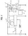
- a preliminary step, a starting step and a restoring step are carried out in order using the starter system as shown in Fig. 1 to start an engine from an idling stop condition.
- the starter system used in this embodiment includes a starter 1 provided with a magnet switch 2, a relay 3 for opening and closing a main contact 21 of the magnet switch 2 and a battery B, and a controller 4 that controls the starter 1 and the relay 3.
- the starter 1 has a pinion 12 that is journaled to be movable axially.
- the magnet switch 2 serving as a push-out means that pushes out the pinion 12 toward ring gear R of engine E.
- a motor 11 drives the pinion 12 rotatively.
- the magnet switch 2 is provided with a solenoid coil 22 which comprises a pull-in coil and a holding coil, a plunger 23 is attracted by the solenoid coil 22, and the main contact 21 is opened and closed by the plunger 23.
- One end of a driving lever 13 with a driving spring (not shown) attached thereto is connected mechanically to one end of the plunger 23.
- the magnet switch 2 causes the pinion 12 to be pushed out toward or retracted from the ring gear R through the driving lever 13. Where the magnet switch 2 attracts the plunger 23 and the pinion 12 abuts an end face of the ring gear R, the pinion 12 is urged toward the ring gear R with the biasing force of the driving spring.
- the relay 3 is a normally OFF type relay which opens and closes between a positive terminal of the battery B and a battery terminal of the main switch 21. Only while a relay coil 32 is energized by the controller 4, the relay 3 closes a relay contact 31.
- the controller 4 which incorporates a microcomputer, controls the magnet switch 2 of the starter 1 and the relay 3 according to various signals, including an engine revolution signal and a brake pedal position signal.
- the engine is started from an idling stop condition by carrying out the preliminary step, the starting step and the restoring step in order.
- the pinion 12 of the starter 1 is pushed out at least halfway by the magnet switch 2 (a push-out means) so that the pinion abuts against or meshes with the ring gear R of the engine E.
- the pinion 12 is driven rotatably by the motor 11 of the starter 1 and the rotating pinion is meshed with the ring gear R, then the engine is cranked and started.
- the magnet switch 2 is restored, thereby allowing the pinion 12 to return to its original position spaced away from the ring gear R. In this step the motor 11 is de-energized.
- steps S1 and S2 ensure that the vehicle has stopped with the ignition switch of key switch K turned ON.
- steps S3 and S4 ensure that upon receipt, of a command signal for stopping the engine E automatically, the engine was stopped automatically and came into an idling stop condition.
- the preliminary step is carried out in processing steps S5 and S6, in which the magnet switch 2 operates and the pinion 12 is pushed against the ring gear R through the driving lever 13 with a driving spring attached thereto.
- a stand-by state after termination of the preliminary step is maintained while waiting for a command signal generated, for example, upon release of the vehicle driver's foot from the brake pedal and which causes the engine E to start automatically.
- step S7 If an engine E starting signal is automatically detected in step S7, the starting step is carried out in processing steps S8 to S10.
- the magnet switch 2 operated in the above preliminary step and the main contact 21 is already closed. So, if the relay coil 32 is energized and the relay contact 31 closes in the processing step S8, the motor 11 is energized in the processing step S9.
- the pinion 12 which is urged by the driving spring attached to the driving lever 13 turns into a deep mesh with the ring gear R. Further, the motor 11 drives and rotates the pinion 12, with consequent engine start-up.
- 11 is energized for a predetermined time sufficient for engine startup, or the ignition pulse from the engine or an output of a revolution sensor is detected.
- step S10 If the engine starts in step S10, the restoring step is carried out last. More specifically, in a processing step S11, the solenoid coil 22 of the magnet switch 2 is de-energized. Then, when the plunger 23 is restored to its original position by a return spring (not shown), the pinion 12 also returns from the ring gear R to its original position through the driving lever 13. In a processing step S12, the relay coil 32 is de-energized and the relay contact 31 returns to its original open position. Now, a series of engine starting operations in an idling stop condition are completed.
- the preliminary step (processing steps S5 and S6) is carried out and the starter pinion 12 is pushed out at least until abutment against the ring gear R of the engine E by the magnet switch 2 of the starter 1.
- the pinion 12 abuts against or meshes with the ring gear R. Since in many cases the pinion teeth 12 and the teeth of the ring gear R are not in positional coincidence with each other, the pinion abuts against an end face of the ring gear R and is urged against the ring gear by the magnet switch 2 and the driving spring.
- the pinion teeth and the ring gear teeth are positionally coincident, the pinion 12 is pushed out sufficiently deeply into mesh with the ring gear R.
- the starting step (processing steps S8-S10) is carried out, in which the pinion 12 is rotated by the motor 11 of the starter 1.
- the pinion 12 was abutted against the ring gear R in the preliminary step described above, the pinion 12 meshes with the ring gear during one-pitch rotation of the pinion and is further pushed into a sufficiently deep mesh with the ring gear.
- the pinion 12 meshes with the ring gear R, since the pinion has already been pushed against the ring gear and engages the ring gear as soon as it starts rotating, engaging shock is suppressed to an extremely small degree.
- the pinion 12 rotates the ring gear immediately.
- the engine E is cranked by the motor 11 via the pinion and the ring gear and is thus started.
- the restoring step (processing steps S11 and S12) is carried out, whereby the pinion 12 of the starter 1 is restored to its original position spaced away from the ring gear R of the engine. Therefore, the pinion 12 is spaced away from the ring gear R during normal engine operation E and the pinion does not generate engaging noise or wear.
- the pinion 12 abuts an end face of the ring gear R or already meshed with the ring gear. Therefore, even if the pinion 12 starts rotating in the starting step, engaging shock thereof is extremely small. Or, if the pinion is already engaged with the ring gear, no engaging shock occurs. As a result, not only is noise and vibration caused by engaging shock of the pinion 12 reduced during start-up, but also the durability of the starter 1 including the pinion is improved.
- the pinion 12 abuts or already is engaged with the ring gear R, as noted earlier. In the starting step, therefore, the pinion 12 shifts to its engaged state with the ring gear R immediately from its abutted state against the ring gear. Or, where the pinion 12 is already meshed with the ring gear R in the preliminary step, the engine E is cranked upon rotation of the pinion. As a result, engine E can be started rapidly with little delay.
- the pinion 12 returns to its original position and leaves the ring gear R, so that during normal engine operation E, the pinion is spaced away from the ring gear.
- the pinion 12 does not rotate during normal engine operation E and therefore the durability of the starter 1 including the pinion is improved.
- the quietness during vehicular running is improved as the pinion 12 does not generate an engaging noise during vehicular running.
- a meshing step can be used that involves energizing the motor 11 of the starter 1 for only a very short time, causing the pinion 12 to turn slightly and thereby keeping the pinion engaged with the ring gear R.
- the pinion can be kept engaged with the ring gear by energizing the motor 11 of the starter 1 for only a very short time in the meshing step.
- the motor 11 is energized for only a very short time to turn the pinion 12 only a little, since the pinion already abuts the ring gear and is urged by the driving spring, the pinion turns to an angular position in which it meshes with the ring gear R, and both are meshed.
- the pinion 12 need not turn fully once, but can turn to an angular position corresponding to one pitch of the pinion teeth.
- the short-time energization for the motor 11 may be repeated multiple times, and a single turning angle of the pinion 12 may be less than one pitch.
- the energization time for the motor 11 is very short, so that the turning angular velocity of the pinion 12 is very low in comparison with that in the starting step. As such, the pinion turns slowly into mesh with the ring gear R. For this reason, there is little engaging shock of the pinion 12 and the durability of the starter 1 is further improved. Also, the engaging shock is not sensed by the vehicle occupants.
- the pinion 12 is already in a sufficiently deep mesh with the ring gear R when the starting step is carried out after termination of the idling stop condition. In the starting step, therefore, no engaging shock occurs, whereby the noise and shock during engine start-up are suppressed and the durability of the starter 1 is improved.
- the engine E is cranked as soon as the starting step begins and thus engine start-up is effected more rapidly. According to this modification, therefore, in addition to the foregoing effects attained by the first embodiment, the quietness during engine start-up and the durability of the starter 1 are further improved and the starting of the engine becomes more rapid.
- a relay 3 is normally ON and a relay contact 31 is closed when a relay coil 32 is not energized.
- the starter system used in this embodiment is different from the starter system used in the first embodiment.
- the configuration of a key switch K used is also somewhat different from that used in the starter system in the first embodiment.
- the key switch K used in the second embodiment has a solenoid coil 22 as a magnetic switch that can be energized directly from the battery B. Accordingly, the control logic in the controller 4 is also properly modified from that used in the first embodiment.
- the starter system used in this embodiment is basically the same as that used in the first embodiment.
- engine E can be started. More specifically, since the relay contact 31 is closed, the engine E can be started by operating the key switch K manually and thereby causing the magnet switch 2 to operate directly from the battery B.
- the engine starting method in an idling stop condition according to the second embodiment of the present invention includes a preliminary step, a starting step and a restoring step, with a meshing step being included in an initial stage of the preliminary step.
- the engine starting method of this embodiment will be described below according to the procedure illustrated in a flow chart of Fig. 4.
- the engine starting method in an idling stop condition is the same as in the first embodiment until it is determined in steps S1 to S4 that the vehicle has entered into an idling stop condition.
- the preliminary step is carried out, and in a processing step S5 the magnet switch 2 operates and the pinion 12 is pushed out at least halfway so as to abut or engage with the ring gear R.
- the relay contact 31 of the relay 3 is closed, so upon closing of the main contact 21 of the magnet switch 2, the motor 11 of the starter 1 is energized for only a very short time in step S51.
- the relay coil 32 is energized after the lapse of a predetermined time, and until opening of the relay 31 the motor 11 is energized and the pinion 12 is turned only slightly.
- the pinion 12 meshes with the ring gear R and is pushed more deeply into mesh with the ring gear R firmly by means of the magnet switch 2 and the driving lever 13.
- a meshing step wherein the motor 1 is energized for only a very short time to rotate the pinion only slightly, thereby keeping the pinion engaged with the ring gear.
- a determining step S7 which waits for a command signal to issue for starting the engine E automatically from an idling stop condition.
- this automatic start command signal is detected, the supply of electric power to the relay coil 32 of the normally closed relay 3 is stopped in a processing step S71, the relay contact 31 closes and the motor 11 of the starter 1 is energized.
- the engine E starts at processing step S10.
- a processing step S11 which follows, the supply of electric power to the solenoid coil 22 of the magnetic switch 2 is stopped and the magnet switch and the pinion 12 return to their original positions.
- step S71 to S10 the starting step wherein the pinion 12 is rotated by the motor 11 and the engine E is cranked and started through the pinion 12 meshing with the ring gear R is carried out. Subsequently, in step S11, the pinion 12 is restored to its original position of being spaced apart from the ring gear R as in the first embodiment.
- the engaging shock between the pinion 12 and the ring gear R is diminished and the engine E can be started rapidly from an idling stop condition while satisfying both durability of the starter 1 and quietness. Also, since the pinion 12 is already meshed with the ring gear R in the preliminary step, the quietness during engine start-up and the durability of the starter 1 are further improved. In addition, the engine is started more rapidly.
- a starter system used in an engine starting method in an idling stop condition according to the third embodiment of the present invention replaces the magnet switch 2 used in the first embodiment with an attracting solenoid 2' not having the main switch 21.
- Other constructional points of the starter system of this third embodiment are the same as in the starter system of the first embodiment.
- the control logic of the controller 4 for the solenoid 22 and the relay 3 is the same as in the first embodiment. Since a starter 1 uses the attracting solenoid 2' not having the main contact 21 in place of the magnet switch 2, the starter 1 is manufactured inexpensively.
- the working procedure of the present embodiment is carried out according to the flow chart of Fig. 2, provided the magnet switch 2 is replaced by the attracting solenoid 2' in processing steps S5 and S11. It is possible to practice an engine starting method in an idling stop condition including a meshing step corresponding to the first modification of the first embodiment.
- FIG. 6 is an energizing circuit diagram in a starter system for a vehicle embodying the present invention.
- a starter 100 for starting an engine is provided with a starter motor 200 for cranking an engine and a magnet switch 300 for turning ON and OFF the starter motor 2.
- the starter motor 200 is a well-known starter which when energized produces a torque for driving the engine.
- the starter motor 200 is composed of a field coil 2a and an armature 2b with an armature coil mounted thereon.
- a coil 3a of the magnet switch 300 is connected to a vehicular battery through a starter relay 4. Upon turning ON of the starter relay 4, the coil 3a of the magnet switch 300 is energized and produces a magnetic force to turn ON the magnet switch 300, which is a normally open movable contact.
- the coil 4a of the starter relay 400 is directly connected to the battery 5 through a key switch 6, and when the key switch 6 is connected to a starter terminal 6a, the coil 4a of the starter relay 400 is energized and produces a magnetic force to turn ON the starter relay 400 which is a normally open movable contact.
- a starting control means ( “starting ECU” hereinafter) 7 energizes the coil 4a of the starter relay 4, whereupon the starter relay 400 turns ON.
- the starting ECU 7, which controls the starter relay 4 operates to start the engine when the vehicle starts moving from a stop condition, such as from a traffic signal.
- the magnet switch 300 is turned ON to energize the starter motor 2.
- the ECU for the engine is provided with an eco-run system control section for an eco-run system which, when the accelerator pedal is released and the brake is depressed, stops the engine automatically and causes the engine to start before the vehicle starts moving after release of the brake.
- the Engine ECU outputs the foregoing automatic start signal to the starting ECU 7.
- step S100 determines if the key switch 6 is connected to the ON terminal 6b. If it is not, the flow returns to step S100. If so, a whether the automatic start signal has been received from the Engine ECU (step S2) is determined. If the result in step S200 is negative, the flow returns to step S100.
- step S200 determines the Engine ECU has emitted the automatic start signal
- the coil 4a of the starter relay 400 is energized (step S300).
- the starter relay 400 turns ON, the coil 3a of the magnet switch 300 is energized to turn ON the magnet switch, and the battery 5 is connected to the starter motor 2, so that the starter motor 200 cranks the engine.
- step S4 whether the automatic start signal transmitted from the Engine ECU has terminated (step S4) is determined. In other words, whether the engine has started with start-up of the starter motor 2, the engine speed N is larger than a predetermined level N0 (N>N0) and the Engine ECU has stopped emitting the automatic start signal is determined. If the result is negative, the flow returns to step S400 because the starting of the engine has not been completed yet. If step S400 is affirmative (engine started), starter 100 is stopped. That is, the coil 4a of the starter relay 400 is turned OFF to turn OFF the magnet switch 300 (step S500). As a result, the starter motor 200 is de-energized and the starter 100 stops.
- the starter 100 is provided with a pinion 110 capable of being engaged with and disengaged from a ring gear 10 of the engine.
- the pinion 110 is driven rotatively by the starter motor 2.
- the pinion 110 is set at a position where it is engaged with the ring gear 10 by a biasing force of a metallic spring (corresponding to the biasing means, not shown).
- the starter 100 is provided with a pinion actuator 130 for disengaging the pinion 110 from the ring gear 10 against the biasing force of the spring.
- the pinion actuator 130 used in this embodiment is made up of a pinion actuating coil 13a and a pinion actuating solenoid 13b which causes the pinion 110 to be disengaged from the ring gear 10 with a magnetic force generated by the pinion actuating coil.
- the pinion actuating solenoid 13b is operated by a control means for disengagement which is programmed in the starting ECU 7.
- the control means for disengagement causes the pinion actuator 130 to operate during engine start-up, thereby disengaging the pinion 110 from the ring gear 10.
- the starting ECU 7 is provided to input the engine speed from the Engine ECU and cause the pinion actuator 130 to operate for disengaging the pinion 110 from the ring gear 10 upon increase of the engine speed N to a greater extent than the predetermined level N0 (N>N0).
- the starter 100 is provided with a mechanical engaging means 14 which, upon disengagement of the pinion 110 from the ring gear 10, mechanically engages a member (the pinion actuating solenoid 13b in this embodiment) which moves integrally with the pinion 110, to keep the pinion disengaged from the ring gear 10.
- the mechanical engaging means is an engaging cutout portion 14a formed in the pinion actuating solenoid 13b and an engaging piece 14b for engagement with the cutout portion 14a.
- the engaging piece 14b engages the cutout portion 14a automatically to keep the pinion 110 disengaged from the ring gear 10.
- the pinion actuating solenoid 13b slides integrally with the pinion 110 and is rotatable with respect to the pinion 110 and does not rotate when the pinion 110 rotates.
- the starter 100 is provided with a releasing actuator for releasing the mechanically engaged state of the mechanical engaging means 14.
- the releasing actuator 15 used in this embodiment includes a releasing coil 15a and a releasing solenoid 15b provided with the engaging piece 14b which is disengaged by a magnetic force generated from the releasing coil 15a.
- the releasing solenoid 15b is operated by a control means for engagement which is programmed in the starting ECU 7.
- the control means for engagement causes the releasing actuator 15 to operate and release the mechanically engaged state of the mechanical engaging means 14, thereby allowing the pinion 110 to mesh with the ring gear 10.
- N input from the Engine ECU
- the starting ECU 7 first determines whether the engine is operating (step S11). That is, the starting ECU 7 determines whether the engine has been started manually or by the eco-run system. More specifically, the starting ECU determines whether the engine speed N, after engine start-up, is higher than the predetermined engine speed N0 (N>N0). If the result in step S110 is negative, the ECU 7 determines that the engine has not been started, and the flow returns to step S110 to keep the pinion 110 and the ring gear 10 engaged with each other.
- step S110 If the result in step S110 is affirmative, i.e., if the engine has started, the pinion actuator 130 disengages the pinion 110 from the ring gear 10 (step S120). More specifically, the pinion actuating coil 13a is turned ON until complete disengagement of the pinion 110 from the ring gear 10, causing the pinion to be disengaged from the ring gear 10.
- the timing at which the pinion actuating coil 13a is to be turned OFF may be set using a timer or by disposing a sensor in such a manner that the pinion actuating coil 13a is turned OFF upon disengagement of the pinion 110 from the ring gear 10.
- the cutout portion 14a of the pinion actuating solenoid 13b engages the engaging piece 14b, whereby the pinion 110 is kept disengaged from the ring gear 10.
- the pinion 110 is meshed with the ring gear 10 with the biasing force of the spring.
- the rest position is where the pinion 110 engages the ring gear 10
- electric power is not consumed. Therefore, even if the vehicle stop time becomes long due to idling stop or even if the frequency of vehicle stop due to traffic congestion increases, the consumption of the battery 5 is suppressed.
- the pinion 110 While the engine stops, as mentioned above, the pinion 110 is meshed with the ring gear 10, so that no engaging time is needed when the engine starts and it is possible to shorten the time required for starting the engine in the eco-system.
- the pinion actuator 130 operates and the pinion 110 is disengaged from the ring gear 10.
- the engaging piece 14b engages the cutout portion 14a formed in the pinion actuating solenoid 13b, whereby the pinion 110 is kept disengaged from the ring gear 10. Consequently, it becomes unnecessary to supply energy for disengaging the pinion 110 from the ring gear 10 while the engine is operating and hence it is possible to suppress the consumption of an electric current during operation of the engine.
- the releasing actuator 15 operates to disengage the cutout portion 14a and the engaging piece 14b from each other, so that the pinion 110 is pushed back to its rest position by the action of the spring as the biasing means. Consequently, with small power consumption, it is possible to bring back the pinion 110 to the position of engagement with the ring gear 10 which position is the rest position.
- the starter 100 described in this embodiment not only permits shortening of the engine starting time but also permits suppressing the amount of electric power which the engine starter system including the starter 100 consumes for the eco-run system.
- the circuit configuration, the configuration of the starter 100 and how to control described in the above embodiment are merely an example for explaining the embodiment and may be changed as necessary.
Landscapes
- Engineering & Computer Science (AREA)
- Chemical & Material Sciences (AREA)
- Combustion & Propulsion (AREA)
- Mechanical Engineering (AREA)
- General Engineering & Computer Science (AREA)
- Control Of Vehicle Engines Or Engines For Specific Uses (AREA)
Abstract
Description
Claims (5)
- An engine starting method for starting an engine from an idling stop condition, comprising:providing a starter (100) comprising a pinion (110) journaled axially movably, a push-out means (2) for pushing out the pinion (110) toward a ring gear (10) of the engine, and a motor (2) for driving the pinion (110) rotatably;pushing the pinion (110) out at least halfway with the push-out means (2) in a preliminary step to abut the pinion (110) against or mesh with the ring gear (10);rotating the pinion (110) by the motor (2) and bringing the rotating pinion (110) into mesh with the ring gear (10), and thereafter cranking the engine to start the engine in a starting step, said starting step being after said preliminary step; andrestoring the pinion (110) to an original position spaced away from the ring gear (10) in a restoring step, said restoring step being after said starting step.
- The method as claimed in claim 1, further comprising a meshing step of energizing the motor (2) for only a very short time to cause the pinion (110) to turn slightly to keep the pinion (110) engaged with the ring gear (10), said meshing step being performed with the preliminary step.
- A starter (100) system for a vehicle, comprising:a pinion (110) engagable with a ring gear (10) of an engine;a starter (100) motor (2) that rotatably drives the pinion (110);a biasing means for engaging the pinion (110) with the ring gear (10);a pinion (110) actuator for disengaging the pinion (110) from the ring gear (10) against a biasing force of the biasing means; anda control means for disengagement which causes the pinion (110) actuator to operate during engine start-up, thereby causing the pinion (110) to be disengaged from the ring gear (10).
- A starter (100) system for a vehicle according to claim 3, further comprising a mechanical engaging means which mechanically engages with a member adapted to move integrally with the pinion (110) to keep the pinion (110) disengaged from the ring gear (10) when the pinion (110) is disengaged from the ring gear (10) by the pinion (110) actuator.
- A starter (100) system for a vehicle according to claim 4, further comprising:a releasing actuator for releasing the engaged state of the mechanical engaging means; anda control means for engagement which causes the releasing actuator to mesh the pinion (110) with the ring gear (10) when the engine stops.
Applications Claiming Priority (4)
| Application Number | Priority Date | Filing Date | Title |
|---|---|---|---|
| JP2000135570 | 2000-05-09 | ||
| JP2000135570A JP4232069B2 (en) | 2000-05-09 | 2000-05-09 | How to start the engine at idle stop |
| JP2000280407A JP2002089422A (en) | 2000-09-14 | 2000-09-14 | Starting device for vehicles |
| JP2000280407 | 2000-09-14 |
Publications (3)
| Publication Number | Publication Date |
|---|---|
| EP1154153A2 true EP1154153A2 (en) | 2001-11-14 |
| EP1154153A3 EP1154153A3 (en) | 2003-07-30 |
| EP1154153B1 EP1154153B1 (en) | 2007-04-04 |
Family
ID=26591528
Family Applications (1)
| Application Number | Title | Priority Date | Filing Date |
|---|---|---|---|
| EP01110593A Expired - Lifetime EP1154153B1 (en) | 2000-05-09 | 2001-04-30 | Engine starting method in idling stop condition |
Country Status (3)
| Country | Link |
|---|---|
| US (1) | US6651603B2 (en) |
| EP (1) | EP1154153B1 (en) |
| DE (1) | DE60127611T2 (en) |
Cited By (1)
| Publication number | Priority date | Publication date | Assignee | Title |
|---|---|---|---|---|
| EP1939444A3 (en) * | 2006-12-28 | 2012-01-04 | Hitachi, Ltd. | Starter |
Families Citing this family (35)
| Publication number | Priority date | Publication date | Assignee | Title |
|---|---|---|---|---|
| US6895175B2 (en) * | 2001-10-01 | 2005-05-17 | Cummins, Inc. | Electrical control circuit and method |
| JP3866192B2 (en) * | 2002-12-10 | 2007-01-10 | 三菱電機株式会社 | Engine starter |
| DE102005004326A1 (en) * | 2004-08-17 | 2006-02-23 | Robert Bosch Gmbh | Starting device for an internal combustion engine with separate engagement and starting process |
| JP2006100760A (en) * | 2004-09-02 | 2006-04-13 | Casio Comput Co Ltd | Thin film transistor and manufacturing method thereof |
| US7218010B2 (en) * | 2005-02-15 | 2007-05-15 | General Motors Corporation | Engine restart apparatus and method |
| DE102005048599A1 (en) * | 2005-10-06 | 2007-04-12 | Robert Bosch Gmbh | Starting device for cranking internal combustion engines |
| DE102005048598B4 (en) * | 2005-10-06 | 2016-06-30 | Robert Bosch Gmbh | Starting device for cranking internal combustion engines |
| DE102005049092B4 (en) * | 2005-10-13 | 2016-06-02 | Robert Bosch Gmbh | A method for meshing the starter pinion of a starter in the starter tooth circuit of an internal combustion engine when the internal combustion engine |
| DE102006047608A1 (en) * | 2006-10-09 | 2008-04-10 | Robert Bosch Gmbh | Starter for internal combustion engines with relief switch |
| JP4186085B2 (en) * | 2007-03-02 | 2008-11-26 | 三菱自動車工業株式会社 | Engine start control device |
| US8561588B2 (en) * | 2008-03-07 | 2013-10-22 | GM Global Technology Operations LLC | Engine stop/start system and method of operating same |
| JP5007839B2 (en) * | 2008-09-02 | 2012-08-22 | 株式会社デンソー | Engine automatic stop / start control device |
| JP4737571B2 (en) * | 2008-09-08 | 2011-08-03 | 株式会社デンソー | Engine starter |
| JP4702427B2 (en) * | 2008-10-10 | 2011-06-15 | 株式会社デンソー | Engine start control device |
| US8370051B2 (en) | 2009-01-05 | 2013-02-05 | Ford Global Technologies, Llc | Methods and systems for assisted direct start control |
| EP2211051B8 (en) * | 2009-01-21 | 2019-09-11 | Denso Corporation | System for restarting internal combustion engine |
| JP5369843B2 (en) * | 2009-04-02 | 2013-12-18 | 株式会社デンソー | Engine starter |
| DE102009028294A1 (en) * | 2009-08-06 | 2011-02-10 | Robert Bosch Gmbh | Device for starting an internal combustion engine |
| DE102009028870A1 (en) * | 2009-08-26 | 2011-03-03 | Robert Bosch Gmbh | Method for engaging a starting pinion of a starter device in a ring gear of an internal combustion engine |
| DE102009029288A1 (en) * | 2009-09-09 | 2011-03-10 | Robert Bosch Gmbh | Device for starting an internal combustion engine with a reduced number of control lines |
| DE102009055371A1 (en) * | 2009-12-29 | 2011-06-30 | Robert Bosch GmbH, 70469 | Starter with engagement recognition function |
| US8141534B2 (en) | 2010-02-03 | 2012-03-27 | Ford Global Technologies, Llc | Methods and systems for assisted direct start control |
| JP2011163321A (en) * | 2010-02-15 | 2011-08-25 | Denso Corp | Engine start control device |
| US8328687B2 (en) | 2010-07-09 | 2012-12-11 | Ford Global Technologies, Llc | Method for controlling an engine that may be automatically stopped |
| US8864623B2 (en) | 2010-07-09 | 2014-10-21 | Ford Global Technologies, Llc | Method for controlling a transmission coupled to an engine that may be automatically stopped |
| US8414456B2 (en) | 2010-07-09 | 2013-04-09 | Ford Global Technologies, Llc | Method for starting an engine |
| WO2012008046A1 (en) * | 2010-07-16 | 2012-01-19 | トヨタ自動車株式会社 | Engine starting device and vehicle mounted with same |
| JP5628714B2 (en) * | 2011-03-11 | 2014-11-19 | 日立オートモティブシステムズ株式会社 | Engine starter for vehicle |
| WO2012139123A2 (en) | 2011-04-07 | 2012-10-11 | Remy Technologies, Llc | Starter machine system and method |
| US9184646B2 (en) | 2011-04-07 | 2015-11-10 | Remy Technologies, Llc | Starter machine system and method |
| JP5564476B2 (en) * | 2011-08-30 | 2014-07-30 | 日立オートモティブシステムズ株式会社 | Automotive control device |
| US8860235B2 (en) | 2012-02-24 | 2014-10-14 | Remy Technologies, Llc | Starter machine system and method |
| US8872369B2 (en) | 2012-02-24 | 2014-10-28 | Remy Technologies, Llc | Starter machine system and method |
| US8829845B2 (en) | 2012-02-28 | 2014-09-09 | Remy Technologies, Llc | Starter machine system and method |
| US8733190B2 (en) | 2012-04-25 | 2014-05-27 | Remy Technologies, Llc | Starter machine system and method |
Family Cites Families (16)
| Publication number | Priority date | Publication date | Assignee | Title |
|---|---|---|---|---|
| GB426882A (en) * | 1932-10-24 | 1935-04-11 | Eclipse Machine Co | Improvements in engine starter controls |
| DE1022053B (en) * | 1955-03-10 | 1958-01-02 | Asea Ab | Turning device for internal combustion engines from emergency power sets |
| US4305002A (en) * | 1978-11-20 | 1981-12-08 | Facet Enterprises, Inc. | Two stage starter drive system |
| US4418289A (en) * | 1978-11-20 | 1983-11-29 | Facet Enterprises, Incorporated | Two stage starter drive system |
| US4551630A (en) * | 1984-05-31 | 1985-11-05 | General Motors Corporation | Electric starting system |
| JPH0735770B2 (en) * | 1984-06-06 | 1995-04-19 | 日本電装株式会社 | Starter |
| FR2598753B1 (en) | 1986-05-16 | 1988-08-26 | Valeo | STARTING DEVICE FOR INTERNAL COMBUSTION ENGINE |
| JPH0381564A (en) | 1989-08-23 | 1991-04-05 | Nippondenso Co Ltd | Apparatus for engaging starter |
| IT1263109B (en) * | 1992-03-24 | 1996-07-30 | Magneti Marelli Spa | STARTING SYSTEM FOR AN INTERNAL COMBUSTION ENGINE |
| DE4301067C1 (en) * | 1993-01-16 | 1994-01-27 | Daimler Benz Ag | Starter with a protective device against damage due to a quick repeat start |
| JPH08261117A (en) | 1995-03-28 | 1996-10-08 | Nippondenso Co Ltd | Starter dynamo |
| JPH1130139A (en) | 1997-07-09 | 1999-02-02 | Hitachi Ltd | Engine automatic stop / start device |
| JP3081564B2 (en) | 1997-08-01 | 2000-08-28 | エムケー精工株式会社 | Vehicle type discriminating device in car washing device and car washing device provided with vehicle shape discriminating device |
| JPH11218068A (en) | 1998-02-03 | 1999-08-10 | Hitachi Ltd | Engine starter |
| JP4108140B2 (en) * | 1998-03-13 | 2008-06-25 | ローベルト ボツシユ ゲゼルシヤフト ミツト ベシユレンクテル ハフツング | Starter for internal combustion engine |
| JP2000045920A (en) * | 1998-07-30 | 2000-02-15 | Hitachi Ltd | Engine starting device, starting method, and starter motor |
-
2001
- 2001-04-30 DE DE60127611T patent/DE60127611T2/en not_active Expired - Lifetime
- 2001-04-30 EP EP01110593A patent/EP1154153B1/en not_active Expired - Lifetime
- 2001-05-07 US US09/849,274 patent/US6651603B2/en not_active Expired - Lifetime
Cited By (2)
| Publication number | Priority date | Publication date | Assignee | Title |
|---|---|---|---|---|
| EP1939444A3 (en) * | 2006-12-28 | 2012-01-04 | Hitachi, Ltd. | Starter |
| EP2647833A3 (en) * | 2006-12-28 | 2014-03-05 | Hitachi Ltd. | Starter |
Also Published As
| Publication number | Publication date |
|---|---|
| EP1154153A3 (en) | 2003-07-30 |
| US6651603B2 (en) | 2003-11-25 |
| US20010047785A1 (en) | 2001-12-06 |
| EP1154153B1 (en) | 2007-04-04 |
| DE60127611D1 (en) | 2007-05-16 |
| DE60127611T2 (en) | 2007-12-27 |
Similar Documents
| Publication | Publication Date | Title |
|---|---|---|
| EP1154153B1 (en) | Engine starting method in idling stop condition | |
| JP4214401B2 (en) | Engine automatic stop / restart device | |
| CN102112728B (en) | Method and device for start-stop-control of an internal combustion engine | |
| US6634332B2 (en) | Engine start-stop control system | |
| CN102828878B (en) | In-vehicle engine start control apparatus | |
| JP5471572B2 (en) | Engine starter | |
| JP2011163321A (en) | Engine start control device | |
| JPH076469B2 (en) | Automatic engine starting method and device | |
| US7082914B2 (en) | Method for controlling idle stop-and-go system | |
| JP2003003938A (en) | Engine automatic stop / start device and start method | |
| JP2000266172A (en) | Vehicle control device | |
| JP5224005B2 (en) | Starter control device, starter control method, and engine starter | |
| JP4232069B2 (en) | How to start the engine at idle stop | |
| JP3551783B2 (en) | Vehicle starter device | |
| JP2002221133A (en) | Starting device for vehicles | |
| CN103348125B (en) | Run method and the starting system of starting system | |
| CN103189636B (en) | The guard method of high moment of inertia starter | |
| JPH11218068A (en) | Engine starter | |
| JP6113329B1 (en) | Starter and starter control method | |
| WO2013136840A1 (en) | Engine starter electric motor device | |
| JPS58164438A (en) | Engine starting device of vehicle equipped with automatic transmission | |
| JP2002303232A (en) | Engine starter | |
| JP5001993B2 (en) | Engine starter | |
| JP2002089422A (en) | Starting device for vehicles | |
| JP2000045920A (en) | Engine starting device, starting method, and starter motor |
Legal Events
| Date | Code | Title | Description |
|---|---|---|---|
| PUAI | Public reference made under article 153(3) epc to a published international application that has entered the european phase |
Free format text: ORIGINAL CODE: 0009012 |
|
| AK | Designated contracting states |
Kind code of ref document: A2 Designated state(s): AT BE CH CY DE DK ES FI FR GB GR IE IT LI LU MC NL PT SE TR |
|
| AX | Request for extension of the european patent |
Free format text: AL;LT;LV;MK;RO;SI |
|
| PUAL | Search report despatched |
Free format text: ORIGINAL CODE: 0009013 |
|
| AK | Designated contracting states |
Designated state(s): AT BE CH CY DE DK ES FI FR GB GR IE IT LI LU MC NL PT SE TR |
|
| AX | Request for extension of the european patent |
Extension state: AL LT LV MK RO SI |
|
| 17P | Request for examination filed |
Effective date: 20031016 |
|
| AKX | Designation fees paid |
Designated state(s): DE FR IT |
|
| 17Q | First examination report despatched |
Effective date: 20050302 |
|
| GRAP | Despatch of communication of intention to grant a patent |
Free format text: ORIGINAL CODE: EPIDOSNIGR1 |
|
| GRAS | Grant fee paid |
Free format text: ORIGINAL CODE: EPIDOSNIGR3 |
|
| GRAA | (expected) grant |
Free format text: ORIGINAL CODE: 0009210 |
|
| AK | Designated contracting states |
Kind code of ref document: B1 Designated state(s): DE FR IT |
|
| REF | Corresponds to: |
Ref document number: 60127611 Country of ref document: DE Date of ref document: 20070516 Kind code of ref document: P |
|
| ET | Fr: translation filed | ||
| PLBE | No opposition filed within time limit |
Free format text: ORIGINAL CODE: 0009261 |
|
| STAA | Information on the status of an ep patent application or granted ep patent |
Free format text: STATUS: NO OPPOSITION FILED WITHIN TIME LIMIT |
|
| 26N | No opposition filed |
Effective date: 20080107 |
|
| PGFP | Annual fee paid to national office [announced via postgrant information from national office to epo] |
Ref country code: IT Payment date: 20140423 Year of fee payment: 14 Ref country code: FR Payment date: 20140422 Year of fee payment: 14 |
|
| PG25 | Lapsed in a contracting state [announced via postgrant information from national office to epo] |
Ref country code: IT Free format text: LAPSE BECAUSE OF NON-PAYMENT OF DUE FEES Effective date: 20150430 |
|
| REG | Reference to a national code |
Ref country code: FR Ref legal event code: ST Effective date: 20151231 |
|
| PG25 | Lapsed in a contracting state [announced via postgrant information from national office to epo] |
Ref country code: FR Free format text: LAPSE BECAUSE OF NON-PAYMENT OF DUE FEES Effective date: 20150430 |
|
| PGFP | Annual fee paid to national office [announced via postgrant information from national office to epo] |
Ref country code: DE Payment date: 20190418 Year of fee payment: 19 |
|
| REG | Reference to a national code |
Ref country code: DE Ref legal event code: R119 Ref document number: 60127611 Country of ref document: DE |
|
| PG25 | Lapsed in a contracting state [announced via postgrant information from national office to epo] |
Ref country code: DE Free format text: LAPSE BECAUSE OF NON-PAYMENT OF DUE FEES Effective date: 20201103 |