EP1154128A2 - Variable valve timing system - Google Patents
Variable valve timing system Download PDFInfo
- Publication number
- EP1154128A2 EP1154128A2 EP01111345A EP01111345A EP1154128A2 EP 1154128 A2 EP1154128 A2 EP 1154128A2 EP 01111345 A EP01111345 A EP 01111345A EP 01111345 A EP01111345 A EP 01111345A EP 1154128 A2 EP1154128 A2 EP 1154128A2
- Authority
- EP
- European Patent Office
- Prior art keywords
- hydraulic pressure
- valve timing
- angle chamber
- control condition
- advanced angle
- Prior art date
- Legal status (The legal status is an assumption and is not a legal conclusion. Google has not performed a legal analysis and makes no representation as to the accuracy of the status listed.)
- Granted
Links
- 230000007246 mechanism Effects 0.000 claims abstract description 43
- 230000010363 phase shift Effects 0.000 claims abstract description 6
- 239000012530 fluid Substances 0.000 claims description 44
- 238000002485 combustion reaction Methods 0.000 claims description 14
- 230000000979 retarding effect Effects 0.000 claims description 3
- 230000002093 peripheral effect Effects 0.000 description 7
- VIKNJXKGJWUCNN-XGXHKTLJSA-N norethisterone Chemical compound O=C1CC[C@@H]2[C@H]3CC[C@](C)([C@](CC4)(O)C#C)[C@@H]4[C@@H]3CCC2=C1 VIKNJXKGJWUCNN-XGXHKTLJSA-N 0.000 description 5
- 239000000498 cooling water Substances 0.000 description 1
- 238000010586 diagram Methods 0.000 description 1
Images




Classifications
-
- F—MECHANICAL ENGINEERING; LIGHTING; HEATING; WEAPONS; BLASTING
- F01—MACHINES OR ENGINES IN GENERAL; ENGINE PLANTS IN GENERAL; STEAM ENGINES
- F01L—CYCLICALLY OPERATING VALVES FOR MACHINES OR ENGINES
- F01L1/00—Valve-gear or valve arrangements, e.g. lift-valve gear
- F01L1/34—Valve-gear or valve arrangements, e.g. lift-valve gear characterised by the provision of means for changing the timing of the valves without changing the duration of opening and without affecting the magnitude of the valve lift
- F01L1/344—Valve-gear or valve arrangements, e.g. lift-valve gear characterised by the provision of means for changing the timing of the valves without changing the duration of opening and without affecting the magnitude of the valve lift changing the angular relationship between crankshaft and camshaft, e.g. using helicoidal gear
- F01L1/3442—Valve-gear or valve arrangements, e.g. lift-valve gear characterised by the provision of means for changing the timing of the valves without changing the duration of opening and without affecting the magnitude of the valve lift changing the angular relationship between crankshaft and camshaft, e.g. using helicoidal gear using hydraulic chambers with variable volume to transmit the rotating force
-
- F—MECHANICAL ENGINEERING; LIGHTING; HEATING; WEAPONS; BLASTING
- F01—MACHINES OR ENGINES IN GENERAL; ENGINE PLANTS IN GENERAL; STEAM ENGINES
- F01L—CYCLICALLY OPERATING VALVES FOR MACHINES OR ENGINES
- F01L1/00—Valve-gear or valve arrangements, e.g. lift-valve gear
- F01L1/34—Valve-gear or valve arrangements, e.g. lift-valve gear characterised by the provision of means for changing the timing of the valves without changing the duration of opening and without affecting the magnitude of the valve lift
- F01L1/344—Valve-gear or valve arrangements, e.g. lift-valve gear characterised by the provision of means for changing the timing of the valves without changing the duration of opening and without affecting the magnitude of the valve lift changing the angular relationship between crankshaft and camshaft, e.g. using helicoidal gear
- F01L1/3442—Valve-gear or valve arrangements, e.g. lift-valve gear characterised by the provision of means for changing the timing of the valves without changing the duration of opening and without affecting the magnitude of the valve lift changing the angular relationship between crankshaft and camshaft, e.g. using helicoidal gear using hydraulic chambers with variable volume to transmit the rotating force
- F01L2001/34423—Details relating to the hydraulic feeding circuit
- F01L2001/34426—Oil control valves
- F01L2001/3443—Solenoid driven oil control valves
-
- F—MECHANICAL ENGINEERING; LIGHTING; HEATING; WEAPONS; BLASTING
- F01—MACHINES OR ENGINES IN GENERAL; ENGINE PLANTS IN GENERAL; STEAM ENGINES
- F01L—CYCLICALLY OPERATING VALVES FOR MACHINES OR ENGINES
- F01L1/00—Valve-gear or valve arrangements, e.g. lift-valve gear
- F01L1/34—Valve-gear or valve arrangements, e.g. lift-valve gear characterised by the provision of means for changing the timing of the valves without changing the duration of opening and without affecting the magnitude of the valve lift
- F01L1/344—Valve-gear or valve arrangements, e.g. lift-valve gear characterised by the provision of means for changing the timing of the valves without changing the duration of opening and without affecting the magnitude of the valve lift changing the angular relationship between crankshaft and camshaft, e.g. using helicoidal gear
- F01L1/3442—Valve-gear or valve arrangements, e.g. lift-valve gear characterised by the provision of means for changing the timing of the valves without changing the duration of opening and without affecting the magnitude of the valve lift changing the angular relationship between crankshaft and camshaft, e.g. using helicoidal gear using hydraulic chambers with variable volume to transmit the rotating force
- F01L2001/3445—Details relating to the hydraulic means for changing the angular relationship
- F01L2001/34483—Phaser return springs
-
- Y—GENERAL TAGGING OF NEW TECHNOLOGICAL DEVELOPMENTS; GENERAL TAGGING OF CROSS-SECTIONAL TECHNOLOGIES SPANNING OVER SEVERAL SECTIONS OF THE IPC; TECHNICAL SUBJECTS COVERED BY FORMER USPC CROSS-REFERENCE ART COLLECTIONS [XRACs] AND DIGESTS
- Y10—TECHNICAL SUBJECTS COVERED BY FORMER USPC
- Y10T—TECHNICAL SUBJECTS COVERED BY FORMER US CLASSIFICATION
- Y10T74/00—Machine element or mechanism
- Y10T74/21—Elements
- Y10T74/2101—Cams
- Y10T74/2102—Adjustable
Definitions
- variable valve timing system includes a housing member disposed in the driving force transmitting system for transmitting the driving force from a crankshaft of the combustion engine to a camshaft for controlling the opening and closing of either one of an intake valve and an exhaust valve of the combustion engine.
- the housing member rotates in one unit with either one of the crankshaft or the camshaft.
- the variable valve timing system also includes a rotor member rotatably assembled on a shoe portion provided on the housing member. The rotor member forms an advanced angle chamber and a retarded angle chamber at a vane portion in the housing member and integrally rotates with either one of the camshaft or the crankshaft.
- the aforementioned known variable valve timing system further includes a torsion spring for rotatably biasing the rotor member relative to the housing member, a stopper mechanism for defining the initial phase of the housing member and the rotor member, a lock mechanism for restricting relative rotation between the housing member and the rotor member at the initial phase, and a hydraulic pressure circuit for controlling supply and discharge of the operation fluid for the advanced angle chamber and the retarded angle chamber as well as for controlling supply and discharge of the operation fluid for the lock mechanism.
- a torsion spring for rotatably biasing the rotor member relative to the housing member
- a stopper mechanism for defining the initial phase of the housing member and the rotor member
- a lock mechanism for restricting relative rotation between the housing member and the rotor member at the initial phase
- a hydraulic pressure circuit for controlling supply and discharge of the operation fluid for the advanced angle chamber and the retarded angle chamber as well as for controlling supply and discharge of the operation fluid for the lock mechanism.
- a lock pin is used as the lock member.
- the lock pin restricts relative rotation between the rotor member and the housing member by engaging with both of them at locked position and allows relative rotation of the rotor member and the housing member by retracting from one of them at the unlocked position.
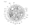
- the main rotor 21 includes an inner bore 21a coaxially assembled with the front rotor 22 and four vane grooves 21b for receiving four vanes 23 respectively and a spring 24 biasing the vanes 23 in radially outward direction. Respective vanes 23 assembled in the vane grooves 21b are extended in radially outward direction and thus form the advanced angle chambers R1 and the retarded angle chambers R2 respectively in the housing member 30.
- the main rotor 21 includes four third passages 21c in radial direction in communication with the advanced angle passage 11 at the radial inner end via the central inner bores and in communication with the advanced angle chamber R1 at the radial outer end.
- the lock pin 61 is formed in cylindrical shape with a bottom at one end. Radial inner tip portion of the lock pin 61 can be detachably supported by a lock hole 21f formed on the main rotor 21. By supplying the operation fluid to the lock hole 21f, the lock pin 61 moves in radially outward direction by overcoming the biasing force (predetermined as a small value) of the lock spring 62 and thus being retracted to be accommodated in the attaching bore 31e. As shown in Fig.
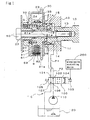
- the torsion spring S disposed between the housing member 30 and the rotor member 20 rotates the rotor member 20 towards the advanced angle side relative to the housing member 30.
- the biasing force of the torsion spring S is predetermined to be the extent of value for canceling the biasing force (i.e., derived from the spring biasing the intake valve in the closing direction) for the camshaft 10 and the rotor member 20 rotating towards the retarded angle side.
- good response can be obtained when relative rotation phase of the rotor member 20 relative to the housing member 30 is varied to the advanced angle side.
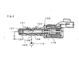
- the hydraulic pressure controlling valve 100 When the hydraulic pressure controlling valve 100 is operated under a first energization range (i.e., 1 ⁇ of Fig. 7), as shown in Fig. 3, the communication between a supply port 106 connected to an outlet opening of the oil pump 110 and the second connecting port is established and the communication between the first connecting port 101 and a discharge port 107 connected to the oil reservoir 120 is established.
- the operation fluid is supplied from the supply port 106 to the second connecting port 102 as well as discharged from the first connecting port 101 to the discharge port 107.
- the operation fluid is supplied from the oil pump 110 to the retarded angle passage 12 and the operation fluid is discharged from the advanced angle passage 11 to the oil reservoir 120.
- a part of the operation fluid supplied from the oil pump 110 to the retarded angle passage 12 leaks to the oil reservoir 120 via gap of each member (e.g., the gap between the relatively rotating rotor member 20 and the housing member 30).
- the supply port 106 communicates with the second connecting port 102 and the communication between the first connecting port 101 and the discharge port 107 is blocked.
- the operation fluid is supplied from the supply port 106 to the second connecting port 102 via a passage throttled due to the movement of the spool 104.
- a small amount of the operation fluid is supplied from the supply port 106 to the first connecting port 101 via the outer peripheral gap of the spool 104.
- the operation fluid is supplied from the oil pump 110 to the retarded angle passage 12 and to the advanced angle passage 11.
- a part of the operation fluid supplied from the oil pump 110 to the retarded angle passage 12 and the advanced angle passage 11 leaks to the oil reservoir 120 via the gap of each member (e.g., the gap between the relatively rotating torot member 20 and the housing member 30).
- variable valve timing system of the present invention when the phased is varied from the initial phase to the target advanced angle value as shown in Fig. 2, the energization of the hydraulic pressure controlling valve 100 to the solenoid 103 by the energization controlling device 200 is controlled following a predetermined control pattern shown in Fig. 7.
- the hydraulic pressure control condition of the hydraulic pressure circuit C is predetermined to vary from the initial hydraulic pressure control condition (hereinafter called a first hydraulic pressure control condition) (i.e., the condition the hydraulic pressure controlling valve 10 is operated under the first energization range shown in Fig.
- a second hydraulic pressure control condition in which the condition in which the hydraulic pressure controlling valve 100 is operated under the second energization range as shown in Fig. 4 for a predetermined time t1 (i.e., time approximately several milli seconds), and then to the hydraulic pressure control condition in which the phase can be varied to the target angle value(the phase shiftable hydraulic pressure control condition, herein after called a third hydraulic pressure control condition) in which the hydraulic pressure controlling valve 100 is operated under the range from the fifth to the third energization range.
- t1 i.e., time approximately several milli seconds
- the operation fluid can be supplied from the oil pump 110 to the retarded angle passage 12 and can be discharged from the advanced angle passage 11 to the oil reservoir 120.
- the operation fluid can be supplied from the oil pump 110 to the advanced angle passage 11 and to the retarded angle passage 12.
- the hydraulic pressure in the advanced angle chamber R1 and the lock hole 21f can be gradually increased by the operation fluid supplied to the advanced angle chamber R1 and to the lock hole 21f via the advanced angle passage 11 while maintaining the hydraulic pressure in the retarded angle chamber R2 at high level by the operation fluid supplied to the retarded angle chamber R2 via the retarded angle passage 12.
- the energization to the solenoid 103 is varied from the fifth energization range 5 ⁇ to the third energization range 3 ⁇ via the fourth energization range 4 ⁇ during a predetermined time t2 (i.e., time approximately 200 milli seconds) as viewed in Fig. 7,
- a predetermined time t2 i.e., time approximately 200 milli seconds
- relative rotation phase of the rotor member 20 relative to the housing member 30 can be adjusted and maintained at a desired phase within the range from the most retarded angle phase (i.a., the phase in which the volume of the advanced angle chamber R1 is minimum and the volume of the retarded angle chamber R2 is maximum) to the most advanced angle phase (i.e., the phase in which the volume of the advanced angle chamber R1 is maximum and the volume of the retarded angle chamber R2 is minimum).
- the valve timing of the intake valve during the drive of the combustion engine can be appropriately adjusted between the operation at the most retarded angle control condition and the most advanced angle control condition.
- variable valve timing system of the present invention during the phase being varied from the initial phase (the most retarded angle phase) to the target advanced angle value, the hydraulic pressure control condition of the hydraulic pressure circuit C is varied from the first hydraulic pressure control condition to the second hydraulic pressure control condition, and then to the third hydraulic pressure control condition.
- the lock mechanism B starts the operation to be unlocked by the operation fluid supplied from the hydraulic pressure circuit C to the lock hole 21f while the housing member 30 and the rotor member 20 are maintained at the initial phase by the operation of the stopper mechanism A1 and the control of the hydraulic pressure circuit C (i.e., the condition in which the rotational force of the torsion spring S is canceled by the hydraulic pressure of the operation fluid supplied from the hydraulic pressure circuit C to the advanced angle chamber R1 and to the retarded angle chamber R2) during the predetermined time t1.
- the hydraulic pressure circuit C i.e., the condition in which the rotational force of the torsion spring S is canceled by the hydraulic pressure of the operation fluid supplied from the hydraulic pressure circuit C to the advanced angle chamber R1 and to the retarded angle chamber R2
- the present invention is applied to the variable valve timing system equipped on the camshaft for controlling the opening and closing of the intake valve
- the present invention can be applied to another variable valve timing system equipped on the camshaft for controlling the opening and closing of the exhaust valve.
- the most advanced angle phase of the rotor member relative to the housing member is determined as the initial phase.
- the second hydraulic pressure condition is obtained by operating the hydraulic pressure control valve 100 under the second energization range for a predetermined time t1 during the phase shift from the initial phase to the target advanced angle value.
- the variable valve timing system of the present invention can be applied to obtain the second hydraulic pressure control condition by operating the hydraulic pressure controlling valve 100 under the fourth energizaition range and under the third energization range for the predetermined time t1. In those cases, the operation fluid is supplied from the pump 110 to the retarded angle passage 12 and to the advanced angle passage 11.
- variable valve timing system of the present invention irrespective of the temperature of the operation fluid flowing in the hydraulic pressure circuit C, the same operation can be obtained.
- the variable valve timing of the present invention can be applied to adjust the predetermined time t1 (shown in Fig. 7) of the control pattern to the appropriate value including zero in accordance with the temperature of the operation fluid by directly or indirectly detecting the temperature of the operation fluid flowing in the hydraulic pressure circuit C. It is preferable to determine the predetermined time t1 as short as possible because the predetermined time t1 prolong the total time for phase shift from the initial phase to the target advanced angle value.
Landscapes
- Engineering & Computer Science (AREA)
- Mechanical Engineering (AREA)
- General Engineering & Computer Science (AREA)
- Valve Device For Special Equipments (AREA)
- Output Control And Ontrol Of Special Type Engine (AREA)
Abstract
Description
Claims (15)
- A variable valve timing system comprising:a housing member provided in the driving force transmitting system for transmitting the driving force from a crankshaft of the combustion engine to a camshaft for controlling the opening and closing of either one of an intake valve or a exhaust valve of the combustion engine;a rotor member relatively rotatably assembled into the housing member and forming an advanced angle chamber and a retarded angle chamber at a vane portion in the housing member, said rotor member rotating as one unit with either one of the camshaft or the crankshaft;a torsion spring disposed between the housing member and the rotor member rotatably biasing the rotor member relative to the housing member; a lock mechanism for restricting relative rotation of the housing member and the rotor member at the initial phase of the relative rotation; anda hydraulic pressure circuit for controlling supply and discharge of the operation fluid to the advanced angle chamber and the retarded angle chamber and for controlling supply and discharge to the operation fluid of the lock mechanism;an energization controlling device for controlling the hydraulic pressure control condition of the hydraulic pressure circuit during the phase shift from the initial phase to a target angle value;wherein the hydraulic pressure control condition of the hydraulic pressure circuit is shifted from a initial hydraulic pressure control condition in which the rotor can be maintained at the initial phase and can be locked by the lock mechanism to a transitional hydraulic pressure control condition in which the rotor can be maintained at the initial phase and the lock mechanism can be released in a predetermined time, and to reach a phase shiftable hydraulic pressure control condition in which the phase can be varied to the target angle value .
- The variable valve timing system according to claim 1, wherein the hydraulic pressure supplied to the lock mechanism and in the advanced angle chamber is gradually increased while the hydraulic pressure in the retarded angle chamber is maintained at high level during the transitional second hydraulic pressure control condition.
- The variable valve timing system according to claim 1, wherein the hydraulic pressure supplied to the lock mechanism and in the retarded angle chamber is gradually increased while the hydraulic pressure in the advanced angle chamber is maintained at high level during the transitional hydraulic pressure control condition.
- The variable valve timing system according to claim 1, wherein a rotational torque towards the retarded angle side generated by the hydraulic pressure in the retarded angle chamber is either equal to or greater than the sum of a rotational torque towards the advanced angle side generated by the hydraulic pressure in the advanced angle chamber and a rotational torque towards the advanced angle side generated by a torsion spring.
- The variable valve timing system according to claim 2, wherein a rotational torque towards the retarded angle side generated by the hydraulic pressure in the retarded angle chamber is either equal to or greater than the sum of a rotational torque towards the advanced angle side generated by the hydraulic pressure in the advanced angle chamber and a rotational torque towards the advanced angle side generated by a torsion spring.
- The variable valve timing system according to claim 3, wherein a rotational torque towards the advanced angle side generated by the hydraulic pressure in the advanced angle chamber is either equal to or greater than the subtract of a rotational torque towards the retarded angle side generated by the hydraulic pressure in the retarded angle chamber and a rotational torque towards the advanced angle side generated by a torsion spring.
- The variable valve timing system according to claim 1 wherein the operation fluid can be supplied to the retarded angle chamber and the advanced angle chamber during the transitional hydraulic pressure control condition.
- A variable valve timing system for advancing and retarding a valve timing of intake and exhaust valves of a combustion engine, the system being programmed to control a hydraulic pressure control condition of a hydraulic pressure circuit in the system to shift from an initial hydraulic pressure control condition in which a rotor can be maintained at an initial phase and locked by a lock mechanism to a phase shiftable hydraulic pressure control condition in which a volume of an advanced angle chamber can be varied to meet a target advanced angle value via a transitional hydraulic pressure condition in which the rotor can be maintained at the initial phase and the lock mechanism can be released.
- A variable valve timing system for advancing and retarding a valve timing of intake and exhaust valves of a combustion engine, the system being programmed to control a hydraulic pressure control condition of a hydraulic pressure circuit in the system to shift from an initial hydraulic pressure control condition in which a rotor can be maintained at an initial phase and locked by a lock mechanism to a phase shiftable hydraulic pressure control condition in which a volume of a retarded angle chamber can be varied to meet a target retarded angle value via a transitional hydraulic pressure condition in which the rotor can be maintained at the initial phase and the lock mechanism can be released.
- The variable valve timing system according to claim 8, wherein the hydraulic pressure supplied to the lock mechanism and in the advanced angle chamber is programmed to be gradually increased while the hydraulic pressure in a retarded angle chamber is maintained at high level during the transitional hydraulic pressure control condition.
- The variable valve timing system according to claim 9, wherein the hydraulic pressure supplied to the lock mechanism and in the retarded angle chamber is programmed to be gradually increased while the hydraulic pressure in an advanced angle chamber is maintained at high level during the transitional hydraulic pressure control condition.
- The variable valve timing system according to claims 10, wherein a rotational torque towards the retarded angle side generated by the hydraulic pressure in the retarded angle chamber is programmed to be either equal to or greater than the sum of a rotational torque towards the advanced angle side generated by the hydraulic pressure in the advanced angle chamber and a rotational torque towards the advanced angle side generated by a torsion spring.
- The variable valve timing system according to claims 11, wherein a rotational torque towards the retarded angle side generated by the hydraulic pressure in the retarded angle chamber is programmed to be either equal to or greater than the sum of a rotational torque towards the advanced angle side generated by the hydraulic pressure in the advanced angle chamber and a rotational torque towards the advanced angle side generated by a torsion spring.
- The variable valve timing system according to one of claim 12, wherein the system is programmed to control the operation fluid to be supplied to the retarded angle chamber and the advanced angle chamber during the transitional hydraulic pressure control condition.
- The variable valve timing system according to one of claim 13, wherein the system is programmed to control the operation fluid to be supplied to the retarded angle chamber and the advanced angle chamber during the transitional hydraulic pressure control condition.
Applications Claiming Priority (2)
| Application Number | Priority Date | Filing Date | Title |
|---|---|---|---|
| JP2000137694A JP4240756B2 (en) | 2000-05-10 | 2000-05-10 | Valve timing control device |
| JP2000137694 | 2000-05-10 |
Publications (3)
| Publication Number | Publication Date |
|---|---|
| EP1154128A2 true EP1154128A2 (en) | 2001-11-14 |
| EP1154128A3 EP1154128A3 (en) | 2002-12-11 |
| EP1154128B1 EP1154128B1 (en) | 2007-03-07 |
Family
ID=18645426
Family Applications (1)
| Application Number | Title | Priority Date | Filing Date |
|---|---|---|---|
| EP01111345A Expired - Lifetime EP1154128B1 (en) | 2000-05-10 | 2001-05-09 | Variable valve timing system |
Country Status (4)
| Country | Link |
|---|---|
| US (1) | US6418896B2 (en) |
| EP (1) | EP1154128B1 (en) |
| JP (1) | JP4240756B2 (en) |
| DE (1) | DE60127023T2 (en) |
Cited By (4)
| Publication number | Priority date | Publication date | Assignee | Title |
|---|---|---|---|---|
| FR2840360A1 (en) * | 2002-05-29 | 2003-12-05 | Toyota Motor Co Ltd | VALVE OPENING / CLOSING TIMING CONTROL APPARATUS |
| CN1318745C (en) * | 2003-01-17 | 2007-05-30 | 株式会社日立制作所 | Valve timing control system for combustion motor |
| CN102373980A (en) * | 2010-08-24 | 2012-03-14 | 株式会社电装 | Valve timing control apparatus |
| CN112060670A (en) * | 2020-08-13 | 2020-12-11 | 邵玉刚 | Flow and pressure control device of hydraulic machine |
Families Citing this family (10)
| Publication number | Priority date | Publication date | Assignee | Title |
|---|---|---|---|---|
| US6883475B2 (en) * | 2002-04-22 | 2005-04-26 | Borgwarner Inc. | Phaser mounted DPCS (differential pressure control system) to reduce axial length of the engine |
| JP4161880B2 (en) | 2003-11-12 | 2008-10-08 | トヨタ自動車株式会社 | Valve timing control device for internal combustion engine |
| JP4553795B2 (en) * | 2005-05-24 | 2010-09-29 | 日立オートモティブシステムズ株式会社 | Valve timing control device for internal combustion engine |
| DE102008058110B4 (en) | 2008-11-18 | 2014-08-21 | Hilite Germany Gmbh | Phaser |
| JP5013323B2 (en) * | 2008-12-09 | 2012-08-29 | 株式会社デンソー | Variable valve timing control device for internal combustion engine |
| JP5240674B2 (en) * | 2009-05-12 | 2013-07-17 | 株式会社デンソー | Variable valve timing control device for internal combustion engine |
| JP2011032906A (en) * | 2009-07-30 | 2011-02-17 | Denso Corp | Variable valve timing control device for internal combustion engine |
| JP5803363B2 (en) | 2011-07-12 | 2015-11-04 | アイシン精機株式会社 | Valve timing adjustment system |
| US8714123B2 (en) * | 2012-01-18 | 2014-05-06 | Ford Global Technologies, Llc | Oil pressure modification for variable cam timing |
| JP5737238B2 (en) * | 2012-08-01 | 2015-06-17 | アイシン精機株式会社 | Valve timing adjustment system |
Family Cites Families (8)
| Publication number | Priority date | Publication date | Assignee | Title |
|---|---|---|---|---|
| EP1128028B8 (en) * | 1996-03-28 | 2012-11-07 | Aisin Seiki Kabushiki Kaisha | Valve timing control device |
| JP2947165B2 (en) * | 1996-04-12 | 1999-09-13 | トヨタ自動車株式会社 | Valve timing changing device for internal combustion engine |
| US5870983A (en) * | 1996-06-21 | 1999-02-16 | Denso Corporation | Valve timing regulation apparatus for engine |
| DE19740215B4 (en) * | 1996-09-13 | 2006-02-09 | Denso Corp., Kariya | Drehphaseneinstellvorrichtung with a synthetic resin seal |
| JP3760568B2 (en) * | 1997-06-05 | 2006-03-29 | アイシン精機株式会社 | Valve timing control device |
| JPH1150820A (en) * | 1997-08-05 | 1999-02-23 | Toyota Motor Corp | Valve timing control device for internal combustion engine |
| DE19854891C2 (en) * | 1997-11-28 | 2003-02-06 | Aisin Seiki | Valve timing control device |
| JP4147435B2 (en) * | 1998-01-30 | 2008-09-10 | アイシン精機株式会社 | Valve timing control device |
-
2000
- 2000-05-10 JP JP2000137694A patent/JP4240756B2/en not_active Expired - Lifetime
-
2001
- 2001-05-03 US US09/847,281 patent/US6418896B2/en not_active Expired - Lifetime
- 2001-05-09 DE DE60127023T patent/DE60127023T2/en not_active Expired - Lifetime
- 2001-05-09 EP EP01111345A patent/EP1154128B1/en not_active Expired - Lifetime
Cited By (5)
| Publication number | Priority date | Publication date | Assignee | Title |
|---|---|---|---|---|
| FR2840360A1 (en) * | 2002-05-29 | 2003-12-05 | Toyota Motor Co Ltd | VALVE OPENING / CLOSING TIMING CONTROL APPARATUS |
| CN1318745C (en) * | 2003-01-17 | 2007-05-30 | 株式会社日立制作所 | Valve timing control system for combustion motor |
| CN102373980A (en) * | 2010-08-24 | 2012-03-14 | 株式会社电装 | Valve timing control apparatus |
| CN102373980B (en) * | 2010-08-24 | 2014-04-09 | 株式会社电装 | Valve timing control apparatus |
| CN112060670A (en) * | 2020-08-13 | 2020-12-11 | 邵玉刚 | Flow and pressure control device of hydraulic machine |
Also Published As
| Publication number | Publication date |
|---|---|
| DE60127023T2 (en) | 2007-11-22 |
| US20010039931A1 (en) | 2001-11-15 |
| EP1154128A3 (en) | 2002-12-11 |
| DE60127023D1 (en) | 2007-04-19 |
| EP1154128B1 (en) | 2007-03-07 |
| US6418896B2 (en) | 2002-07-16 |
| JP4240756B2 (en) | 2009-03-18 |
| JP2001317381A (en) | 2001-11-16 |
Similar Documents
| Publication | Publication Date | Title |
|---|---|---|
| US6477996B2 (en) | Variable valve timing system | |
| US6439181B1 (en) | Variable valve timing system | |
| KR101084960B1 (en) | Citipager with proportional oil pressure for operating in low engine conditions with cam torsion | |
| US6779500B2 (en) | Variable valve timing control apparatus | |
| US6814038B2 (en) | Spool valve controlled VCT locking pin release mechanism | |
| US6450137B2 (en) | Variable valve timing system | |
| JP4821896B2 (en) | Valve timing control device | |
| US6408807B1 (en) | Variable valve timing system | |
| EP2278130B1 (en) | Variable valve timing control apparatus | |
| US6418896B2 (en) | Variable valve timing system | |
| US6263843B1 (en) | Valve timing control device of internal combustion engine | |
| JP4465899B2 (en) | Valve timing control device | |
| JP4503195B2 (en) | Valve timing adjustment device | |
| US6443113B1 (en) | Variable valve timing system | |
| JP3850598B2 (en) | Vane valve timing control device for internal combustion engine | |
| US6907853B2 (en) | Variable valve timing control device | |
| JP4371186B2 (en) | Valve timing control device | |
| JP4453222B2 (en) | Valve timing control device | |
| JP4389414B2 (en) | Valve timing control device | |
| JP5168389B2 (en) | Valve timing control device | |
| JP3912968B2 (en) | Valve timing control device for internal combustion engine | |
| JP2001289014A (en) | Valve timing control device |
Legal Events
| Date | Code | Title | Description |
|---|---|---|---|
| PUAI | Public reference made under article 153(3) epc to a published international application that has entered the european phase |
Free format text: ORIGINAL CODE: 0009012 |
|
| AK | Designated contracting states |
Kind code of ref document: A2 Designated state(s): AT BE CH CY DE DK ES FI FR GB GR IE IT LI LU MC NL PT SE TR |
|
| AX | Request for extension of the european patent |
Free format text: AL;LT;LV;MK;RO;SI |
|
| PUAL | Search report despatched |
Free format text: ORIGINAL CODE: 0009013 |
|
| AK | Designated contracting states |
Kind code of ref document: A3 Designated state(s): AT BE CH CY DE DK ES FI FR GB GR IE IT LI LU MC NL PT SE TR |
|
| AX | Request for extension of the european patent |
Free format text: AL;LT;LV;MK;RO;SI |
|
| 17P | Request for examination filed |
Effective date: 20021129 |
|
| AKX | Designation fees paid |
Designated state(s): DE FR GB |
|
| GRAP | Despatch of communication of intention to grant a patent |
Free format text: ORIGINAL CODE: EPIDOSNIGR1 |
|
| GRAS | Grant fee paid |
Free format text: ORIGINAL CODE: EPIDOSNIGR3 |
|
| GRAA | (expected) grant |
Free format text: ORIGINAL CODE: 0009210 |
|
| AK | Designated contracting states |
Kind code of ref document: B1 Designated state(s): DE FR GB |
|
| REG | Reference to a national code |
Ref country code: GB Ref legal event code: FG4D |
|
| REF | Corresponds to: |
Ref document number: 60127023 Country of ref document: DE Date of ref document: 20070419 Kind code of ref document: P |
|
| ET | Fr: translation filed | ||
| PLBE | No opposition filed within time limit |
Free format text: ORIGINAL CODE: 0009261 |
|
| STAA | Information on the status of an ep patent application or granted ep patent |
Free format text: STATUS: NO OPPOSITION FILED WITHIN TIME LIMIT |
|
| 26N | No opposition filed |
Effective date: 20071210 |
|
| REG | Reference to a national code |
Ref country code: GB Ref legal event code: 746 Effective date: 20120220 |
|
| REG | Reference to a national code |
Ref country code: DE Ref legal event code: R084 Ref document number: 60127023 Country of ref document: DE Effective date: 20120210 |
|
| REG | Reference to a national code |
Ref country code: FR Ref legal event code: PLFP Year of fee payment: 16 |
|
| REG | Reference to a national code |
Ref country code: FR Ref legal event code: PLFP Year of fee payment: 17 |
|
| REG | Reference to a national code |
Ref country code: FR Ref legal event code: PLFP Year of fee payment: 18 |
|
| PGFP | Annual fee paid to national office [announced via postgrant information from national office to epo] |
Ref country code: DE Payment date: 20190423 Year of fee payment: 19 |
|
| PGFP | Annual fee paid to national office [announced via postgrant information from national office to epo] |
Ref country code: FR Payment date: 20190410 Year of fee payment: 19 |
|
| PGFP | Annual fee paid to national office [announced via postgrant information from national office to epo] |
Ref country code: GB Payment date: 20190508 Year of fee payment: 19 |
|
| REG | Reference to a national code |
Ref country code: DE Ref legal event code: R119 Ref document number: 60127023 Country of ref document: DE |
|
| GBPC | Gb: european patent ceased through non-payment of renewal fee |
Effective date: 20200509 |
|
| PG25 | Lapsed in a contracting state [announced via postgrant information from national office to epo] |
Ref country code: FR Free format text: LAPSE BECAUSE OF NON-PAYMENT OF DUE FEES Effective date: 20200531 Ref country code: GB Free format text: LAPSE BECAUSE OF NON-PAYMENT OF DUE FEES Effective date: 20200509 |
|
| PG25 | Lapsed in a contracting state [announced via postgrant information from national office to epo] |
Ref country code: DE Free format text: LAPSE BECAUSE OF NON-PAYMENT OF DUE FEES Effective date: 20201201 |