EP1154126A2 - Closed circuit steam cooled turbine shroud - Google Patents
Closed circuit steam cooled turbine shroud Download PDFInfo
- Publication number
- EP1154126A2 EP1154126A2 EP01300118A EP01300118A EP1154126A2 EP 1154126 A2 EP1154126 A2 EP 1154126A2 EP 01300118 A EP01300118 A EP 01300118A EP 01300118 A EP01300118 A EP 01300118A EP 1154126 A2 EP1154126 A2 EP 1154126A2
- Authority
- EP
- European Patent Office
- Prior art keywords
- chamber
- impingement
- compartment
- cooling medium
- cooling
- Prior art date
- Legal status (The legal status is an assumption and is not a legal conclusion. Google has not performed a legal analysis and makes no representation as to the accuracy of the status listed.)
- Granted
Links
- 238000001816 cooling Methods 0.000 claims abstract description 140
- 238000011144 upstream manufacturing Methods 0.000 claims abstract description 17
- 239000002826 coolant Substances 0.000 claims description 103
- 238000004891 communication Methods 0.000 claims description 27
- 238000005192 partition Methods 0.000 claims description 25
- 238000000034 method Methods 0.000 claims description 13
- 239000007789 gas Substances 0.000 description 15
- 230000000694 effects Effects 0.000 description 3
- 230000000712 assembly Effects 0.000 description 1
- 238000000429 assembly Methods 0.000 description 1
- 239000000969 carrier Substances 0.000 description 1
- 239000000567 combustion gas Substances 0.000 description 1
- 239000000112 cooling gas Substances 0.000 description 1
- 230000001627 detrimental effect Effects 0.000 description 1
- 238000005516 engineering process Methods 0.000 description 1
- 238000010304 firing Methods 0.000 description 1
- 238000009434 installation Methods 0.000 description 1
- 238000004519 manufacturing process Methods 0.000 description 1
- 238000002844 melting Methods 0.000 description 1
- 230000008018 melting Effects 0.000 description 1
- 239000002184 metal Substances 0.000 description 1
Images


Classifications
-
- F—MECHANICAL ENGINEERING; LIGHTING; HEATING; WEAPONS; BLASTING
- F01—MACHINES OR ENGINES IN GENERAL; ENGINE PLANTS IN GENERAL; STEAM ENGINES
- F01D—NON-POSITIVE DISPLACEMENT MACHINES OR ENGINES, e.g. STEAM TURBINES
- F01D9/00—Stators
- F01D9/02—Nozzles; Nozzle boxes; Stator blades; Guide conduits, e.g. individual nozzles
- F01D9/04—Nozzles; Nozzle boxes; Stator blades; Guide conduits, e.g. individual nozzles forming ring or sector
-
- F—MECHANICAL ENGINEERING; LIGHTING; HEATING; WEAPONS; BLASTING
- F01—MACHINES OR ENGINES IN GENERAL; ENGINE PLANTS IN GENERAL; STEAM ENGINES
- F01D—NON-POSITIVE DISPLACEMENT MACHINES OR ENGINES, e.g. STEAM TURBINES
- F01D5/00—Blades; Blade-carrying members; Heating, heat-insulating, cooling or antivibration means on the blades or the members
- F01D5/12—Blades
- F01D5/14—Form or construction
- F01D5/18—Hollow blades, i.e. blades with cooling or heating channels or cavities; Heating, heat-insulating or cooling means on blades
- F01D5/187—Convection cooling
-
- F—MECHANICAL ENGINEERING; LIGHTING; HEATING; WEAPONS; BLASTING
- F05—INDEXING SCHEMES RELATING TO ENGINES OR PUMPS IN VARIOUS SUBCLASSES OF CLASSES F01-F04
- F05D—INDEXING SCHEME FOR ASPECTS RELATING TO NON-POSITIVE-DISPLACEMENT MACHINES OR ENGINES, GAS-TURBINES OR JET-PROPULSION PLANTS
- F05D2240/00—Components
- F05D2240/10—Stators
-
- F—MECHANICAL ENGINEERING; LIGHTING; HEATING; WEAPONS; BLASTING
- F05—INDEXING SCHEMES RELATING TO ENGINES OR PUMPS IN VARIOUS SUBCLASSES OF CLASSES F01-F04
- F05D—INDEXING SCHEME FOR ASPECTS RELATING TO NON-POSITIVE-DISPLACEMENT MACHINES OR ENGINES, GAS-TURBINES OR JET-PROPULSION PLANTS
- F05D2240/00—Components
- F05D2240/80—Platforms for stationary or moving blades
- F05D2240/81—Cooled platforms
-
- F—MECHANICAL ENGINEERING; LIGHTING; HEATING; WEAPONS; BLASTING
- F05—INDEXING SCHEMES RELATING TO ENGINES OR PUMPS IN VARIOUS SUBCLASSES OF CLASSES F01-F04
- F05D—INDEXING SCHEME FOR ASPECTS RELATING TO NON-POSITIVE-DISPLACEMENT MACHINES OR ENGINES, GAS-TURBINES OR JET-PROPULSION PLANTS
- F05D2260/00—Function
- F05D2260/20—Heat transfer, e.g. cooling
- F05D2260/201—Heat transfer, e.g. cooling by impingement of a fluid
-
- F—MECHANICAL ENGINEERING; LIGHTING; HEATING; WEAPONS; BLASTING
- F05—INDEXING SCHEMES RELATING TO ENGINES OR PUMPS IN VARIOUS SUBCLASSES OF CLASSES F01-F04
- F05D—INDEXING SCHEME FOR ASPECTS RELATING TO NON-POSITIVE-DISPLACEMENT MACHINES OR ENGINES, GAS-TURBINES OR JET-PROPULSION PLANTS
- F05D2260/00—Function
- F05D2260/20—Heat transfer, e.g. cooling
- F05D2260/232—Heat transfer, e.g. cooling characterized by the cooling medium
- F05D2260/2322—Heat transfer, e.g. cooling characterized by the cooling medium steam
Definitions
- the present invention relates to the cooling of turbine shrouds and, more particularly, to an apparatus for the impingement cooling of turbine shrouds as well as a system for flowing a cooling medium, in series, through several cooling cavities of a turbine shroud in a single, closed circuit.
- Shrouds in an industrial gas turbine engine are located over the tips of the bucket.
- the shrouds assist in creating the annulus that contains the hot gas path air used by the buckets to produce rotational motion and, therefore, power.
- the shrouds are used to form the gas path of the turbine section of the engine.
- advanced gas turbine designs it has been recognized that the temperature of the hot gas flowing past the turbine components could be higher then the melting temperature of the metal. It is therefore necessary to establish a cooling scheme to protect the hot gas path components during operation.
- Typical turbine shrouds are cooled by conduction, impingement cooling, film cooling or combinations of the above. More specifically, one method for cooling turbine shrouds employs an air impingement plate which has a multiplicity of holes for flowing air through the impingement plate at relatively high velocity due to a pressure difference across the plate. The high velocity air flow through the holes strikes and impinges on the component to be cooled. After striking and cooling the component, the post-impingement air finds its way to the lowest pressure sink.
- Cooling air usage in a gas turbine is very costly for performance and emissions.
- high technology engines produce high firing temperatures and the hot gas path components need to be actively cooled to be able to withstand the high gas path temperatures encountered under these circumstances.
- U.S. Patent No. 5,391,052 the disclosure of which is incorporated herein by this reference, describes apparatuses and methods for impingement cooling of turbine components, particularly turbine shrouds using steam as a cooling medium.
- U.S. Patent No. 5,480,281 the disclosure of which is incorporated herein by this reference, provides an apparatus for impingement cooling turbine shrouds in a manner to reduce cross flow effects as well as a system for flowing a cooling medium, in series, through a pair of cooling cavities of the turbine shroud in a single flow circuit. While the apparatuses and methods disclosed in these patents afford effective steam cooling of turbine shrouds, there remains a continuing need for improving turbine shroud cooling while minimizing the amount of cooling media required and reducing cross flow effects.
- One embodiment of the present invention provides an improved closed cooling flow circuit for cooling turbine shrouds which provides for flowing a cool medium through a plurality of cooling chambers defined in the cooling cavity of the shroud so as to achieve a series of impingement cooling operations to maximize the cooling of the wall of the shroud exposed to the hot gas path and to minimize detrimental cross flow effects without reducing the area that is subject to impingement cooling.
- the closed circuit cooling configuration described hereinbelow may be used with any cooling medium.
- the cooling medium is steam and thus steam will generally be referred to hereinbelow in a non-limiting manner as the cooling medium.
- the invention is embodied, therefore, in an apparatus in which steam is brought on board into the outer shroud and spilt so as to be directed to the respective inner shrouds.
- the steam or other cooling medium is impinged on the shroud inner surface opposite the hot gas path surface of the inner shroud.
- the post impingement steam flows into a second chamber of the inner shroud to again be impinged on the shroud inner surface for impingement cooling of that portion of the inner shroud.
- the flow of post impingement steam and re-impingement of the inner shroud surface is then repeated through third and fourth chambers of the inner shroud.
- the spent steam is then returned to the system for being reused in the cycle.
- the system described hereinbelow is particularly adapted for a combined cycle system installation.
- the present invention improves engine performance and reduces engine emissions while still maintaining the program requirements of part life and cost effectiveness.
- the shroud system which surrounds the buckets forming the gas path is composed of a number of outer shrouds which are the carriers of at least one inner shroud.
- one outer shroud and two inner shrouds make up one shroud assembly and forty-two (42) such shroud assemblies make up one shroud set.
- FIGURE 1 illustrates a shroud assembly 10 disposed radially outside the stage 1 buckets 12, only one of which is shown in FIGURE 1.
- the closed circuit cooling configuration described hereinbelow may be used with any cooling medium.
- the cooling medium is steam and thus steam will generally be referred to hereinbelow in a non-limiting manner as the cooling medium.
- FIGURE 2 shows in greater detail the assembly of the outer shroud 18 and first and second inner shrouds 20 in this exemplary embodiment.
- the steam inlet port is shown at 22 whereas the outlet or exit port is designated 24.
- the inlet and exit ports are formed in the outer cover to the outer shroud 18.
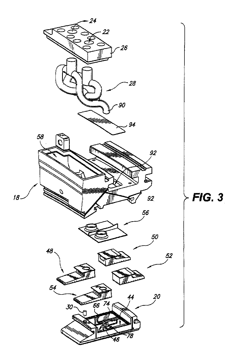
- FIGURE 3 shows this exemplary embodiment of the invention in greater detail.
- the steam inlet port 22 and steam outlet port 24 are defined in outer cover 26.
- This particular system has steam tubes or piping 28 internal to the outer shroud that interfaces between the inlet and exit ports and the inner shroud interfaces for flowing the steam to respective inner shrouds, and returning spent cooling media, as described in greater detail below.
- This piping is enclosed in the outer shroud during shroud assembly.
- FIGURE 3 Only one of the inner shrouds 20 is shown in FIGURE 3 although, as noted above, in this exemplary embodiment, two inner shrouds are associated with each outer shroud 18.
- the inner shroud is engaged with the outer shroud in a conventional manner and in this example an inner shroud anti rotation pin 30 extends therebetween.
- the inner shroud is partitioned by ribs or partition walls 32, 34, 36, 38 as shown in greater detail in FIGURE 4 to define four cooling chambers 40, 42, 44, 46.
- An impingement baffle inserts 48, 50, 52, 54 is disposed in each of these four chambers, as described in greater detail below, and an inner shroud cover plate 56 is provided to over lie the impingement baffles and to communicate with the respective cooling media tubes 28, 90 which extend through a compartment 58 therefor defined in the outer shroud 18.
- the cover plate 56 thus closes the chambers 40, 42, 44, 46 of the inner shroud 20 and controls/limits the cooling media inflow to and outflow from the inner shroud chambers.
- Each impingement baffle divides its respective cooling chamber into a first, upstream compartment, and a second, downstream compartment.
- the impingement baffle insert defines an interior space that comprises the upstream chamber.
- the second, downstream compartment is the volume of the respective chamber that surrounds the impingement baffle insert, but is predominantly defined between the impingement baffle insert and the radially inner wall of the respective chamber.
- Each impingement baffle insert has a plurality of flow openings defined therethrough for communicating cooling medium from the first compartment through those openings into the second compartment for impingement cooling of radially inner wall of the chamber; which is also the radially inner wall of the shroud assembly 10.
- steam is brought on board through an interface at the forward end of the outer shroud 18.
- the steam is then carried through the steam piping 28 and split between the two inner shrouds 20 associated with the respective outer shroud 18.
- the steam enters the first chamber 40 of the four illustrated chambers, more specifically a first, upstream compartment 60 thereof defined by the impingement baffle 48 received therewithin.
- the cooling steam is impinged through the impingement holes 62 on the bottom surface, and in this example also on the side wall, of the impingement baffle 48 and is impinged upon the inner surface of the inner shroud radially inner wall 64.
- the post impingement steam then flows from the first chamber 40 to the second chamber 42.
- the impingement baffle 48 of the first chamber is spaced from the rearward wall 32 that separates the first and second chambers 40, 42 so as to allow post impingement cooling media to flow therebetween.
- One or more apertures, such as a cooling media aperture 66 is defined in wall 32 so as to allow the flow of that post impingement cooling media into the second chamber 42.
- a cooling media inlet 68 is defined in the impingement baffle 50 of the second chamber 42 to receive the flow of cooling media from the first chamber 40 into the first, upstream compartment 70 of the second chamber that is defined therewithin. The cooling media then flows through holes 72 to be again impinged onto the inner surface of the inner shroud radially inner wall 64.
- the impingement baffle 50 of the second chamber 42 is spaced from the rib or wall 34 separating the second and third chambers 42, 44 so as to allow the post impingement cooling media to flow therebetween and then through the cutout or aperture(s) 74 defined in wall 34.
- An aperture (not shown) is defined in the impingement baffle 52 of the third chamber 44 so that the cooling media will flow into the upstream compartment of the third chamber, defined within the impingement baffle 52.
- the cooling media flows through holes 76 to again impinge on the inner shroud inner surface for further cooling thereof.
- the flow of the cooling media through the inner shroud continues as the cooling steam flows through an aperture or cutout 78 in the wall 36 disposed between the third and fourth chambers 44, 46 into the impingement baffle 54 of the fourth, and in this embodiment final, cooling chamber 46.
- the cooling media is once again impinged by flowing through holes 80, to impinge against the inner surface of the inner shroud radially inner wall.
- the spent cooling steam thereafter flows to the steam exit 82 through a gap 84 defined between the exit plate 86 and the upper wall 88 of the impingement baffle 54, as shown.
- the steam flows through the exhaust passage defined by exit tube 90 to be combined with the spent cooling media from the second inner shroud (not shown in FIGURE 4) and exits through the steam piping 28 to an interface at the forward end of the outer shroud where it is returned to the combined cycle system.
- the illustrated system has piping 28 internal to the outer shroud 18 that interfaces between the inlet and exit ports 22, 24 and the inner shroud cover plate 56.
- This piping is enclosed in the outer shroud during the assembly of the shroud fabrication.
- An access hole 92 is provided in the outer shroud to access the piping connection to the inner shroud to inspect the connection to ensure that the connection is satisfactory.
- This access has been covered by a plate 94, as shown in FIGURE 3, to complete the shroud cooling system.
Landscapes
- Engineering & Computer Science (AREA)
- Mechanical Engineering (AREA)
- General Engineering & Computer Science (AREA)
- Turbine Rotor Nozzle Sealing (AREA)
Abstract
Description
- The present invention relates to the cooling of turbine shrouds and, more particularly, to an apparatus for the impingement cooling of turbine shrouds as well as a system for flowing a cooling medium, in series, through several cooling cavities of a turbine shroud in a single, closed circuit.
- Shrouds in an industrial gas turbine engine are located over the tips of the bucket. The shrouds assist in creating the annulus that contains the hot gas path air used by the buckets to produce rotational motion and, therefore, power. Thus, the shrouds are used to form the gas path of the turbine section of the engine. In advanced gas turbine designs, it has been recognized that the temperature of the hot gas flowing past the turbine components could be higher then the melting temperature of the metal. It is therefore necessary to establish a cooling scheme to protect the hot gas path components during operation.
- Typical turbine shrouds are cooled by conduction, impingement cooling, film cooling or combinations of the above. More specifically, one method for cooling turbine shrouds employs an air impingement plate which has a multiplicity of holes for flowing air through the impingement plate at relatively high velocity due to a pressure difference across the plate. The high velocity air flow through the holes strikes and impinges on the component to be cooled. After striking and cooling the component, the post-impingement air finds its way to the lowest pressure sink.
- Cooling air usage in a gas turbine is very costly for performance and emissions. However, as noted above, high technology engines produce high firing temperatures and the hot gas path components need to be actively cooled to be able to withstand the high gas path temperatures encountered under these circumstances.
- Steam has been demonstrated to be a desired alternative cooling media for cooling gas turbine parts, particularly for combined-cycle plants. However, because steam has a higher heat capacity than the combustion gas, it is inefficient to allow coolant steam to mix with the hot gas stream. Consequently, it is desirable to maintain cooling steam inside the hot gas path components in a closed circuit. Using a closed circuit cooling system achieves the objectives of greater performance with less emissions.
- U.S. Patent No. 5,391,052, the disclosure of which is incorporated herein by this reference, describes apparatuses and methods for impingement cooling of turbine components, particularly turbine shrouds using steam as a cooling medium. U.S. Patent No. 5,480,281, the disclosure of which is incorporated herein by this reference, provides an apparatus for impingement cooling turbine shrouds in a manner to reduce cross flow effects as well as a system for flowing a cooling medium, in series, through a pair of cooling cavities of the turbine shroud in a single flow circuit. While the apparatuses and methods disclosed in these patents afford effective steam cooling of turbine shrouds, there remains a continuing need for improving turbine shroud cooling while minimizing the amount of cooling media required and reducing cross flow effects.
- One embodiment of the present invention provides an improved closed cooling flow circuit for cooling turbine shrouds which provides for flowing a cool medium through a plurality of cooling chambers defined in the cooling cavity of the shroud so as to achieve a series of impingement cooling operations to maximize the cooling of the wall of the shroud exposed to the hot gas path and to minimize detrimental cross flow effects without reducing the area that is subject to impingement cooling.
- The closed circuit cooling configuration described hereinbelow may be used with any cooling medium. However, in the presently preferred embodiment, the cooling medium is steam and thus steam will generally be referred to hereinbelow in a non-limiting manner as the cooling medium.
- The invention is embodied, therefore, in an apparatus in which steam is brought on board into the outer shroud and spilt so as to be directed to the respective inner shrouds. Within each inner shroud, the steam or other cooling medium is impinged on the shroud inner surface opposite the hot gas path surface of the inner shroud. The post impingement steam flows into a second chamber of the inner shroud to again be impinged on the shroud inner surface for impingement cooling of that portion of the inner shroud. In the presently preferred, exemplary embodiment, the flow of post impingement steam and re-impingement of the inner shroud surface is then repeated through third and fourth chambers of the inner shroud. The spent steam is then returned to the system for being reused in the cycle. The system described hereinbelow is particularly adapted for a combined cycle system installation.
- The present invention improves engine performance and reduces engine emissions while still maintaining the program requirements of part life and cost effectiveness.
- The invention will now be described in greater detail, by way of example, with reference to the drawings, in which:-
- FIGURE 1 is a schematic elevational view of a stage 1 shroud as disposed in a gas turbine;
- FIGURE 2 is a perspective view of a steam cooled shroud assembly embodying the invention;
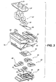
- FIGURE 3 is an exploded perspective view of the assembly of FIGURE 2; and
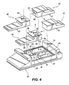
- FIGURE 4 is an exploded perspective view of the stage 1 inner shroud assembly.
-
- The shroud system which surrounds the buckets forming the gas path is composed of a number of outer shrouds which are the carriers of at least one inner shroud. In the illustrated example, one outer shroud and two inner shrouds make up one shroud assembly and forty-two (42) such shroud assemblies make up one shroud set. FIGURE 1 illustrates a
shroud assembly 10 disposed radially outside the stage 1buckets 12, only one of which is shown in FIGURE 1. Also shown in FIGURE 1 is theturbine shell interface 14,nozzle hook interface 16 and the inflow of cooling media shown by dash dot line S. As noted above, the closed circuit cooling configuration described hereinbelow may be used with any cooling medium. However, in the presently preferred embodiment the cooling medium is steam and thus steam will generally be referred to hereinbelow in a non-limiting manner as the cooling medium. - FIGURE 2 shows in greater detail the assembly of the
outer shroud 18 and first and secondinner shrouds 20 in this exemplary embodiment. The steam inlet port is shown at 22 whereas the outlet or exit port is designated 24. The inlet and exit ports are formed in the outer cover to theouter shroud 18. - FIGURE 3 shows this exemplary embodiment of the invention in greater detail. As noted above, the
steam inlet port 22 andsteam outlet port 24 are defined inouter cover 26. This particular system has steam tubes orpiping 28 internal to the outer shroud that interfaces between the inlet and exit ports and the inner shroud interfaces for flowing the steam to respective inner shrouds, and returning spent cooling media, as described in greater detail below. This piping is enclosed in the outer shroud during shroud assembly. - Only one of the
inner shrouds 20 is shown in FIGURE 3 although, as noted above, in this exemplary embodiment, two inner shrouds are associated with eachouter shroud 18. The inner shroud is engaged with the outer shroud in a conventional manner and in this example an inner shroudanti rotation pin 30 extends therebetween. The inner shroud is partitioned by ribs orpartition walls cooling chambers shroud cover plate 56 is provided to over lie the impingement baffles and to communicate with the respectivecooling media tubes compartment 58 therefor defined in theouter shroud 18. Thecover plate 56 thus closes thechambers inner shroud 20 and controls/limits the cooling media inflow to and outflow from the inner shroud chambers. - Each impingement baffle divides its respective cooling chamber into a first, upstream compartment, and a second, downstream compartment. In the illustrated embodiment the impingement baffle insert defines an interior space that comprises the upstream chamber. Furthermore, in the illustrated embodiment, the second, downstream compartment is the volume of the respective chamber that surrounds the impingement baffle insert, but is predominantly defined between the impingement baffle insert and the radially inner wall of the respective chamber. Each impingement baffle insert has a plurality of flow openings defined therethrough for communicating cooling medium from the first compartment through those openings into the second compartment for impingement cooling of radially inner wall of the chamber; which is also the radially inner wall of the
shroud assembly 10. - Thus, as illustrated, steam is brought on board through an interface at the forward end of the
outer shroud 18. The steam is then carried through thesteam piping 28 and split between the twoinner shrouds 20 associated with the respectiveouter shroud 18. In theinner shroud 20, the steam enters thefirst chamber 40 of the four illustrated chambers, more specifically a first,upstream compartment 60 thereof defined by theimpingement baffle 48 received therewithin. The cooling steam is impinged through theimpingement holes 62 on the bottom surface, and in this example also on the side wall, of theimpingement baffle 48 and is impinged upon the inner surface of the inner shroud radiallyinner wall 64. - The post impingement steam then flows from the
first chamber 40 to thesecond chamber 42. As shown, theimpingement baffle 48 of the first chamber is spaced from therearward wall 32 that separates the first andsecond chambers cooling media aperture 66 is defined inwall 32 so as to allow the flow of that post impingement cooling media into thesecond chamber 42. - As shown in FIGURE 4, a
cooling media inlet 68 is defined in theimpingement baffle 50 of thesecond chamber 42 to receive the flow of cooling media from thefirst chamber 40 into the first,upstream compartment 70 of the second chamber that is defined therewithin. The cooling media then flows throughholes 72 to be again impinged onto the inner surface of the inner shroud radiallyinner wall 64. - The
impingement baffle 50 of thesecond chamber 42 is spaced from the rib orwall 34 separating the second andthird chambers wall 34. An aperture (not shown) is defined in theimpingement baffle 52 of thethird chamber 44 so that the cooling media will flow into the upstream compartment of the third chamber, defined within theimpingement baffle 52. The cooling media flows throughholes 76 to again impinge on the inner shroud inner surface for further cooling thereof. - The flow of the cooling media through the inner shroud continues as the cooling steam flows through an aperture or
cutout 78 in thewall 36 disposed between the third andfourth chambers impingement baffle 54 of the fourth, and in this embodiment final, coolingchamber 46. The cooling media is once again impinged by flowing throughholes 80, to impinge against the inner surface of the inner shroud radially inner wall. The spent cooling steam thereafter flows to thesteam exit 82 through agap 84 defined between theexit plate 86 and theupper wall 88 of theimpingement baffle 54, as shown. The steam flows through the exhaust passage defined byexit tube 90 to be combined with the spent cooling media from the second inner shroud (not shown in FIGURE 4) and exits through the steam piping 28 to an interface at the forward end of the outer shroud where it is returned to the combined cycle system. - As mentioned above, the illustrated system has piping 28 internal to the
outer shroud 18 that interfaces between the inlet andexit ports shroud cover plate 56. This piping is enclosed in the outer shroud during the assembly of the shroud fabrication. Anaccess hole 92 is provided in the outer shroud to access the piping connection to the inner shroud to inspect the connection to ensure that the connection is satisfactory. This access has been covered by aplate 94, as shown in FIGURE 3, to complete the shroud cooling system. - For the sake of good order, various aspects of the invention are set out in the following clauses:-
- 1. Impingement cooling apparatus for a turbine shroud assembly having
inner and outer walls spaced from one another to define a cooling cavity
therebetween, comprising:
- partition walls provided in said cavity to define at least four cooling chambers within said cavity, each said cooling chamber having a cooling medium inlet and a cooling medium outlet and defining a cooling medium flow path therethrough; an impingement baffle being disposed in each said chamber to define upstream and downstream compartments therewithin, each said impingement baffle having a plurality of flow openings therethrough for communicating cooling medium between said compartments through said openings; each said upstream compartment being in flow communication with the respective cooling medium inlet and each said downstream compartment being in flow communication with the respective cooling medium outlet;
- a supply passage in communication with a first of said cooling chambers for supplying cooling medium to said upstream compartment of said first chamber for flow through the openings of the impingement baffle thereof into said downstream compartment of said first chamber for impingement cooling of said inner wall;
- an exhaust passage in communication with a fourth of said cooling chambers for exhausting post-impingement cooling medium from said downstream compartment of said fourth chamber.
- 2. An impingement cooling apparatus as in clause 1, wherein said turbine shroud assembly comprises an outer shroud and at least one inner shroud, a said cooling cavity being defined in each said inner shroud, said supply passage being defined through said outer shroud for conducting cooling medium to a cooling medium inlet of said at least one inner shroud and wherein said exhaust passage extends through said outer shroud.
- 3. An impingement cooling apparatus as in clause 1, wherein at least one of said impingement baffles comprises an impingement baffle insert defining an interior space and having an inlet for flowing cooling media into said interior space, said interior space defining said upstream compartment of said respective chamber.
- 4. An impingement cooling apparatus as in clause 1, wherein each said impingement baffle comprises an impingement baffle insert defining an interior space and having an inlet for flowing cooling media into said interior space, said interior space defining said upstream compartment of said respective chamber.
- 5. An impingement cooling apparatus as in clause 1, wherein a first said partition wall is disposed between said first cooling chamber and a second said cooling chamber, a cooling media aperture being defined in said first partition wall for flowing cooling medium from said first chamber to said second chamber, said impingement baffle disposed in said first chamber being spaced from said first partition wall so that post impingement cooling media flows between said impingement baffle and said first partition wall and through said cooling media aperture to said second chamber.
- 6. An impingement cooling apparatus as in clause 5, wherein said impingement baffle disposed in said second chamber comprises an impingement baffle insert defining an interior space and having an inlet for flowing cooling media into said interior space, said interior space defining said upstream compartment of said second chamber, said cooling media inlet of said impingement baffle of said second chamber being disposed in flow communication with said cooling media aperture in said first partition wall, whereby said post impingement cooling media flowing through said cooling media aperture in said first partition wall flows substantially solely into said interior space of said impingement baffle insert of said second chamber.
- 7. A system for cooling a turbine shroud comprising:
- a shroud housing defining a plurality of chambers;
- a first chamber of said plurality of chambers having an inlet for receiving cooling medium and a cooling medium outlet, said first chamber having an impingement baffle disposed therein to define first and second compartments therewithin, said first compartment of said first chamber being in flow communication with said inlet thereof and said second compartment of said first chamber being in flow communication with said outlet thereof; said impingement baffle having a plurality of flow openings therethrough for communicating cooling medium from said first compartment through said openings into said second compartment for impingement cooling of a wall of said first chamber;
- a second chamber of said plurality of chambers having an impingement baffle disposed therein to define first and second compartments therewithin, said first compartment of said second chamber being in flow communication with said outlet of said first chamber for receiving cooling medium from said first chamber, said impingement baffle having a plurality of flow openings therethrough for communicating cooling medium from said first compartment through said openings into said second compartment for impingement cooling of a wall of said second chamber, said second chamber having an outlet for post-impingement cooling medium to exit said second compartment thereof;
- a third chamber of said plurality of chambers having an impingement baffle disposed therein to define first and second compartments, said first compartment of said third chamber being in flow communication with said outlet of said second chamber for receiving cooling medium from said second chamber, said impingement baffle having a plurality of flow openings therethrough for communicating cooling medium from said first compartment through said openings into said second compartment for impingement cooling of a wall of said third chamber, said third chamber having an outlet for post-impingement cooling medium to exit said second compartment thereof;
- a fourth chamber of said plurality of chambers having an impingement baffle disposed therein to define first and second compartments, said first compartment of said fourth chamber being in flow communication with said outlet of said third chamber for receiving cooling medium from said third chamber, said impingement baffle having a plurality of flow openings therethrough for communicating cooling medium from said first compartment through said openings into said second compartment for impingement cooling of a wall of said fourth chamber, said fourth chamber having an outlet for post-impingement cooling medium to exit said second compartment thereof;
- an inlet port in communication with said inlet of said first chamber for flowing cooling medium thereto; and
- an exit port in communication with said outlet of said fourth chamber for exhausting post-impingement cooling medium therefrom.
- 8. A system as in clause 7, wherein said turbine shroud comprises an outer shroud and at least one inner shroud, each said inner shroud defining a said shroud housing, a supply passage being defined through said outer shroud for conducting cooling medium to said inlet of said first chamber and wherein an exhaust passage extends through said outer shroud for exhausting post-impingement flow from said outlet of said fourth chamber.
- 9. A system as in clause 7, wherein at least one of said impingement baffles comprises an impingement baffle insert defining an interior space and having an inlet for flowing cooling media into said interior space, said interior space defining said first compartment of said respective chamber.
- 10. A system as in clause 7, wherein each said impingement baffle comprises an impingement baffle insert defining an interior space and having an inlet for flowing cooling media into said interior space, said interior space defining said first compartment of said respective chamber.
- 11. A system as in clause 7, wherein a first partition wall is disposed between said first chamber and said second chamber, a cooling media aperture being defined in said first partition wall for flowing cooling medium from said first chamber to said second chamber, said impingement baffle disposed in said first chamber being spaced from said first partition wall so that post impingement cooling media flows between said impingement baffle and said first partition wall and through said cooling media aperture to said second chamber.
- 12. A system as in clause 11, wherein said impingement baffle disposed in said second chamber comprises an impingement baffle insert defining an interior space and having an inlet for flowing cooling media into said interior space, said interior space defining said first compartment of said second chamber, said cooling media inlet of said impingement baffle of said second chamber being disposed in flow communication with said second compartment of said first chamber, whereby said post impingement cooling media flows substantially solely from said second compartment of said first chamber into said interior space of said impingement baffle insert of said second chamber.
- 13. A system as in clause 7, wherein a first partition wall is disposed between said first chamber and said second chamber, a cooling media aperture being defined in said first partition wall for flowing cooling medium from said first chamber to said second chamber, and wherein said impingement baffle disposed in said second chamber comprises an impingement baffle insert defining an interior space and having an inlet for flowing cooling media into said interior space, said interior space defining said first compartment of said second chamber, said cooling media inlet of said impingement baffle of said second chamber being disposed in flow communication with said cooling media aperture in said first partition wall, whereby said post impingement cooling media flowing through said cooling media aperture in said first partition wall flows substantially solely into said interior space of said impingement baffle of second chamber.
- 14. A method of cooling a turbine shroud by cooling medium impingement
comprising the steps of:
- providing a turbine shroud having at least four cooling chambers defined therein, an inlet port for flowing cooling medium thereto, and an exit port for exhausting spent cooling medium therefrom;
- flowing cooling medium through said inlet port and into a first chamber of said plurality of chambers within the shroud;
- flowing cooling medium through a plurality of openings defined in an impingement baffle dividing the first chamber into a first compartment and a second compartment;
- directing the cooling medium flowing through said openings across said second compartment of said first chamber for impingement against a radially inner wall of the shroud to cool said wall;
- flowing post-impingement cooling medium from said first chamber through an aperture defined in a wall thereof and into a second chamber of said plurality of chambers within the shroud;
- flowing cooling medium through a plurality of openings defined in an impingement baffle dividing the second chamber into a first compartment and a second compartment;
- directing the cooling medium flowing through said openings across said second compartment of said second chamber for impingement against said radially inner wall of the shroud to cool said wall;
- flowing post-impingement cooling medium from said second chamber through an aperture defined in a wall thereof and into a third chamber of said plurality of chambers within the shroud;
- flowing cooling medium through a plurality of openings defined in an impingement baffle dividing the third chamber into a first compartment and a second compartment;
- directing the cooling medium flowing through said openings across said second compartment of said third chamber for impingement against said radially inner wall of the shroud to cool said wall;
- flowing post-impingement cooling medium from said third chamber through an aperture defined in a wall thereof and into a fourth chamber of said plurality of chambers within the shroud;
- flowing cooling medium through a plurality of openings defined in an impingement baffle dividing the fourth chamber into a first compartment and a second compartment;
- directing the cooling medium flowing through said openings across said second compartment of said fourth chamber for impingement against said radially inner wall of the shroud to cool said wall;
- flowing post-impingement cooling medium from said fourth chamber through an exit defined in a wall thereof; and
- exhausting spent cooling medium through said exit port.
- 15. A method as in
clause 14, wherein said step of providing a turbine shroud comprises providing an assembly including an outer shroud and at least one inner shroud, each said inner shroud having a said plurality of cooling chambers defined therewithin, a supply passage being defined through said outer shroud for conducting cooling medium to from said inlet port to said inner shroud, and an exhaust passage being defined through said outer shroud for exhausting post-impingement flow from said exit of said fourth chamber. - 16. A method as in
clause 14, wherein at least one of said impingement baffles comprises an impingement baffle insert defining an interior space and having an inlet for flowing cooling media into said interior space, said interior space defining said first compartment of said respective chamber. - 17. A method as in
clause 14, wherein each said impingement baffle comprises an impingement baffle insert defining an interior space and having an inlet for flowing cooling media into said interior space, said interior space defining said first compartment of said respective chamber. - 18. A method as in
clause 14, wherein a first partition wall is disposed between said first chamber and said second chamber, said aperture of said first chamber being defined in said first partition wall for flowing cooling medium from said first chamber to said second chamber, said impingement baffle disposed in said first chamber being spaced from said first partition wall so that post impingement cooling media flows between said impingement baffle and said first partition wall and through said aperture to said second chamber. - 19. A method as in
clause 14, wherein said impingement baffle disposed in said second chamber comprises an impingement baffle insert defining an interior space and having an inlet for flowing cooling media into said interior space, said interior space defining said first compartment of said second chamber, said cooling media inlet of said impingement baffle of said second chamber being disposed in flow communication with said second compartment of said first chamber, whereby said post impingement cooling media flows substantially solely from said second compartment of said first chamber into said interior space of said impingement baffle insert of second chamber. - 20. A method as in
clause 14, wherein a first partition wall is disposed between said first chamber and said second chamber, wherein said aperture of said first chamber is defined in said first partition wall for flowing cooling medium from said first chamber to said second chamber, and wherein said impingement baffle disposed in said second chamber comprises an impingement baffle insert defining an interior space and having an inlet for flowing cooling media into said interior space, said interior space defining said first compartment of said second chamber, said cooling media inlet of said impingement baffle of said second chamber being disposed in flow communication with said aperture in said first partition wall, whereby said post impingement cooling media flowing through said aperture in said first partition wall flows substantially solely into said interior space of said impingement baffle of second chamber. -
Claims (10)
- Impingement cooling apparatus for a turbine shroud assembly having inner and outer walls spaced from one another to define a cooling cavity therebetween, comprising:partition walls provided in said cavity to define at least four cooling chambers within said cavity, each said cooling chamber having a cooling medium inlet and a cooling medium outlet and defining a cooling medium flow path therethrough; an impingement baffle being disposed in each said chamber to define upstream and downstream compartments therewithin, each said impingement baffle having a plurality of flow openings therethrough for communicating cooling medium between said compartments through said openings; each said upstream compartment being in flow communication with the respective cooling medium inlet and each said downstream compartment being in flow communication with the respective cooling medium outlet;a supply passage in communication with a first of said cooling chambers for supplying cooling medium to said upstream compartment of said first chamber for flow through the openings of the impingement baffle thereof into said downstream compartment of said first chamber for impingement cooling of said inner wall;an exhaust passage in communication with a fourth of said cooling chambers for exhausting post-impingement cooling medium from said downstream compartment of said fourth chamber.
- An impingement cooling apparatus as in claim 1, wherein said turbine shroud assembly comprises an outer shroud and at least one inner shroud, a said cooling cavity being defined in each said inner shroud, said supply passage being defined through said outer shroud for conducting cooling medium to a cooling medium inlet of said at least one inner shroud and wherein said exhaust passage extends through said outer shroud.
- An impingement cooling apparatus as in claim 1 or 2, wherein at least one of said impingement baffles comprises an impingement baffle insert defining an interior space and having an inlet for flowing cooling media into said interior space, said interior space defining said upstream compartment of said respective chamber.
- An impingement cooling apparatus as in claim 1, 2 or 3, wherein each said impingement baffle comprises an impingement baffle insert defining an interior space and having an inlet for flowing cooling media into said interior space, said interior space defining said upstream compartment of said respective chamber.
- A system for cooling a turbine shroud comprising:a shroud housing defining a plurality of chambers;a first chamber of said plurality of chambers having an inlet for receiving cooling medium and a cooling medium outlet, said first chamber having an impingement baffle disposed therein to define first and second compartments therewithin, said first compartment of said first chamber being in flow communication with said inlet thereof and said second compartment of said first chamber being in flow communication with said outlet thereof; said impingement baffle having a plurality of flow openings therethrough for communicating cooling medium from said first compartment through said openings into said second compartment for impingement cooling of a wall of said first chamber;a second chamber of said plurality of chambers having an impingement baffle disposed therein to define first and second compartments therewithin, said first compartment of said second chamber being in flow communication with said outlet of said first chamber for receiving cooling medium from said first chamber, said impingement baffle having a plurality of flow openings therethrough for communicating cooling medium from said first compartment through said openings into said second compartment for impingement cooling of a wall of said second chamber, said second chamber having an outlet for post-impingement cooling medium to exit said second compartment thereof;a third chamber of said plurality of chambers having an impingement baffle disposed therein to define first and second compartments, said first compartment of said third chamber being in flow communication with said outlet of said second chamber for receiving cooling medium from said second chamber, said impingement baffle having a plurality of flow openings therethrough for communicating cooling medium from said first compartment through said openings into said second compartment for impingement cooling of a wall of said third chamber, said third chamber having an outlet for post-impingement cooling medium to exit said second compartment thereof;a fourth chamber of said plurality of chambers having an impingement baffle disposed therein to define first and second compartments, said first compartment of said fourth chamber being in flow communication with said outlet of said third chamber for receiving cooling medium from said third chamber, said impingement baffle having a plurality of flow openings therethrough for communicating cooling medium from said first compartment through said openings into said second compartment for impingement cooling of a wall of said fourth chamber, said fourth chamber having an outlet for post-impingement cooling medium to exit said second compartment thereof;an inlet port in communication with said inlet of said first chamber for flowing cooling medium thereto; andan exit port in communication with said outlet of said fourth chamber for exhausting post-impingement cooling medium therefrom.
- A system as in claim 5, wherein said turbine shroud comprises an outer shroud and at least one inner shroud, each said inner shroud defining a said shroud housing, a supply passage being defined through said outer shroud for conducting cooling medium to said inlet of said first chamber and wherein an exhaust passage extends through said outer shroud for exhausting post-impingement flow from said outlet of said fourth chamber.
- A system as in claim 5 or 6, wherein at least one of said impingement baffles comprises an impingement baffle insert defining an interior space and having an inlet for flowing cooling media into said interior space, said interior space defining said first compartment of said respective chamber.
- A method of cooling a turbine shroud by cooling medium impingement comprising the steps of:providing a turbine shroud having at least four cooling chambers defined therein, an inlet port for flowing cooling medium thereto, and an exit port for exhausting spent cooling medium therefrom;flowing cooling medium through said inlet port and into a first chamber of said plurality of chambers within the shroud;flowing cooling medium through a plurality of openings defined in an impingement baffle dividing the first chamber into a first compartment and a second compartment;directing the cooling medium flowing through said openings across said second compartment of said first chamber for impingement against a radially inner wall of the shroud to cool said wall;flowing post-impingement cooling medium from said first chamber through an aperture defined in a wall thereof and into a second chamber of said plurality of chambers within the shroud;flowing cooling medium through a plurality of openings defined in an impingement baffle dividing the second chamber into a first compartment and a second compartment;directing the cooling medium flowing through said openings across said second compartment of said second chamber for impingement against said radially inner wall of the shroud to cool said wall;flowing post-impingement cooling medium from said second chamber through an aperture defined in a wall thereof and into a third chamber of said plurality of chambers within the shroud;flowing cooling medium through a plurality of openings defined in an impingement baffle dividing the third chamber into a first compartment and a second compartment;directing the cooling medium flowing through said openings across said second compartment of said third chamber for impingement against said radially inner wall of the shroud to cool said wall;flowing post-impingement cooling medium from said third chamber through an aperture defined in a wall thereof and into a fourth chamber of said plurality of chambers within the shroud;flowing cooling medium through a plurality of openings defined in an impingement baffle dividing the fourth chamber into a first compartment and a second compartment;directing the cooling medium flowing through said openings across said second compartment of said fourth chamber for impingement against said radially inner wall of the shroud to cool said wall;flowing post-impingement cooling medium from said fourth chamber through an exit defined in a wall thereof; andexhausting spent cooling medium through said exit port.
- A method as in claim 8, wherein said step of providing a turbine shroud comprises providing an assembly including an outer shroud and at least one inner shroud, each said inner shroud having a said plurality of cooling chambers defined therewithin, a supply passage being defined through said outer shroud for conducting cooling medium to from said inlet port to said inner shroud, and an exhaust passage being defined through said outer shroud for exhausting post-impingement flow from said exit of said fourth chamber.
- A method as in claim 8 or 9, wherein at least one of said impingement baffles comprises an impingement baffle insert defining an interior space and having an inlet for flowing cooling media into said interior space, said interior space defining said first compartment of said respective chamber.
Applications Claiming Priority (2)
| Application Number | Priority Date | Filing Date | Title |
|---|---|---|---|
| US567296 | 1983-12-30 | ||
| US09/567,296 US6390769B1 (en) | 2000-05-08 | 2000-05-08 | Closed circuit steam cooled turbine shroud and method for steam cooling turbine shroud |
Publications (3)
| Publication Number | Publication Date |
|---|---|
| EP1154126A2 true EP1154126A2 (en) | 2001-11-14 |
| EP1154126A3 EP1154126A3 (en) | 2003-02-26 |
| EP1154126B1 EP1154126B1 (en) | 2007-06-13 |
Family
ID=24266572
Family Applications (1)
| Application Number | Title | Priority Date | Filing Date |
|---|---|---|---|
| EP01300118A Expired - Lifetime EP1154126B1 (en) | 2000-05-08 | 2001-01-08 | Closed circuit steam cooled turbine shroud |
Country Status (7)
| Country | Link |
|---|---|
| US (1) | US6390769B1 (en) |
| EP (1) | EP1154126B1 (en) |
| JP (1) | JP2001317306A (en) |
| KR (1) | KR100628589B1 (en) |
| AT (1) | ATE364776T1 (en) |
| CZ (1) | CZ200142A3 (en) |
| DE (1) | DE60128859T2 (en) |
Cited By (2)
| Publication number | Priority date | Publication date | Assignee | Title |
|---|---|---|---|---|
| FR2832178A1 (en) * | 2001-11-15 | 2003-05-16 | Snecma Moteurs | Gas turbine fixed ring cooler has cavities fitted with particle impact covers pierced with holes for passage of cooling air |
| WO2006029889A1 (en) * | 2004-09-17 | 2006-03-23 | Nuovo Pignone S.P.A. | Protection device for a turbine stator |
Families Citing this family (18)
| Publication number | Priority date | Publication date | Assignee | Title |
|---|---|---|---|---|
| JP4274666B2 (en) * | 2000-03-07 | 2009-06-10 | 三菱重工業株式会社 | gas turbine |
| US6832892B2 (en) | 2002-12-11 | 2004-12-21 | General Electric Company | Sealing of steam turbine bucket hook leakages using a braided rope seal |
| US6939106B2 (en) * | 2002-12-11 | 2005-09-06 | General Electric Company | Sealing of steam turbine nozzle hook leakages using a braided rope seal |
| US6899518B2 (en) | 2002-12-23 | 2005-05-31 | Pratt & Whitney Canada Corp. | Turbine shroud segment apparatus for reusing cooling air |
| US6776583B1 (en) | 2003-02-27 | 2004-08-17 | General Electric Company | Turbine bucket damper pin |
| US7063503B2 (en) * | 2004-04-15 | 2006-06-20 | Pratt & Whitney Canada Corp. | Turbine shroud cooling system |
| US7338253B2 (en) * | 2005-09-15 | 2008-03-04 | General Electric Company | Resilient seal on trailing edge of turbine inner shroud and method for shroud post impingement cavity sealing |
| US7448850B2 (en) * | 2006-04-07 | 2008-11-11 | General Electric Company | Closed loop, steam cooled turbine shroud |
| US7488157B2 (en) * | 2006-07-27 | 2009-02-10 | Siemens Energy, Inc. | Turbine vane with removable platform inserts |
| US7581924B2 (en) * | 2006-07-27 | 2009-09-01 | Siemens Energy, Inc. | Turbine vanes with airfoil-proximate cooling seam |
| US7811054B2 (en) * | 2007-05-30 | 2010-10-12 | General Electric Company | Shroud configuration having sloped seal |
| EP2159381A1 (en) * | 2008-08-27 | 2010-03-03 | Siemens Aktiengesellschaft | Turbine lead rotor holder for a gas turbine |
| US8096758B2 (en) * | 2008-09-03 | 2012-01-17 | Siemens Energy, Inc. | Circumferential shroud inserts for a gas turbine vane platform |
| US10337404B2 (en) * | 2010-03-08 | 2019-07-02 | General Electric Company | Preferential cooling of gas turbine nozzles |
| US9328623B2 (en) * | 2011-10-05 | 2016-05-03 | General Electric Company | Turbine system |
| US9404379B2 (en) * | 2013-04-02 | 2016-08-02 | General Electric Company | Gas turbine shroud assemblies |
| US11035247B2 (en) * | 2016-04-01 | 2021-06-15 | General Electric Company | Turbine apparatus and method for redundant cooling of a turbine apparatus |
| US11572801B2 (en) | 2019-09-12 | 2023-02-07 | General Electric Company | Turbine engine component with baffle |
Citations (2)
| Publication number | Priority date | Publication date | Assignee | Title |
|---|---|---|---|---|
| US5391052A (en) | 1993-11-16 | 1995-02-21 | General Electric Co. | Impingement cooling and cooling medium retrieval system for turbine shrouds and methods of operation |
| US5480281A (en) | 1994-06-30 | 1996-01-02 | General Electric Co. | Impingement cooling apparatus for turbine shrouds having ducts of increasing cross-sectional area in the direction of post-impingement cooling flow |
Family Cites Families (7)
| Publication number | Priority date | Publication date | Assignee | Title |
|---|---|---|---|---|
| US4573865A (en) * | 1981-08-31 | 1986-03-04 | General Electric Company | Multiple-impingement cooled structure |
| US5169287A (en) * | 1991-05-20 | 1992-12-08 | General Electric Company | Shroud cooling assembly for gas turbine engine |
| US5464322A (en) * | 1994-08-23 | 1995-11-07 | General Electric Company | Cooling circuit for turbine stator vane trailing edge |
| US5634766A (en) * | 1994-08-23 | 1997-06-03 | General Electric Co. | Turbine stator vane segments having combined air and steam cooling circuits |
| FR2766517B1 (en) * | 1997-07-24 | 1999-09-03 | Snecma | DEVICE FOR VENTILATION OF A TURBOMACHINE RING |
| US6146091A (en) * | 1998-03-03 | 2000-11-14 | Mitsubishi Heavy Industries, Ltd. | Gas turbine cooling structure |
| EP1124039A1 (en) * | 2000-02-09 | 2001-08-16 | General Electric Company | Impingement cooling apparatus for a gas turbine shroud system |
-
2000
- 2000-05-08 US US09/567,296 patent/US6390769B1/en not_active Expired - Lifetime
-
2001
- 2001-01-04 CZ CZ200142A patent/CZ200142A3/en unknown
- 2001-01-05 KR KR1020010000626A patent/KR100628589B1/en not_active Expired - Fee Related
- 2001-01-05 JP JP2001000296A patent/JP2001317306A/en active Pending
- 2001-01-08 AT AT01300118T patent/ATE364776T1/en not_active IP Right Cessation
- 2001-01-08 EP EP01300118A patent/EP1154126B1/en not_active Expired - Lifetime
- 2001-01-08 DE DE60128859T patent/DE60128859T2/en not_active Expired - Lifetime
Patent Citations (2)
| Publication number | Priority date | Publication date | Assignee | Title |
|---|---|---|---|---|
| US5391052A (en) | 1993-11-16 | 1995-02-21 | General Electric Co. | Impingement cooling and cooling medium retrieval system for turbine shrouds and methods of operation |
| US5480281A (en) | 1994-06-30 | 1996-01-02 | General Electric Co. | Impingement cooling apparatus for turbine shrouds having ducts of increasing cross-sectional area in the direction of post-impingement cooling flow |
Cited By (4)
| Publication number | Priority date | Publication date | Assignee | Title |
|---|---|---|---|---|
| FR2832178A1 (en) * | 2001-11-15 | 2003-05-16 | Snecma Moteurs | Gas turbine fixed ring cooler has cavities fitted with particle impact covers pierced with holes for passage of cooling air |
| WO2006029889A1 (en) * | 2004-09-17 | 2006-03-23 | Nuovo Pignone S.P.A. | Protection device for a turbine stator |
| US7559740B2 (en) | 2004-09-17 | 2009-07-14 | Nuovo Pignone S.P.A. | Protection device for a turbine stator |
| KR101253789B1 (en) * | 2004-09-17 | 2013-04-12 | 누보 피그노네 에스피에이 | Protection device for a turbine stator |
Also Published As
| Publication number | Publication date |
|---|---|
| KR20010103556A (en) | 2001-11-23 |
| EP1154126A3 (en) | 2003-02-26 |
| DE60128859T2 (en) | 2008-02-21 |
| CZ200142A3 (en) | 2001-12-12 |
| US6390769B1 (en) | 2002-05-21 |
| EP1154126B1 (en) | 2007-06-13 |
| KR100628589B1 (en) | 2006-09-26 |
| JP2001317306A (en) | 2001-11-16 |
| DE60128859D1 (en) | 2007-07-26 |
| ATE364776T1 (en) | 2007-07-15 |
Similar Documents
| Publication | Publication Date | Title |
|---|---|---|
| EP1154126B1 (en) | Closed circuit steam cooled turbine shroud | |
| EP0911486B1 (en) | Gas turbine stationary blade cooling | |
| JP3316415B2 (en) | Gas turbine cooling vane | |
| EP0690205B1 (en) | Cooling apparatus for turbine shrouds | |
| JP4659971B2 (en) | Turbine vane segment with internal cooling circuit | |
| US5762471A (en) | turbine stator vane segments having leading edge impingement cooling circuits | |
| EP1116861B1 (en) | A cooling circuit for a gas turbine bucket | |
| US5207556A (en) | Airfoil having multi-passage baffle | |
| US6132169A (en) | Turbine airfoil and methods for airfoil cooling | |
| EP1156186A2 (en) | Film cooling air pocket in a closed loop cooled airfoil | |
| EP1052374B1 (en) | Cooling circuit for steam and air-cooled turbine nozzle stage | |
| EP0698723A2 (en) | Turbine stator vane segment having closed cooling circuit | |
| US6468031B1 (en) | Nozzle cavity impingement/area reduction insert | |
| EP1149983A2 (en) | Film cooling for a closed loop cooled airfoil | |
| GB2408780A (en) | Cooling sidewalls of turbine nozzle segments | |
| US5813827A (en) | Apparatus for cooling a gas turbine airfoil | |
| WO2023171745A1 (en) | Method for cooling static vanes of gas turbine and cooling structure | |
| CN119968494A (en) | Cooling structure of shroud of turbine stator blade and manufacturing method thereof | |
| CA2258206C (en) | Configuration of cooling channels for cooling the trailing edge of gas turbine vanes |
Legal Events
| Date | Code | Title | Description |
|---|---|---|---|
| PUAI | Public reference made under article 153(3) epc to a published international application that has entered the european phase |
Free format text: ORIGINAL CODE: 0009012 |
|
| AK | Designated contracting states |
Kind code of ref document: A2 Designated state(s): AT BE CH CY DE DK ES FI FR GB GR IE IT LI LU MC NL PT SE TR |
|
| AX | Request for extension of the european patent |
Free format text: AL;LT;LV;MK;RO;SI |
|
| PUAL | Search report despatched |
Free format text: ORIGINAL CODE: 0009013 |
|
| AK | Designated contracting states |
Kind code of ref document: A3 Designated state(s): AT BE CH CY DE DK ES FI FR GB GR IE IT LI LU MC NL PT SE TR |
|
| AX | Request for extension of the european patent |
Extension state: AL LT LV MK RO SI |
|
| RIC1 | Information provided on ipc code assigned before grant |
Ipc: 7F 01D 25/12 A Ipc: 7F 01D 5/18 B |
|
| 17P | Request for examination filed |
Effective date: 20030826 |
|
| AKX | Designation fees paid |
Designated state(s): AT BE CH CY DE DK ES FI FR GB GR IE IT LI LU MC NL PT SE TR |
|
| GRAP | Despatch of communication of intention to grant a patent |
Free format text: ORIGINAL CODE: EPIDOSNIGR1 |
|
| GRAS | Grant fee paid |
Free format text: ORIGINAL CODE: EPIDOSNIGR3 |
|
| GRAA | (expected) grant |
Free format text: ORIGINAL CODE: 0009210 |
|
| AK | Designated contracting states |
Kind code of ref document: B1 Designated state(s): AT BE CH CY DE DK ES FI FR GB GR IE IT LI LU MC NL PT SE TR |
|
| REG | Reference to a national code |
Ref country code: GB Ref legal event code: FG4D |
|
| REG | Reference to a national code |
Ref country code: CH Ref legal event code: EP |
|
| REG | Reference to a national code |
Ref country code: IE Ref legal event code: FG4D |
|
| REG | Reference to a national code |
Ref country code: CH Ref legal event code: NV Representative=s name: SERVOPATENT GMBH |
|
| REF | Corresponds to: |
Ref document number: 60128859 Country of ref document: DE Date of ref document: 20070726 Kind code of ref document: P |
|
| PG25 | Lapsed in a contracting state [announced via postgrant information from national office to epo] |
Ref country code: SE Free format text: LAPSE BECAUSE OF FAILURE TO SUBMIT A TRANSLATION OF THE DESCRIPTION OR TO PAY THE FEE WITHIN THE PRESCRIBED TIME-LIMIT Effective date: 20070913 |
|
| ET | Fr: translation filed | ||
| PG25 | Lapsed in a contracting state [announced via postgrant information from national office to epo] |
Ref country code: AT Free format text: LAPSE BECAUSE OF FAILURE TO SUBMIT A TRANSLATION OF THE DESCRIPTION OR TO PAY THE FEE WITHIN THE PRESCRIBED TIME-LIMIT Effective date: 20070613 |
|
| NLV1 | Nl: lapsed or annulled due to failure to fulfill the requirements of art. 29p and 29m of the patents act | ||
| PG25 | Lapsed in a contracting state [announced via postgrant information from national office to epo] |
Ref country code: BE Free format text: LAPSE BECAUSE OF FAILURE TO SUBMIT A TRANSLATION OF THE DESCRIPTION OR TO PAY THE FEE WITHIN THE PRESCRIBED TIME-LIMIT Effective date: 20070613 |
|
| PG25 | Lapsed in a contracting state [announced via postgrant information from national office to epo] |
Ref country code: PT Free format text: LAPSE BECAUSE OF FAILURE TO SUBMIT A TRANSLATION OF THE DESCRIPTION OR TO PAY THE FEE WITHIN THE PRESCRIBED TIME-LIMIT Effective date: 20071113 Ref country code: NL Free format text: LAPSE BECAUSE OF FAILURE TO SUBMIT A TRANSLATION OF THE DESCRIPTION OR TO PAY THE FEE WITHIN THE PRESCRIBED TIME-LIMIT Effective date: 20070613 Ref country code: ES Free format text: LAPSE BECAUSE OF FAILURE TO SUBMIT A TRANSLATION OF THE DESCRIPTION OR TO PAY THE FEE WITHIN THE PRESCRIBED TIME-LIMIT Effective date: 20070924 |
|
| REG | Reference to a national code |
Ref country code: CH Ref legal event code: PFA Owner name: GENERAL ELECTRIC COMPANY Free format text: GENERAL ELECTRIC COMPANY#1 RIVER ROAD#SCHENECTADY, NY 12345 (US) -TRANSFER TO- GENERAL ELECTRIC COMPANY#1 RIVER ROAD#SCHENECTADY, NY 12345 (US) |
|
| PLBE | No opposition filed within time limit |
Free format text: ORIGINAL CODE: 0009261 |
|
| STAA | Information on the status of an ep patent application or granted ep patent |
Free format text: STATUS: NO OPPOSITION FILED WITHIN TIME LIMIT |
|
| PG25 | Lapsed in a contracting state [announced via postgrant information from national office to epo] |
Ref country code: GR Free format text: LAPSE BECAUSE OF FAILURE TO SUBMIT A TRANSLATION OF THE DESCRIPTION OR TO PAY THE FEE WITHIN THE PRESCRIBED TIME-LIMIT Effective date: 20070914 Ref country code: DK Free format text: LAPSE BECAUSE OF FAILURE TO SUBMIT A TRANSLATION OF THE DESCRIPTION OR TO PAY THE FEE WITHIN THE PRESCRIBED TIME-LIMIT Effective date: 20070613 |
|
| 26N | No opposition filed |
Effective date: 20080314 |
|
| PG25 | Lapsed in a contracting state [announced via postgrant information from national office to epo] |
Ref country code: MC Free format text: LAPSE BECAUSE OF NON-PAYMENT OF DUE FEES Effective date: 20080131 |
|
| PG25 | Lapsed in a contracting state [announced via postgrant information from national office to epo] |
Ref country code: IE Free format text: LAPSE BECAUSE OF NON-PAYMENT OF DUE FEES Effective date: 20080108 |
|
| PG25 | Lapsed in a contracting state [announced via postgrant information from national office to epo] |
Ref country code: FI Free format text: LAPSE BECAUSE OF FAILURE TO SUBMIT A TRANSLATION OF THE DESCRIPTION OR TO PAY THE FEE WITHIN THE PRESCRIBED TIME-LIMIT Effective date: 20070613 |
|
| PG25 | Lapsed in a contracting state [announced via postgrant information from national office to epo] |
Ref country code: CY Free format text: LAPSE BECAUSE OF FAILURE TO SUBMIT A TRANSLATION OF THE DESCRIPTION OR TO PAY THE FEE WITHIN THE PRESCRIBED TIME-LIMIT Effective date: 20070613 |
|
| PG25 | Lapsed in a contracting state [announced via postgrant information from national office to epo] |
Ref country code: LU Free format text: LAPSE BECAUSE OF NON-PAYMENT OF DUE FEES Effective date: 20080108 |
|
| PG25 | Lapsed in a contracting state [announced via postgrant information from national office to epo] |
Ref country code: TR Free format text: LAPSE BECAUSE OF FAILURE TO SUBMIT A TRANSLATION OF THE DESCRIPTION OR TO PAY THE FEE WITHIN THE PRESCRIBED TIME-LIMIT Effective date: 20070613 |
|
| PGFP | Annual fee paid to national office [announced via postgrant information from national office to epo] |
Ref country code: DE Payment date: 20110127 Year of fee payment: 11 Ref country code: FR Payment date: 20110301 Year of fee payment: 11 Ref country code: CH Payment date: 20110125 Year of fee payment: 11 Ref country code: IT Payment date: 20110125 Year of fee payment: 11 |
|
| PGFP | Annual fee paid to national office [announced via postgrant information from national office to epo] |
Ref country code: GB Payment date: 20110125 Year of fee payment: 11 |
|
| REG | Reference to a national code |
Ref country code: CH Ref legal event code: PL |
|
| GBPC | Gb: european patent ceased through non-payment of renewal fee |
Effective date: 20120108 |
|
| REG | Reference to a national code |
Ref country code: FR Ref legal event code: ST Effective date: 20120928 |
|
| PG25 | Lapsed in a contracting state [announced via postgrant information from national office to epo] |
Ref country code: CH Free format text: LAPSE BECAUSE OF NON-PAYMENT OF DUE FEES Effective date: 20120131 Ref country code: DE Free format text: LAPSE BECAUSE OF NON-PAYMENT OF DUE FEES Effective date: 20120801 Ref country code: LI Free format text: LAPSE BECAUSE OF NON-PAYMENT OF DUE FEES Effective date: 20120131 Ref country code: GB Free format text: LAPSE BECAUSE OF NON-PAYMENT OF DUE FEES Effective date: 20120108 |
|
| REG | Reference to a national code |
Ref country code: DE Ref legal event code: R119 Ref document number: 60128859 Country of ref document: DE Effective date: 20120801 |
|
| PG25 | Lapsed in a contracting state [announced via postgrant information from national office to epo] |
Ref country code: IT Free format text: LAPSE BECAUSE OF NON-PAYMENT OF DUE FEES Effective date: 20120108 |
|
| PG25 | Lapsed in a contracting state [announced via postgrant information from national office to epo] |
Ref country code: FR Free format text: LAPSE BECAUSE OF NON-PAYMENT OF DUE FEES Effective date: 20120131 |
|
| PGFP | Annual fee paid to national office [announced via postgrant information from national office to epo] |
Ref country code: ES Payment date: 20120827 Year of fee payment: 11 |