EP1154088A2 - A grid system for a suspended ceiling - Google Patents
A grid system for a suspended ceiling Download PDFInfo
- Publication number
- EP1154088A2 EP1154088A2 EP01850082A EP01850082A EP1154088A2 EP 1154088 A2 EP1154088 A2 EP 1154088A2 EP 01850082 A EP01850082 A EP 01850082A EP 01850082 A EP01850082 A EP 01850082A EP 1154088 A2 EP1154088 A2 EP 1154088A2
- Authority
- EP
- European Patent Office
- Prior art keywords
- grid system
- profile
- girder
- web
- runners
- Prior art date
- Legal status (The legal status is an assumption and is not a legal conclusion. Google has not performed a legal analysis and makes no representation as to the accuracy of the status listed.)
- Granted
Links
- 125000006850 spacer group Chemical group 0.000 claims description 9
- 230000037431 insertion Effects 0.000 claims description 3
- 238000003780 insertion Methods 0.000 claims description 3
- 238000010276 construction Methods 0.000 description 2
- 239000002184 metal Substances 0.000 description 2
- 229910000639 Spring steel Inorganic materials 0.000 description 1
- 238000009825 accumulation Methods 0.000 description 1
- 230000001154 acute effect Effects 0.000 description 1
- 239000011324 bead Substances 0.000 description 1
- 238000005452 bending Methods 0.000 description 1
- 230000001419 dependent effect Effects 0.000 description 1
- 230000000994 depressogenic effect Effects 0.000 description 1
- 239000002657 fibrous material Substances 0.000 description 1
- 239000011491 glass wool Substances 0.000 description 1
- 230000001788 irregular Effects 0.000 description 1
- 238000004519 manufacturing process Methods 0.000 description 1
Images

Classifications
-
- E—FIXED CONSTRUCTIONS
- E04—BUILDING
- E04B—GENERAL BUILDING CONSTRUCTIONS; WALLS, e.g. PARTITIONS; ROOFS; FLOORS; CEILINGS; INSULATION OR OTHER PROTECTION OF BUILDINGS
- E04B9/00—Ceilings; Construction of ceilings, e.g. false ceilings; Ceiling construction with regard to insulation
- E04B9/06—Ceilings; Construction of ceilings, e.g. false ceilings; Ceiling construction with regard to insulation characterised by constructional features of the supporting construction, e.g. cross section or material of framework members
- E04B9/12—Connections between non-parallel members of the supporting construction
- E04B9/16—Connections between non-parallel members of the supporting construction the members lying in different planes
-
- E—FIXED CONSTRUCTIONS
- E04—BUILDING
- E04B—GENERAL BUILDING CONSTRUCTIONS; WALLS, e.g. PARTITIONS; ROOFS; FLOORS; CEILINGS; INSULATION OR OTHER PROTECTION OF BUILDINGS
- E04B9/00—Ceilings; Construction of ceilings, e.g. false ceilings; Ceiling construction with regard to insulation
- E04B9/06—Ceilings; Construction of ceilings, e.g. false ceilings; Ceiling construction with regard to insulation characterised by constructional features of the supporting construction, e.g. cross section or material of framework members
- E04B9/065—Ceilings; Construction of ceilings, e.g. false ceilings; Ceiling construction with regard to insulation characterised by constructional features of the supporting construction, e.g. cross section or material of framework members comprising supporting beams having a folded cross-section
-
- E—FIXED CONSTRUCTIONS
- E04—BUILDING
- E04B—GENERAL BUILDING CONSTRUCTIONS; WALLS, e.g. PARTITIONS; ROOFS; FLOORS; CEILINGS; INSULATION OR OTHER PROTECTION OF BUILDINGS
- E04B9/00—Ceilings; Construction of ceilings, e.g. false ceilings; Ceiling construction with regard to insulation
- E04B9/06—Ceilings; Construction of ceilings, e.g. false ceilings; Ceiling construction with regard to insulation characterised by constructional features of the supporting construction, e.g. cross section or material of framework members
- E04B9/12—Connections between non-parallel members of the supporting construction
- E04B9/122—Connections between non-parallel members of the supporting construction one member passing through the other member, both members laying at least partly in the same plane
-
- E—FIXED CONSTRUCTIONS
- E04—BUILDING
- E04B—GENERAL BUILDING CONSTRUCTIONS; WALLS, e.g. PARTITIONS; ROOFS; FLOORS; CEILINGS; INSULATION OR OTHER PROTECTION OF BUILDINGS
- E04B9/00—Ceilings; Construction of ceilings, e.g. false ceilings; Ceiling construction with regard to insulation
- E04B9/22—Connection of slabs, panels, sheets or the like to the supporting construction
- E04B9/24—Connection of slabs, panels, sheets or the like to the supporting construction with the slabs, panels, sheets or the like positioned on the upperside of, or held against the underside of the horizontal flanges of the supporting construction or accessory means connected thereto
- E04B9/26—Connection of slabs, panels, sheets or the like to the supporting construction with the slabs, panels, sheets or the like positioned on the upperside of, or held against the underside of the horizontal flanges of the supporting construction or accessory means connected thereto by means of snap action of elastically deformable elements held against the underside of the supporting construction
Definitions
- This invention relates to a grid system for a suspended ceiling of the kind comprising mutually spaced main runners of inverted T-profile suspended by means of hangers at the web of the T-profile, the flanges of the T-profile forming support surfaces for tiles, apertures punched at regular spacing in the web of the T-profile registering transversely of the main runners, and mutually spaced cross spacers engaging the main runners and defining the spacing therebetween.
- the tiles demountably supported by the grid system conceal this system, the linear joints between adjacent tiles being visible as a rectangular pattern on the lower side of the ceiling.
- Grid systems of the kind referred to above are marketed by Ecophon AB, Hyllinge, Sweden, under the trade mark Focus D.
- the main runners in this prior art grid system are of a reliable construction and are used also in other grid systems marketed by Ecophon AB. They are manufactured in large quantities, which keeps the price of such runners at a low level.
- the apertures in the web of the T-profile are punched with great accuracy.
- the spacers comprise L-profiles forming slots in one flange thereof to receive the main runners therein. Each spacer spans the distance between two adjacent main runners only and is located in an arbitrary displaced position along the main runners. No means are provided in order to fix the spacers in the position that has been chosen.
- US-A-4,089,146 discloses a grid system for a suspended ceiling with asymmetric main runners comprising rather elaborate box profiles.
- the main runners each form a flange for supporting a tile at one edge thereof and are combined with separate cross bars supporting the tile at two other edges thereof.
- Spacers of V-shaped cross section are mounted on the main runners receiving the box profile in a notch in the spacer.
- Prior art grid systems of the kind referred to above do not provide the rigidity that is necessary in order to maintain by accuracy the regularity and the right-angled shape of the rectangular pattern formed by the tiles. It follows that the lines formed at the joints between adjacent tiles at the lower side of the ceiling may vary in width and linearity, and that the tiles eventually may be slightly displaced in relation to each other after mounting, which may afford to the ceiling an unpleasant appearance.
- a primary object of the invention is to overcome said problem and to provide a grid system of the kind referred to above which rigidly supports the tiles in a rectangular pattern and maintains the tiles in such pattern in order to secure a permanently attractive appearance of the ceiling.
- cross spacers each consist of a channeled girder opening upwards and extending over several main runners along registering apertures therein the web of the T-profile being received in slots in the bottom and side walls of the channeled girder, and each girder is fixedly connected with the runners by fastening elements engaging the apertures therein.
- the grid system for a suspended ceiling disclosed in the drawings comprises main runners 10 of inverted T-profile which are of a wellknown construction.
- Each runner is made of a strip of a metal sheet blank which is double folded to form the web 11 of the T-profile of double metal sheet layers which are bent perpendicularly outwards at opposite sides of the web to form the flanges 12 of the T-profile at one longitudinal edge of the web.
- the edges of the flanges 12 are folded over to form a stiffening edge bead.
- the web forms a stiffening hollow portion 13 along the other longitudinal edge of the web.
- Vertical slots 14, FIG. 4 are punched in the web 11 and are mutually spaced at regular intervals, defined by great accuracy, in the longitudinal direction of the runner.
- circular apertures 15 are punched at regular intervals.
- the main runners 10 extend in parallel mutually spaced in the transverse direction thereof and with the slots in register in the transverse direction of the runners.
- the runners are fixedly secured in this position by cross girders 16 comprising channel profiles with a bottom 17 and side walls 18 which form outwardly angled edge flanges 19, FIG. 4, so that the cross girders are very stiff against bending.
- the bottom 17 is slightly V-shaped.
- the cross girder forms slots 20 which extend through the bottom and partly into the side walls of the cross girder and are mutually spaced at intervals which are defined by great accuracy.
- Each cross girder extends over several main runners and is engaged with each runner at a slot the hollow edge portion of the main runner being inserted into the slot and has tight fit therein.
- the slot is flared in the bottom 17 as shown at 21 in FIG 3 in order to facilitate the insertion of the main runner into the slot.
- the cross girder is located along registering slots 14 in the main runners and are fixedly connected with the main runners by means of split pins 22 which are inserted at one limb 22A thereof into a slot 14 said limb engaging the bottom 17 centrally thereof, while the other limb 22B engages the main runner at the edge of the web 11.
- Cross girders are distributed along the main runners at suitable intervals.
- the grid system consisting of the main runners 10 and the cross girders 16 is suspended from the building structure by means of adjustable hangers 23 which are engaged with the main runners at the slots 14 or at the apertures 15 and are secured in the building structure in which the suspended ceiling is mounted.
- the ceiling is also secured to the walls of the building structure, by means of brackets 24 connected with the cross girders 16, and brackets 25 connected with the main runners 10.
- the grid system constructed and suspended as described above provides a very sturdy and rigid support for the tiles, which affords great dimensional accuracy to the ceiling and maintains the rectangularity of the system.
- the grid system described has been developed for supporting acoustic tiles 26 having a core of fiber material such as glass wool but can be used with tiles of any type.
- the tiles 26 has at one edge a narrow shoulder 27 and at the opposite edge a wider shoulder 27' which continues into a slot 28.
- the edges are slightly chamfered at 29.
- the tile is supported at the shoulder 27 on one flange 12 of a runner 10 while the other flange 12 of an adjacent runner 10 is inserted into the slot 28.
- the shoulder 27' covers substantially totally the lower side of the flanges 12. Adjacent tiles abut each other at the edges.
- the grid system is thus completely concealed by the tiles mounted in the grid system.
- the tiles can easily be mounted and demounted by slightly lifting the edge forming the shoulder 27 and then displacing the tile so that the flange is pushed into or out of, respectively, the slot 28.
- All tiles should have a modular size but at the walls it may be necessary to cut the tiles to another size as shown in FIGS 1 and 2 at 26' and 26", and these tiles must have a short measure. They are supported by trim bars 31 secured to the walls of the building structure.
- the linearity of the lines defining the rectangular pattern on the lower side of the suspended ceiling by the butt joints between the edges 30 may be disturbed, when several tiles are located in a row along the main runners, due to manufacturing tolerances of the tiles or due to the fact that the tiles 26' which deviate from the modular size cannot be cut to the necessary dimensions with the accuracy applied in the factory to tiles of modular size.
- the invention provides the stop clip 32 disclosed in FIGS 5 to 7 in the drawings.
- the stop clip is made of spring steel. It is T-shaped and comprises a U-shaped stem 33 with a web 34 and limbs 35 projecting at one end of the stem beyond the web and angled in opposite directions to form flanges 36. At the upper and lower edges of the limbs 35 flaps 37 are punched from the limbs and project on the outside thereof at acute angle towards the adjacent flanges 36 with the tips of the flaps slightly spaced from the flanges.
- the stop clip as described can be placed in a main runner by inserting the stem 33 in a slot 14 where two adjacent tiles abut each other. At the insertion the flaps 37 will be resiliently depressed and then will spring back to latchingly engage behind the web of the runner so that the stop clip will be securely fastened to the runner.
- the tiles 26' in a row may be disposed to close to the wall so that the gap between the tiles 26' and the adjoining tiles 16 will be too wide, but the tiles 26 in the row are fixedly positioned by the clips. If the tiles 26 have a minimum tolerance, this tolerance will be equalized at each clip so that accumulation of the tolerance along the row, affording an irregular appearance to the lower face of the ceiling, will be avoided.
Landscapes
- Engineering & Computer Science (AREA)
- Architecture (AREA)
- Physics & Mathematics (AREA)
- Electromagnetism (AREA)
- Civil Engineering (AREA)
- Structural Engineering (AREA)
- Finishing Walls (AREA)
- Residential Or Office Buildings (AREA)
Abstract

Description
- This invention relates to a grid system for a suspended ceiling of the kind comprising mutually spaced main runners of inverted T-profile suspended by means of hangers at the web of the T-profile, the flanges of the T-profile forming support surfaces for tiles, apertures punched at regular spacing in the web of the T-profile registering transversely of the main runners, and mutually spaced cross spacers engaging the main runners and defining the spacing therebetween.
- The tiles demountably supported by the grid system conceal this system, the linear joints between adjacent tiles being visible as a rectangular pattern on the lower side of the ceiling.
- Grid systems of the kind referred to above are marketed by Ecophon AB, Hyllinge, Sweden, under the trade mark Focus D. The main runners in this prior art grid system are of a reliable construction and are used also in other grid systems marketed by Ecophon AB. They are manufactured in large quantities, which keeps the price of such runners at a low level. The apertures in the web of the T-profile are punched with great accuracy. The spacers comprise L-profiles forming slots in one flange thereof to receive the main runners therein. Each spacer spans the distance between two adjacent main runners only and is located in an arbitrary displaced position along the main runners. No means are provided in order to fix the spacers in the position that has been chosen.
- US-A-4,089,146 discloses a grid system for a suspended ceiling with asymmetric main runners comprising rather elaborate box profiles. The main runners each form a flange for supporting a tile at one edge thereof and are combined with separate cross bars supporting the tile at two other edges thereof. Spacers of V-shaped cross section are mounted on the main runners receiving the box profile in a notch in the spacer.
- Prior art grid systems of the kind referred to above do not provide the rigidity that is necessary in order to maintain by accuracy the regularity and the right-angled shape of the rectangular pattern formed by the tiles. It follows that the lines formed at the joints between adjacent tiles at the lower side of the ceiling may vary in width and linearity, and that the tiles eventually may be slightly displaced in relation to each other after mounting, which may afford to the ceiling an unpleasant appearance.
- A primary object of the invention is to overcome said problem and to provide a grid system of the kind referred to above which rigidly supports the tiles in a rectangular pattern and maintains the tiles in such pattern in order to secure a permanently attractive appearance of the ceiling.
- This object is achieved by the characterizing features of the invention as defined in claim 1 according to which the cross spacers each consist of a channeled girder opening upwards and extending over several main runners along registering apertures therein the web of the T-profile being received in slots in the bottom and side walls of the channeled girder, and each girder is fixedly connected with the runners by fastening elements engaging the apertures therein.
- The dependent claims define advantageous embodiments of the invention.
- The invention will be described in more detail with reference to the accompanying drawings which disclose an illustrative embodiment of the invention and wherein
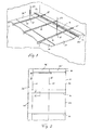
- FIG 1 is a fragmentary perspective view of a suspended ceiling with a concealed supporting grid system according to the invention,
- FIG 2 is a plan view of the grid system with tiles showing the lay-out thereof,
- FIG 3 is a cross sectional view along line III-III in FIG 2,
- FIG 4 is a cross sectional view along line IV-IV in Fig 2,
- FIG 5 is a plan view of a stop clip, and
- FIGS 6 and 7 are a perspective views of the stop clip in FIG 5 from opposite sides.
-
- The grid system for a suspended ceiling disclosed in the drawings comprises
main runners 10 of inverted T-profile which are of a wellknown construction. Each runner is made of a strip of a metal sheet blank which is double folded to form theweb 11 of the T-profile of double metal sheet layers which are bent perpendicularly outwards at opposite sides of the web to form theflanges 12 of the T-profile at one longitudinal edge of the web. The edges of theflanges 12 are folded over to form a stiffening edge bead. The web forms a stiffeninghollow portion 13 along the other longitudinal edge of the web. -
Vertical slots 14, FIG. 4, are punched in theweb 11 and are mutually spaced at regular intervals, defined by great accuracy, in the longitudinal direction of the runner. In thehollow portion 13 alsocircular apertures 15 are punched at regular intervals. - The
main runners 10 extend in parallel mutually spaced in the transverse direction thereof and with the slots in register in the transverse direction of the runners. The runners are fixedly secured in this position bycross girders 16 comprising channel profiles with abottom 17 andside walls 18 which form outwardlyangled edge flanges 19, FIG. 4, so that the cross girders are very stiff against bending. Thebottom 17 is slightly V-shaped. The cross girder formsslots 20 which extend through the bottom and partly into the side walls of the cross girder and are mutually spaced at intervals which are defined by great accuracy. Each cross girder extends over several main runners and is engaged with each runner at a slot the hollow edge portion of the main runner being inserted into the slot and has tight fit therein. The slot is flared in thebottom 17 as shown at 21 in FIG 3 in order to facilitate the insertion of the main runner into the slot. The cross girder is located along registeringslots 14 in the main runners and are fixedly connected with the main runners by means ofsplit pins 22 which are inserted at onelimb 22A thereof into aslot 14 said limb engaging thebottom 17 centrally thereof, while the other limb 22B engages the main runner at the edge of theweb 11. Cross girders are distributed along the main runners at suitable intervals. - The grid system consisting of the
main runners 10 and thecross girders 16 is suspended from the building structure by means ofadjustable hangers 23 which are engaged with the main runners at theslots 14 or at theapertures 15 and are secured in the building structure in which the suspended ceiling is mounted. The ceiling is also secured to the walls of the building structure, by means ofbrackets 24 connected with thecross girders 16, andbrackets 25 connected with themain runners 10. - The grid system constructed and suspended as described above provides a very sturdy and rigid support for the tiles, which affords great dimensional accuracy to the ceiling and maintains the rectangularity of the system.
- The grid system described has been developed for supporting
acoustic tiles 26 having a core of fiber material such as glass wool but can be used with tiles of any type. As shown in the drawings thetiles 26 has at one edge a narrow shoulder 27 and at the opposite edge a wider shoulder 27' which continues into aslot 28. At the lower side of the tile the edges are slightly chamfered at 29. The tile is supported at the shoulder 27 on oneflange 12 of arunner 10 while theother flange 12 of anadjacent runner 10 is inserted into theslot 28. Then, the shoulder 27' covers substantially totally the lower side of theflanges 12. Adjacent tiles abut each other at the edges. The grid system is thus completely concealed by the tiles mounted in the grid system. The tiles can easily be mounted and demounted by slightly lifting the edge forming the shoulder 27 and then displacing the tile so that the flange is pushed into or out of, respectively, theslot 28. - At the edges 30 perpendicular to the edges forming the shoulders 27 and 27', respectively, adjacent tiles join each other edge to edge.
- All tiles should have a modular size but at the walls it may be necessary to cut the tiles to another size as shown in FIGS 1 and 2 at 26' and 26", and these tiles must have a short measure. They are supported by
trim bars 31 secured to the walls of the building structure. - When the tiles have been engaged with the main runners at
flanges 12 and are displaced along the runners in order to be brought into abutting relationship at the edges, the linearity of the lines defining the rectangular pattern on the lower side of the suspended ceiling by the butt joints between the edges 30 may be disturbed, when several tiles are located in a row along the main runners, due to manufacturing tolerances of the tiles or due to the fact that the tiles 26' which deviate from the modular size cannot be cut to the necessary dimensions with the accuracy applied in the factory to tiles of modular size. This means that the regularity of the rectangular pattern aimed at by providing a rigid rectangular grid system as proposed according to the invention will be lost. In order to overcome this disadvantage the invention provides thestop clip 32 disclosed in FIGS 5 to 7 in the drawings. The stop clip is made of spring steel. It is T-shaped and comprises aU-shaped stem 33 with aweb 34 andlimbs 35 projecting at one end of the stem beyond the web and angled in opposite directions to formflanges 36. At the upper and lower edges of thelimbs 35flaps 37 are punched from the limbs and project on the outside thereof at acute angle towards theadjacent flanges 36 with the tips of the flaps slightly spaced from the flanges. - The stop clip as described can be placed in a main runner by inserting the
stem 33 in aslot 14 where two adjacent tiles abut each other. At the insertion theflaps 37 will be resiliently depressed and then will spring back to latchingly engage behind the web of the runner so that the stop clip will be securely fastened to the runner. By inserting stop clips at suitable intervals corresponding to a desired number of tiles and particularly between the tiles 26' and the adjoiningtiles 26 the influence on the linearity of the lines formed at the edges running perpendicularly to themain runners 10 on the lower side of the ceiling will be eliminated or minimized. The tiles 26' in a row may be disposed to close to the wall so that the gap between the tiles 26' and the adjoiningtiles 16 will be too wide, but thetiles 26 in the row are fixedly positioned by the clips. If thetiles 26 have a minimum tolerance, this tolerance will be equalized at each clip so that accumulation of the tolerance along the row, affording an irregular appearance to the lower face of the ceiling, will be avoided.
Claims (7)
- A grid system for a suspended ceiling comprising mutually spaced main runners (10) of T-profile suspended by means of hangers (23) at the web (11) of the T-profile, the flanges (12) of the T-profile forming support surfaces for tiles (26), apertures (14) punched at regular spacing in the web of the T-profile registering transversely of the main runners , and mutually spaced cross spacers (16) engaging the main runners and defining the spacing therebetween, characterized in that the cross spacers each consist of a channeled girder (16) opening upwards and extending over several main runners (10) along registering apertures (14) therein the web (11) of the T-profile being received in slots (20) in the bottom (17) and side walls (18) of the channeled girder, and that each girder (16)is fixedly connected with the runners (10) by fastening elements (22) engaging the apertures (14) therein.
- The grid system of claim 1 wherein the channeled girder (16) comprises a bottom (17) and two side walls (18) and wherein said fastening elements each comprise a split pin (22) having two limbs one (22A) of which is passed through the aperture (14) and engages the bottom (17) of the channeled girder while the other limb (22B) engages the upper edge of the web (11) of a main runner (10).
- The grid system of claim 2 wherein the bottom (17) of the channeled girder (16) forms a longitudinally extending central depression.
- The grid system of claim 3 wherein the bottom (17) of the cross girder (16) is slightly V-shaped.
- The grid system of any of claims 1 to 4 wherein a stop clip (32) is inserted in one of said apertures (14) in the main runners (10) at the joint between two adjacent tiles (26) supported by the grid system.
- The grid system of claim 5 wherein the stop clip (32) is T-shaped the stem (33) of the T being constructed for insertion through the aperture (14) with the cross bar (36) of the T located on one side of the main runner (10).
- The grid system of claim 6 wherein the stop clip (32) forms latching flaps (37) on the stem (33) of the T for engagement with the opposite side of the main runner (10).
Applications Claiming Priority (3)
| Application Number | Priority Date | Filing Date | Title |
|---|---|---|---|
| SE0001740 | 2000-05-09 | ||
| SE0001740A SE521523C2 (en) | 2000-05-09 | 2000-05-09 | Grid system for suspended ceiling has cross girder having bottom and side walls provided with slots in which web is received, and which is fixed to main runners by slit pins engaging vertical slots |
| US09/603,920 US6318042B1 (en) | 2000-05-09 | 2000-06-26 | Grid system for a suspended ceiling |
Publications (3)
| Publication Number | Publication Date |
|---|---|
| EP1154088A2 true EP1154088A2 (en) | 2001-11-14 |
| EP1154088A3 EP1154088A3 (en) | 2001-12-12 |
| EP1154088B1 EP1154088B1 (en) | 2005-09-07 |
Family
ID=26655105
Family Applications (1)
| Application Number | Title | Priority Date | Filing Date |
|---|---|---|---|
| EP01850082A Expired - Lifetime EP1154088B1 (en) | 2000-05-09 | 2001-05-08 | A grid system for a suspended ceiling |
Country Status (2)
| Country | Link |
|---|---|
| US (1) | US6318042B1 (en) |
| EP (1) | EP1154088B1 (en) |
Cited By (4)
| Publication number | Priority date | Publication date | Assignee | Title |
|---|---|---|---|---|
| EP2472022A1 (en) | 2010-12-28 | 2012-07-04 | Saint-Gobain Ecophon AB | A grid system for a suspended ceiling |
| CN105297985A (en) * | 2015-11-03 | 2016-02-03 | 中山市施丹建材有限公司 | Ceiling decoration frame |
| CN106121121A (en) * | 2016-08-31 | 2016-11-16 | 中山市施丹建材有限公司 | A kind of Combined type suspended ceiling |
| CN115234008A (en) * | 2022-08-30 | 2022-10-25 | 徐红伟 | FRP keel dry-hanging ceramic tile installation method |
Families Citing this family (36)
| Publication number | Priority date | Publication date | Assignee | Title |
|---|---|---|---|---|
| US20020112424A1 (en) * | 2001-02-22 | 2002-08-22 | Vib Inc. | Suspended ceiling support structure |
| WO2003102326A1 (en) * | 2002-04-04 | 2003-12-11 | Herman Miller, Inc. | Seiling system |
| US6729096B1 (en) | 2002-09-09 | 2004-05-04 | Aaon Inc. | System for installing suspended ceiling |
| US6971210B2 (en) | 2002-12-19 | 2005-12-06 | Owens Corning Fiberglas Technology, Inc. | Accessible ceiling grid system |
| US7152383B1 (en) * | 2003-04-10 | 2006-12-26 | Eps Specialties Ltd., Inc. | Joining of foam core panels |
| US7752821B2 (en) * | 2004-10-27 | 2010-07-13 | Chicago Metallic Corporation | Suspended ceiling system |
| US7578107B2 (en) * | 2005-12-02 | 2009-08-25 | Worthington Armstrong Venture | Suspended ceiling segment |
| US8596008B2 (en) * | 2007-06-08 | 2013-12-03 | Awi Licensing Company | Canopy system and group suspension system therefore |
| GB2456328A (en) | 2008-01-11 | 2009-07-15 | Usg Interiors Inc | Grid members for a suspended ceiling and methods of making same |
| USD668352S1 (en) | 2008-01-11 | 2012-10-02 | Usg Interiors, Llc | Suspended ceiling wall angle |
| US20090188175A1 (en) * | 2008-01-25 | 2009-07-30 | Waters James R | Cantilevered ceiling system |
| US20100064618A1 (en) * | 2008-09-15 | 2010-03-18 | Certainteed Corporation | Ceiling tile and edge suspension system |
| USD601006S1 (en) | 2008-09-15 | 2009-09-29 | Certainteed Corporation | Modified ceiling tile edge support clip |
| USD603692S1 (en) | 2008-09-15 | 2009-11-10 | Certainteed Corporation | Ceiling tile edge support clip |
| USD663047S1 (en) | 2009-02-19 | 2012-07-03 | Certainteed Corporation | Siding panel having grooved ends |
| USD616735S1 (en) | 2009-02-19 | 2010-06-01 | Certainteed Corporation | Installation clip for a siding panel |
| US20110078970A1 (en) * | 2009-10-01 | 2011-04-07 | Certainteed Corporation | Ceiling tile and edge suspension system |
| IL205989A0 (en) | 2010-02-16 | 2010-12-30 | Yaakov Vakhnin | Apparatus for securing ceiling panels |
| US8327591B2 (en) | 2010-03-24 | 2012-12-11 | Wilkinson Jr Edgar L | Overhead panel and installation system |
| US8733053B2 (en) * | 2011-06-13 | 2014-05-27 | Arktura Llc | System and method for a supported architectural design |
| US9163402B2 (en) * | 2011-06-13 | 2015-10-20 | Arktura Llc | Suspended architectural structure |
| EP2998457B1 (en) | 2014-09-19 | 2017-10-25 | Saint-Gobain Ecophon AB | Methods and tile for use in a false ceiling or wall and a false ceiling or wall |
| US9273465B1 (en) * | 2014-09-29 | 2016-03-01 | Awi Licensing Company | Ceiling system |
| US10113317B1 (en) | 2015-04-16 | 2018-10-30 | Gordon Sales, Inc. | Apparatus and method for hanging architectural panels with concealed attachment points |
| US9771718B1 (en) | 2016-10-07 | 2017-09-26 | Tate Access Floors Leasing, Inc. | Strut with non-structural infill |
| CA3100942A1 (en) * | 2018-05-24 | 2019-11-28 | Armstrong World Industries, Inc. | Ceiling system |
| CA3048391A1 (en) * | 2018-07-04 | 2020-01-04 | Hunter Douglas Industries B.V. | Ceiling system |
| US10612236B1 (en) * | 2018-11-29 | 2020-04-07 | AES Clean Technology, Inc. | Non-walkable clean room ceiling, mounting system, and method |
| CA3201069A1 (en) | 2020-12-11 | 2022-06-16 | Armstrong World Industries, Inc. | Overhead grid assembly, bracket member thereof, and ceiling system including the same |
| MX2023006893A (en) | 2020-12-11 | 2023-06-26 | Armstrong World Ind Inc | Panel assembly for a suspended ceiling system, corner bracket thereof, and related methods. |
| CN113775109B (en) * | 2021-08-23 | 2023-04-07 | 上海蓝天房屋装饰工程有限公司 | Airport assembly type ceiling system and construction method thereof |
| US12031327B1 (en) | 2022-08-29 | 2024-07-09 | Gordon Sales, Inc. | Suspended ceiling grid hanging system |
| US12421723B2 (en) * | 2023-05-03 | 2025-09-23 | Stephen McElwee | Ceiling system |
| CN117552563B (en) * | 2023-11-17 | 2026-06-30 | 北京佰地建院装饰工程设计有限公司 | Nonlinear assembled metal grid curtain wall |
| CN117905218A (en) * | 2024-01-25 | 2024-04-19 | 广州康普顿至高建材有限公司 | Ventilating suspended ceiling |
| WO2025193916A1 (en) * | 2024-03-14 | 2025-09-18 | Xo Structure Corporation | Anti-thermal bridging suspended ceiling system |
Citations (1)
| Publication number | Priority date | Publication date | Assignee | Title |
|---|---|---|---|---|
| US4089146A (en) | 1976-05-06 | 1978-05-16 | Vincent Martinez | Suspended ceiling |
Family Cites Families (9)
| Publication number | Priority date | Publication date | Assignee | Title |
|---|---|---|---|---|
| US3031042A (en) * | 1960-10-27 | 1962-04-24 | Drackett Jack William Robert | Ceiling construction |
| US3287874A (en) * | 1963-08-05 | 1966-11-29 | K S H Plastics Inc | Channel grid members with t-rail and hanger bracket |
| US3321882A (en) * | 1964-05-13 | 1967-05-30 | K S H Plastics Inc | Ceiling and elements thereof |
| DK133480B (en) * | 1973-08-29 | 1976-05-24 | Finn Andersen | Underroft. |
| US4545165A (en) * | 1983-08-15 | 1985-10-08 | Integrated Ceilings Inc. | Modular monolithic ceiling grid system |
| GB8509345D0 (en) * | 1985-04-11 | 1985-05-15 | Hunter Douglas Ind Bv | Grid ceiling |
| US6103360A (en) | 1998-01-09 | 2000-08-15 | Armstrong World Industries, Inc. | High light reflectance and durable ceiling board coating |
| US6047517A (en) * | 1998-03-30 | 2000-04-11 | 3244 Corporation | Hanger for hanging electrical fixture from suspended ceiling |
| US6077593A (en) | 1998-04-17 | 2000-06-20 | Armstrong World Industries, Inc. | Durable edge ceiling board |
-
2000
- 2000-06-26 US US09/603,920 patent/US6318042B1/en not_active Expired - Lifetime
-
2001
- 2001-05-08 EP EP01850082A patent/EP1154088B1/en not_active Expired - Lifetime
Patent Citations (1)
| Publication number | Priority date | Publication date | Assignee | Title |
|---|---|---|---|---|
| US4089146A (en) | 1976-05-06 | 1978-05-16 | Vincent Martinez | Suspended ceiling |
Cited By (4)
| Publication number | Priority date | Publication date | Assignee | Title |
|---|---|---|---|---|
| EP2472022A1 (en) | 2010-12-28 | 2012-07-04 | Saint-Gobain Ecophon AB | A grid system for a suspended ceiling |
| CN105297985A (en) * | 2015-11-03 | 2016-02-03 | 中山市施丹建材有限公司 | Ceiling decoration frame |
| CN106121121A (en) * | 2016-08-31 | 2016-11-16 | 中山市施丹建材有限公司 | A kind of Combined type suspended ceiling |
| CN115234008A (en) * | 2022-08-30 | 2022-10-25 | 徐红伟 | FRP keel dry-hanging ceramic tile installation method |
Also Published As
| Publication number | Publication date |
|---|---|
| EP1154088A3 (en) | 2001-12-12 |
| US6318042B1 (en) | 2001-11-20 |
| EP1154088B1 (en) | 2005-09-07 |
Similar Documents
| Publication | Publication Date | Title |
|---|---|---|
| EP1154088B1 (en) | A grid system for a suspended ceiling | |
| EP1154089B1 (en) | Ceiling tile | |
| US5046294A (en) | Perimeter clip | |
| US3013644A (en) | V-track ceiling structure | |
| EP2126238B1 (en) | Ceiling suspension system | |
| US4494350A (en) | Aluminum suspension system | |
| EP1160389B1 (en) | Suspended curved ceiling system | |
| AU643410B2 (en) | Trim system for suspension ceilings | |
| CA2354884C (en) | Wall system | |
| US5154031A (en) | Suspended ceiling system and connector clip therefor | |
| US4696142A (en) | Suspension ceiling with snap-up panels | |
| US5195289A (en) | Trim system for suspension ceilings | |
| CA2672419C (en) | Suspended ceiling system | |
| US4525973A (en) | Suspended ceiling system | |
| US4364215A (en) | Suspended ceiling assembly and stabilizer bar therefor | |
| EP0115415B1 (en) | Clip for a suspended ceiling | |
| US3841048A (en) | Concealed grid system | |
| CN106661883A (en) | Suspended ceiling grid system | |
| GB1600887A (en) | Suspension of gypsum board panels | |
| US4021986A (en) | Modular ceiling framework | |
| US9879424B1 (en) | Torsion spring panel bars and construction method | |
| US4696141A (en) | Suspended ceiling having a concealed suspension grid and lay-in metal panels supported thereon | |
| US4513557A (en) | Clip for use with runner and runner assembly including the clip | |
| CA2533247C (en) | Cross panel | |
| US4483116A (en) | Ceiling system with ceiling conversion strip |
Legal Events
| Date | Code | Title | Description |
|---|---|---|---|
| PUAI | Public reference made under article 153(3) epc to a published international application that has entered the european phase |
Free format text: ORIGINAL CODE: 0009012 |
|
| PUAL | Search report despatched |
Free format text: ORIGINAL CODE: 0009013 |
|
| AK | Designated contracting states |
Kind code of ref document: A2 Designated state(s): AT BE CH CY DE DK ES FI FR GB GR IE IT LI LU MC NL PT SE TR |
|
| AX | Request for extension of the european patent |
Free format text: AL;LT;LV;MK;RO;SI |
|
| AK | Designated contracting states |
Kind code of ref document: A3 Designated state(s): AT BE CH CY DE DK ES FI FR GB GR IE IT LI LU MC NL PT SE TR |
|
| AX | Request for extension of the european patent |
Free format text: AL;LT;LV;MK;RO;SI |
|
| 17P | Request for examination filed |
Effective date: 20020511 |
|
| AKX | Designation fees paid |
Free format text: AT BE CH CY DE DK ES FI FR GB GR IE IT LI LU MC NL PT SE TR |
|
| GRAP | Despatch of communication of intention to grant a patent |
Free format text: ORIGINAL CODE: EPIDOSNIGR1 |
|
| GRAS | Grant fee paid |
Free format text: ORIGINAL CODE: EPIDOSNIGR3 |
|
| GRAA | (expected) grant |
Free format text: ORIGINAL CODE: 0009210 |
|
| AK | Designated contracting states |
Kind code of ref document: B1 Designated state(s): AT BE CH CY DE DK ES FI FR GB GR IE IT LI LU MC NL PT SE TR |
|
| PG25 | Lapsed in a contracting state [announced via postgrant information from national office to epo] |
Ref country code: IT Free format text: LAPSE BECAUSE OF FAILURE TO SUBMIT A TRANSLATION OF THE DESCRIPTION OR TO PAY THE FEE WITHIN THE PRESCRIBED TIME-LIMIT;WARNING: LAPSES OF ITALIAN PATENTS WITH EFFECTIVE DATE BEFORE 2007 MAY HAVE OCCURRED AT ANY TIME BEFORE 2007. THE CORRECT EFFECTIVE DATE MAY BE DIFFERENT FROM THE ONE RECORDED. Effective date: 20050907 Ref country code: AT Free format text: LAPSE BECAUSE OF FAILURE TO SUBMIT A TRANSLATION OF THE DESCRIPTION OR TO PAY THE FEE WITHIN THE PRESCRIBED TIME-LIMIT Effective date: 20050907 Ref country code: BE Free format text: LAPSE BECAUSE OF FAILURE TO SUBMIT A TRANSLATION OF THE DESCRIPTION OR TO PAY THE FEE WITHIN THE PRESCRIBED TIME-LIMIT Effective date: 20050907 Ref country code: LI Free format text: LAPSE BECAUSE OF FAILURE TO SUBMIT A TRANSLATION OF THE DESCRIPTION OR TO PAY THE FEE WITHIN THE PRESCRIBED TIME-LIMIT Effective date: 20050907 Ref country code: NL Free format text: LAPSE BECAUSE OF FAILURE TO SUBMIT A TRANSLATION OF THE DESCRIPTION OR TO PAY THE FEE WITHIN THE PRESCRIBED TIME-LIMIT Effective date: 20050907 Ref country code: CH Free format text: LAPSE BECAUSE OF FAILURE TO SUBMIT A TRANSLATION OF THE DESCRIPTION OR TO PAY THE FEE WITHIN THE PRESCRIBED TIME-LIMIT Effective date: 20050907 Ref country code: FI Free format text: LAPSE BECAUSE OF FAILURE TO SUBMIT A TRANSLATION OF THE DESCRIPTION OR TO PAY THE FEE WITHIN THE PRESCRIBED TIME-LIMIT Effective date: 20050907 |
|
| REG | Reference to a national code |
Ref country code: GB Ref legal event code: FG4D |
|
| REG | Reference to a national code |
Ref country code: CH Ref legal event code: EP |
|
| REG | Reference to a national code |
Ref country code: IE Ref legal event code: FG4D |
|
| REF | Corresponds to: |
Ref document number: 60113182 Country of ref document: DE Date of ref document: 20051013 Kind code of ref document: P |
|
| PG25 | Lapsed in a contracting state [announced via postgrant information from national office to epo] |
Ref country code: GR Free format text: LAPSE BECAUSE OF FAILURE TO SUBMIT A TRANSLATION OF THE DESCRIPTION OR TO PAY THE FEE WITHIN THE PRESCRIBED TIME-LIMIT Effective date: 20051207 Ref country code: SE Free format text: LAPSE BECAUSE OF FAILURE TO SUBMIT A TRANSLATION OF THE DESCRIPTION OR TO PAY THE FEE WITHIN THE PRESCRIBED TIME-LIMIT Effective date: 20051207 Ref country code: DK Free format text: LAPSE BECAUSE OF FAILURE TO SUBMIT A TRANSLATION OF THE DESCRIPTION OR TO PAY THE FEE WITHIN THE PRESCRIBED TIME-LIMIT Effective date: 20051207 |
|
| PG25 | Lapsed in a contracting state [announced via postgrant information from national office to epo] |
Ref country code: ES Free format text: LAPSE BECAUSE OF FAILURE TO SUBMIT A TRANSLATION OF THE DESCRIPTION OR TO PAY THE FEE WITHIN THE PRESCRIBED TIME-LIMIT Effective date: 20051218 |
|
| PG25 | Lapsed in a contracting state [announced via postgrant information from national office to epo] |
Ref country code: PT Free format text: LAPSE BECAUSE OF FAILURE TO SUBMIT A TRANSLATION OF THE DESCRIPTION OR TO PAY THE FEE WITHIN THE PRESCRIBED TIME-LIMIT Effective date: 20060207 |
|
| NLV1 | Nl: lapsed or annulled due to failure to fulfill the requirements of art. 29p and 29m of the patents act | ||
| REG | Reference to a national code |
Ref country code: CH Ref legal event code: PL |
|
| ET | Fr: translation filed | ||
| PG25 | Lapsed in a contracting state [announced via postgrant information from national office to epo] |
Ref country code: GB Free format text: LAPSE BECAUSE OF NON-PAYMENT OF DUE FEES Effective date: 20060508 Ref country code: IE Free format text: LAPSE BECAUSE OF NON-PAYMENT OF DUE FEES Effective date: 20060508 |
|
| PG25 | Lapsed in a contracting state [announced via postgrant information from national office to epo] |
Ref country code: MC Free format text: LAPSE BECAUSE OF NON-PAYMENT OF DUE FEES Effective date: 20060531 |
|
| PLBI | Opposition filed |
Free format text: ORIGINAL CODE: 0009260 |
|
| PLAX | Notice of opposition and request to file observation + time limit sent |
Free format text: ORIGINAL CODE: EPIDOSNOBS2 |
|
| 26 | Opposition filed |
Opponent name: ROCKWOOL INTERNATIONAL A/S Effective date: 20060606 |
|
| PLBB | Reply of patent proprietor to notice(s) of opposition received |
Free format text: ORIGINAL CODE: EPIDOSNOBS3 |
|
| GBPC | Gb: european patent ceased through non-payment of renewal fee |
Effective date: 20060508 |
|
| REG | Reference to a national code |
Ref country code: IE Ref legal event code: MM4A |
|
| REG | Reference to a national code |
Ref country code: GB Ref legal event code: 728V |
|
| REG | Reference to a national code |
Ref country code: GB Ref legal event code: S28 Effective date: 20080604 |
|
| PG25 | Lapsed in a contracting state [announced via postgrant information from national office to epo] |
Ref country code: TR Free format text: LAPSE BECAUSE OF FAILURE TO SUBMIT A TRANSLATION OF THE DESCRIPTION OR TO PAY THE FEE WITHIN THE PRESCRIBED TIME-LIMIT Effective date: 20050907 Ref country code: LU Free format text: LAPSE BECAUSE OF NON-PAYMENT OF DUE FEES Effective date: 20060508 |
|
| PLCK | Communication despatched that opposition was rejected |
Free format text: ORIGINAL CODE: EPIDOSNREJ1 |
|
| PLAB | Opposition data, opponent's data or that of the opponent's representative modified |
Free format text: ORIGINAL CODE: 0009299OPPO |
|
| PG25 | Lapsed in a contracting state [announced via postgrant information from national office to epo] |
Ref country code: CY Free format text: LAPSE BECAUSE OF FAILURE TO SUBMIT A TRANSLATION OF THE DESCRIPTION OR TO PAY THE FEE WITHIN THE PRESCRIBED TIME-LIMIT Effective date: 20050907 |
|
| PLBN | Opposition rejected |
Free format text: ORIGINAL CODE: 0009273 |
|
| STAA | Information on the status of an ep patent application or granted ep patent |
Free format text: STATUS: OPPOSITION REJECTED |
|
| 27O | Opposition rejected |
Effective date: 20080717 |
|
| PGFP | Annual fee paid to national office [announced via postgrant information from national office to epo] |
Ref country code: DE Payment date: 20130506 Year of fee payment: 13 Ref country code: GB Payment date: 20130508 Year of fee payment: 13 |
|
| PGFP | Annual fee paid to national office [announced via postgrant information from national office to epo] |
Ref country code: FR Payment date: 20130605 Year of fee payment: 13 |
|
| REG | Reference to a national code |
Ref country code: DE Ref legal event code: R119 Ref document number: 60113182 Country of ref document: DE |
|
| GBPC | Gb: european patent ceased through non-payment of renewal fee |
Effective date: 20140508 |
|
| REG | Reference to a national code |
Ref country code: FR Ref legal event code: ST Effective date: 20150130 |
|
| REG | Reference to a national code |
Ref country code: DE Ref legal event code: R119 Ref document number: 60113182 Country of ref document: DE Effective date: 20141202 |
|
| PG25 | Lapsed in a contracting state [announced via postgrant information from national office to epo] |
Ref country code: DE Free format text: LAPSE BECAUSE OF NON-PAYMENT OF DUE FEES Effective date: 20141202 |
|
| PG25 | Lapsed in a contracting state [announced via postgrant information from national office to epo] |
Ref country code: FR Free format text: LAPSE BECAUSE OF NON-PAYMENT OF DUE FEES Effective date: 20140602 Ref country code: GB Free format text: LAPSE BECAUSE OF NON-PAYMENT OF DUE FEES Effective date: 20140508 |