EP1153825A2 - Articulated vehicle - Google Patents
Articulated vehicle Download PDFInfo
- Publication number
- EP1153825A2 EP1153825A2 EP01109185A EP01109185A EP1153825A2 EP 1153825 A2 EP1153825 A2 EP 1153825A2 EP 01109185 A EP01109185 A EP 01109185A EP 01109185 A EP01109185 A EP 01109185A EP 1153825 A2 EP1153825 A2 EP 1153825A2
- Authority
- EP
- European Patent Office
- Prior art keywords
- vehicle
- coupling member
- front part
- rear part
- connecting means
- Prior art date
- Legal status (The legal status is an assumption and is not a legal conclusion. Google has not performed a legal analysis and makes no representation as to the accuracy of the status listed.)
- Withdrawn
Links
- 230000008878 coupling Effects 0.000 claims abstract description 54
- 238000010168 coupling process Methods 0.000 claims abstract description 54
- 238000005859 coupling reaction Methods 0.000 claims abstract description 54
- 238000005266 casting Methods 0.000 claims abstract description 13
- 238000000034 method Methods 0.000 claims description 10
- 239000000463 material Substances 0.000 claims description 6
- 229910001141 Ductile iron Inorganic materials 0.000 claims description 5
- 238000004519 manufacturing process Methods 0.000 claims description 5
- 238000003754 machining Methods 0.000 claims description 4
- 230000005540 biological transmission Effects 0.000 claims description 3
- 230000010355 oscillation Effects 0.000 description 7
- XEEYBQQBJWHFJM-UHFFFAOYSA-N Iron Chemical compound [Fe] XEEYBQQBJWHFJM-UHFFFAOYSA-N 0.000 description 2
- 229910000831 Steel Inorganic materials 0.000 description 2
- 238000005495 investment casting Methods 0.000 description 2
- 238000007528 sand casting Methods 0.000 description 2
- 239000010959 steel Substances 0.000 description 2
- 238000003466 welding Methods 0.000 description 2
- 229910001018 Cast iron Inorganic materials 0.000 description 1
- 229910052742 iron Inorganic materials 0.000 description 1
- 238000012986 modification Methods 0.000 description 1
- 230000004048 modification Effects 0.000 description 1
- 239000004576 sand Substances 0.000 description 1
Images

Classifications
-
- B—PERFORMING OPERATIONS; TRANSPORTING
- B62—LAND VEHICLES FOR TRAVELLING OTHERWISE THAN ON RAILS
- B62D—MOTOR VEHICLES; TRAILERS
- B62D53/00—Tractor-trailer combinations; Road trains
- B62D53/02—Tractor-trailer combinations; Road trains comprising a uniaxle tractor unit and a uniaxle trailer unit
- B62D53/025—Comprising a transmission shaft passing through the coupling joints
- B62D53/026—With all wheels powered
Definitions
- This invention relates to an articulated vehicle, more particularly, to a vehicle, such as a dump truck, having front and rear parts which are coupled together to permit of articulation about generally vertically and generally horizontal axes.
- the coupling member includes a body which is made in two parts, which are fastened together by a plurality of bolts, or by welding, for examples.
- UK patent application GB2333748 discloses a coupling member having a body in which two parts are bolted together. Making the body in two parts permits the two parts to be made from two different materials and facilitates handling of the two parts, but providing an adequately strong connection between the two can be expensive.
- an articulated vehicle including a front and a rear part, and a coupling member which connects the front part to the rear part, and is adapted to permit of articulation of the front part with respect to the rear part about a generally vertical axis whilst also permitting movement of the rear part with respect to the front part about a generally horizontal axis, characterised in that the coupling member includes a body made as a unitary casting.
- the step of welding or bolting together the two parts of the coupling body is avoided, and, notwithstanding handling of the unitary casting, for example for finishing machining, may be more difficult, the cost of manufacturing the coupling member may be reduced.
- the body may be cast in cast, iron, ductile iron, austempered ductile iron, or a suitable steel.
- the coupling body may be cast using a disposable mould casting method such as sand casting or investment casting.
- a disposable mould casting method such as sand casting or investment casting.
- the casting method is selected to produce a component which requires minimum machining to achieve the required tolerance and surface finish.
- the coupling body may include a first connecting means including at least one articulation bearing part, each articulation bearing part being pivotally connected to the front or rear part of the vehicle to permit of articulation of the front or rear part of the vehicle with respect to the coupling body about the generally vertical axis.
- the first connecting means may include two articulation bearing parts, the two articulation bearing parts being provided at two opposite sides of the first connecting means, and positioned on the generally vertical axis.
- the coupling body may also include a second connecting means, the second connecting means being generally cylindrical and engaged with a corresponding cylindrical support member of the rear or front support part of the vehicle, the support member being rigidly connected to the rear or front part of the vehicle and being adapted to permit of movement of the rear or front part with respect to the coupling body about a generally horizontal axis.
- the front part of the vehicle may include an engine and a driver's cab, the engine being positioned towards the front of the front part and the driver's cab towards the rear of the front part.
- the rear part of the vehicle may include a load carrying space.
- the load carrying space may be provided within an open topped container which is pivotally connected to a frame of the rear section, in order to facilitate tipping of material out of the container.
- a drive shaft may be provided to transmit power from the engine to at least one pair of rear wheels provided on the rear part of the vehicle via a transmission means, and the drive shaft may extend through the coupling member along the generally horizontal axis.
- a coupling member adapted to connect a front part of an articulated vehicle to a rear part of an articulated vehicle and to permit of articulation of the front part of the vehicle with respect to the rear part about a generally vertical axis and movement of the rear part of the vehicle with respect to the front part about a generally horizontal axis, characterised in that the coupling member includes a body made as a unitary casting.
- a coupling member according to the second aspect of the invention characterised in that the method includes the step of casting a body of the coupling member in one piece.
- the method may also include the step of machining a first connecting means of the coupling member to produce at least one articulation bearing part by means of which the first connecting means may be pivotally connected to the front or rear part of the vehicle.
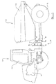
- FIGURE 1 is an illustration of a side view of an articulated vehicle according to the inventions.
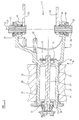
- FIGURE 2 is an illustration of a longitudinal section through a coupling member of the articulated vehicle of Figure 1.
- FIGURE 3 is an end view on the arrow C of Figure 2.
- an articulated vehicle 10 specifically a dump truck, which includes a front part 11 and a rear part 12.
- the front pail 11 includes a driver's cab 13 and an engine 14, the engine 14 being located towards the front of the front part 11 and the driver's cab 13 being located towards the rear of the front part 11.
- the rear section includes a load carrying space 15, which is provided within an open topped container.
- the container 15 is pivotally connected to the remainder of the rear part 12 to facilitate tipping of material out of the container.
- the front 11 and rear 12 pails of the vehicle 10 are connected together by means of a coupling member 16, which is adapted to permit of articulation of the front part 11 with respect to the rear part 12 about a generally vertical axis A, whilst also permitting movement of the rear part 12 with respect to the front part 11 about a generally horizontal axis B.
- the coupling member 16 has a body 30 which is made as a single unitary cast component.
- the body 30 is cast using a disposable mould casting method such as sand or investment casting, and is made from a material chosen to achieve the necessary strength and stiffness etc, such as cast iron, ductile iron, austempered ductile iron or a suitable steel.
- the body 30 includes a first connecting means 17 which in this example is adapted to be connected to the front part 11 of the vehicle 10, and a second connecting means 18 which is adapted to be connected to the rear part 12 of the vehicle 10.
- the first connecting means 17 includes a pair of spaced apart articulation bearing parts 19, 20, as shown in Figures 2 and 3, each of which includes an aperture 21, 22 centred along the generally vertical axis A.
- the apertures 21, 22 may be machined from the body 30 of the coupling member 16, or they may be provided within the coupling member 16 as cast. Alternatively, apertures 21, 22 provided in the coupling member 16 as cast, may also be machined to alter the dimensions of or to finish the apertures 21, 22.
- Each aperture 21, 22 receives a pivot pin 23, 24 about which the bearing parts 19, 20 may rotate, the pivot pins 23, 24 being connected to the front part 11 of the vehicle 10, by means of articulation support members 25, 26.
- Each articulation support member 25, 26 extends from the front part 11 of the vehicle 10, and includes an aperture in which the respective pivot pin 23, 24 is received.
- the coupling member 16 is pivotally connected to the front part 11 of the vehicle 10, to permit of rotation of the coupling member 16, and hence the rear part 12 of the vehicle 10, with respect to the front part 11 of the vehicle 10 about the generally vertical axis A.
- Each articulation bearing part 19, 20 is provided with an articulation bearing insert 27, 28 which provides a suitable surface for movement of the pivot pin 23 relative to the aperture 21, 22.
- Each articulation bearing insert 27, 28 is bolted on to the articulation bearing part 19, 20, within the aperture 21, 22.
- the second connecting means 18 of the coupling member 16 is generally cylindrical, with a longitudinal axis coincident with the generally horizontal axis B of the rear part 12 of the vehicle 10, and is connected to the rear part 12 via an oscillation support member 29 provided on the rear part 12.
- the oscillation support member 29 is cylindrical, and receives the second connecting means 18 of the coupling member 16, supporting the coupling member 16 whilst permitting the coupling member 16 to rotate with respect to the oscillation support member 25 about the generally horizontal axis B.
- Oscillation bearings 31 are provided on the second connecting means 18, to provide a suitable surface for rotation of the second connecting means 18 with respect to the oscillation support member 29.
- the oscillation bearings 31 may be attached to the second connecting means 18 as desired.
- a drive shaft 32 extends through the coupling member 16, along the generally horizontal axis B, and is supported by drive shaft bearings 33 provided within the second connecting means 18 of the coupling member 16.
- the drive shaft bearings 33 permit of rotation of the drive shaft 32 about the axis B, in order to transmit power from the engine 14 to a pair of rear wheels 34 provided on the rear part 12 of the vehicle 10, via a suitable transmission means (not shown).
- a steering control support member 35 is incorporated into the first connecting means 17, to provide support for an actuator (not shown), by means of which articulation of the vehicle 10 is controlled.
- first connecting means 17 of the coupling member 16 need not be connected to the front part 11 of the vehicle 10, nor the second connecting means 18 be connected to the rear part 12, but the first connecting means 17 may be connected to the rear part 12 of the vehicle 10 to permit articulation of the coupling member 16 with respect to the rear part 12 of the vehicle about a generally vertical axis, and the second connecting means 18 may be connected to the front part 11 of the vehicle 10 to permit oscillation of the coupling member 16 with respect to the front part 11 about a generally horizontal axis.
- the first connecting means 17 may have any configuration in which two spaced apart articulation bearing parts 19, 20 may be provided.
- the first connecting means 17 may have a hollow circular, rectangular or ovoidal cross-section, with two apertures 21, 22 being provided in mutually opposite sides.
- the first connecting means 17 need not include two articulation bearing parts, but may include only one or more than two articulation bearing parts.
Landscapes
- Engineering & Computer Science (AREA)
- Chemical & Material Sciences (AREA)
- Combustion & Propulsion (AREA)
- Transportation (AREA)
- Mechanical Engineering (AREA)
- Body Structure For Vehicles (AREA)
- Pivots And Pivotal Connections (AREA)
Abstract
Description
- This invention relates to an articulated vehicle, more particularly, to a vehicle, such as a dump truck, having front and rear parts which are coupled together to permit of articulation about generally vertically and generally horizontal axes.
- It is known to provide an articulated vehicle, such as a dump truck, with a coupling member, by means of which the front part of the vehicle is connected to the rear part. Typically, the coupling member includes a body which is made in two parts, which are fastened together by a plurality of bolts, or by welding, for examples.
- UK patent application GB2333748 discloses a coupling member having a body in which two parts are bolted together. Making the body in two parts permits the two parts to be made from two different materials and facilitates handling of the two parts, but providing an adequately strong connection between the two can be expensive.
- According to a first aspect of the invention we provide an articulated vehicle including a front and a rear part, and a coupling member which connects the front part to the rear part, and is adapted to permit of articulation of the front part with respect to the rear part about a generally vertical axis whilst also permitting movement of the rear part with respect to the front part about a generally horizontal axis, characterised in that the coupling member includes a body made as a unitary casting.
- Thus in manufacturing the coupling member, the step of welding or bolting together the two parts of the coupling body is avoided, and, notwithstanding handling of the unitary casting, for example for finishing machining, may be more difficult, the cost of manufacturing the coupling member may be reduced.
- It is necessary to select appropriate materials for casting the body to achieve the necessary strength etc. For example the body may be cast in cast, iron, ductile iron, austempered ductile iron, or a suitable steel.
- The coupling body may be cast using a disposable mould casting method such as sand casting or investment casting. Preferably the casting method is selected to produce a component which requires minimum machining to achieve the required tolerance and surface finish.
- The coupling body may include a first connecting means including at least one articulation bearing part, each articulation bearing part being pivotally connected to the front or rear part of the vehicle to permit of articulation of the front or rear part of the vehicle with respect to the coupling body about the generally vertical axis. The first connecting means may include two articulation bearing parts, the two articulation bearing parts being provided at two opposite sides of the first connecting means, and positioned on the generally vertical axis.
- The coupling body may also include a second connecting means, the second connecting means being generally cylindrical and engaged with a corresponding cylindrical support member of the rear or front support part of the vehicle, the support member being rigidly connected to the rear or front part of the vehicle and being adapted to permit of movement of the rear or front part with respect to the coupling body about a generally horizontal axis.
- The front part of the vehicle may include an engine and a driver's cab, the engine being positioned towards the front of the front part and the driver's cab towards the rear of the front part. The rear part of the vehicle may include a load carrying space. The load carrying space may be provided within an open topped container which is pivotally connected to a frame of the rear section, in order to facilitate tipping of material out of the container.
- A drive shaft may be provided to transmit power from the engine to at least one pair of rear wheels provided on the rear part of the vehicle via a transmission means, and the drive shaft may extend through the coupling member along the generally horizontal axis.
- According to a second aspect of the invention, we provide a coupling member adapted to connect a front part of an articulated vehicle to a rear part of an articulated vehicle and to permit of articulation of the front part of the vehicle with respect to the rear part about a generally vertical axis and movement of the rear part of the vehicle with respect to the front part about a generally horizontal axis, characterised in that the coupling member includes a body made as a unitary casting.
- According to a third aspect of the invention, we provide a method of manufacturing a coupling member according to the second aspect of the invention, characterised in that the method includes the step of casting a body of the coupling member in one piece.
- The method may also include the step of machining a first connecting means of the coupling member to produce at least one articulation bearing part by means of which the first connecting means may be pivotally connected to the front or rear part of the vehicle.
- The invention will now be described with reference to the accompanying drawings, of which
- FIGURE 1 is an illustration of a side view of an articulated vehicle according to the inventions.
- FIGURE 2 is an illustration of a longitudinal section through a coupling member of the articulated vehicle of Figure 1.
- FIGURE 3 is an end view on the arrow C of Figure 2.
- Referring now to Figure 1, there is shown an
articulated vehicle 10, specifically a dump truck, which includes afront part 11 and arear part 12. Thefront pail 11 includes a driver'scab 13 and an engine 14, the engine 14 being located towards the front of thefront part 11 and the driver'scab 13 being located towards the rear of thefront part 11. The rear section includes aload carrying space 15, which is provided within an open topped container. Thecontainer 15 is pivotally connected to the remainder of therear part 12 to facilitate tipping of material out of the container. - The
front 11 and rear 12 pails of thevehicle 10 are connected together by means of acoupling member 16, which is adapted to permit of articulation of thefront part 11 with respect to therear part 12 about a generally vertical axis A, whilst also permitting movement of therear part 12 with respect to thefront part 11 about a generally horizontal axis B. - Referring also to Figure 2, the
coupling member 16 has abody 30 which is made as a single unitary cast component. Thebody 30 is cast using a disposable mould casting method such as sand or investment casting, and is made from a material chosen to achieve the necessary strength and stiffness etc, such as cast iron, ductile iron, austempered ductile iron or a suitable steel. - The
body 30 includes afirst connecting means 17 which in this example is adapted to be connected to thefront part 11 of thevehicle 10, and asecond connecting means 18 which is adapted to be connected to therear part 12 of thevehicle 10. - The
first connecting means 17 includes a pair of spaced apartarticulation bearing parts aperture apertures body 30 of thecoupling member 16, or they may be provided within thecoupling member 16 as cast. Alternatively,apertures coupling member 16 as cast, may also be machined to alter the dimensions of or to finish theapertures - Each
aperture pivot pin parts pivot pins front part 11 of thevehicle 10, by means ofarticulation support members articulation support member front part 11 of thevehicle 10, and includes an aperture in which therespective pivot pin coupling member 16 is pivotally connected to thefront part 11 of thevehicle 10, to permit of rotation of thecoupling member 16, and hence therear part 12 of thevehicle 10, with respect to thefront part 11 of thevehicle 10 about the generally vertical axis A. - Each
articulation bearing part articulation bearing insert pivot pin 23 relative to theaperture articulation bearing insert articulation bearing part aperture - The second connecting means 18 of the
coupling member 16, is generally cylindrical, with a longitudinal axis coincident with the generally horizontal axis B of therear part 12 of thevehicle 10, and is connected to therear part 12 via anoscillation support member 29 provided on therear part 12. Theoscillation support member 29 is cylindrical, and receives thesecond connecting means 18 of thecoupling member 16, supporting thecoupling member 16 whilst permitting thecoupling member 16 to rotate with respect to theoscillation support member 25 about the generally horizontal axis B. -
Oscillation bearings 31 are provided on the second connecting means 18, to provide a suitable surface for rotation of the second connecting means 18 with respect to theoscillation support member 29. Theoscillation bearings 31 may be attached to the second connecting means 18 as desired. - A
drive shaft 32 extends through thecoupling member 16, along the generally horizontal axis B, and is supported bydrive shaft bearings 33 provided within the second connecting means 18 of thecoupling member 16. Thedrive shaft bearings 33 permit of rotation of thedrive shaft 32 about the axis B, in order to transmit power from the engine 14 to a pair ofrear wheels 34 provided on therear part 12 of thevehicle 10, via a suitable transmission means (not shown). - A steering
control support member 35 is incorporated into thefirst connecting means 17, to provide support for an actuator (not shown), by means of which articulation of thevehicle 10 is controlled. - Various modifications may be made to the configuration of the
coupling member 16 without departing from the scope of the invention. - For example, the first connecting means 17 of the
coupling member 16 need not be connected to thefront part 11 of thevehicle 10, nor thesecond connecting means 18 be connected to therear part 12, but thefirst connecting means 17 may be connected to therear part 12 of thevehicle 10 to permit articulation of thecoupling member 16 with respect to therear part 12 of the vehicle about a generally vertical axis, and thesecond connecting means 18 may be connected to thefront part 11 of thevehicle 10 to permit oscillation of thecoupling member 16 with respect to thefront part 11 about a generally horizontal axis. - The first connecting means 17 may have any configuration in which two spaced apart
articulation bearing parts apertures - The first connecting means 17 need not include two articulation bearing parts, but may include only one or more than two articulation bearing parts.
- The features disclosed in the foregoing description, or the following claims, or the accompanying drawings, expressed in their specific forms or in terms of a means for performing the disclosed function, or a method or process for attaining the disclosed result, as appropriate, may, separately, or in any combination of such features, be utilised for realising the invention in diverse forms thereof.
Claims (13)
- An articulated vehicle (10) including a front (11) and a rear part (12), and a coupling member (16) which connects the front part (11) to the rear part (12), and is adapted to permit articulation of the front part (11) with respect to the rear part (12) about a generally vertical axis (A) whilst also permitting movement of the rear part (12) with respect to the front part (11) about a generally horizontal axis (B), characterised in that the coupling member (16) includes a body (30) which is made as a unitary casting.
- An articulated vehicle (10) as claimed in claim 1 characterised in that the coupling body (30) includes a first connecting means (17), the first connecting means (17) including at least one articulation bearing pail (19, 20), each articulation bearing part (19, 20) being pivotally connected to the front (11) or rear part (12) of the vehicle (10) to permit of rotation of the front (11) or rear part (12) of the vehicle (10) with respect to the coupling body (30) about the generally vertical axis (A).
- An articulated vehicle (10) as claimed in claim 2 characterised in that the first connecting means (17) includes two articulation bearing parts (19, 20), the two articulation bearing parts (19, 20) being provided at two opposite sides of the first connecting means (17), and positioned on the generally vertical axis (A).
- An articulated vehicle (10) as claimed in any preceding claim characterised in that the coupling body (30) is cast from austempered ductile iron.
- An articulated vehicle (10) as claimed in any preceding claim characterised in that the coupling body (30) is cast using a disposable mould casting method.
- An articulated vehicle (10) as claimed in any preceding claim characterised in that the coupling body (30) includes a second connecting means (18), the second connecting means (18) being generally cylindrical and engaged with a corresponding cylindrical support member (29) of the rear (12) or front part (11) of the vehicle (10), the support member (29) being rigidly connected to the rear (12) or front part (11) of the vehicle (10) and adapted to permit of movement of the rear (12) or front part (11) with respect to the coupling body (30) about a generally horizontal axis (B).
- An articulated vehicle (10) as claimed in any preceding claim characterised in that the front part (11) of the vehicle (10) includes an engine (14) and a driver's cab (13), the engine (14) being positioned towards the front of the front part (11) and the driver's cab (13) towards the rear of the front part (11).
- An articulated vehicle (10) as claimed in any preceding claim characterised in that the rear part (12) of the vehicle (10) includes a load carrying space (15).
- An articulated vehicle (10) as claimed in claim 8 characterised in that the load carrying space (15) is provided within an open topped container which is pivotally connected to a frame of the rear section (12), in order to facilitate tipping of material out of the container.
- An articulated vehicle (10) as claimed in claim 7, characterised in that the vehicle (10) is provided with a drive shaft (32), the drive shaft (32) being adapted to transmit power from the engine (14) to at least one pair of wheels (34) provided on the rear part (12) of the vehicle (10) via a transmission means, and extending through the coupling member (16) along the generally horizontal axis (B).
- A coupling member (16) adapted to connect a front part (11) of an articulated vehicle (10) to a rear part (12) of an articulated vehicle (10) and to permit of articulation of the front part (11) of the vehicle (10) with respect to the rear part (12) about a generally vertical axis (A) and movement of the rear part (12) of the vehicle (10) with respect to the front part (11) about a generally horizontal axis (B), characterised in that the coupling member (16) includes a body (30) made as a unitary casting.
- A method of manufacturing a coupling member (16) according to claim 11, characterised in that the method includes the step of casting a body (30) of the coupling member (16) in one piece.
- A method of manufacturing coupling member (16) as claimed in claim 12 characterised in that the method includes the step of machining a first connecting means (17) of the coupling member (16) to produce at least one articulation bearing part (19, 20) by means of which the first connecting means (17) may be pivotally connected to the front (11) or rear part (12) of the vehicle (10).
Applications Claiming Priority (2)
| Application Number | Priority Date | Filing Date | Title |
|---|---|---|---|
| GB0011474A GB2362144A (en) | 2000-05-13 | 2000-05-13 | Coupling for an articulated vehicle |
| GB0011474 | 2000-05-13 |
Publications (2)
| Publication Number | Publication Date |
|---|---|
| EP1153825A2 true EP1153825A2 (en) | 2001-11-14 |
| EP1153825A3 EP1153825A3 (en) | 2002-04-17 |
Family
ID=9891468
Family Applications (1)
| Application Number | Title | Priority Date | Filing Date |
|---|---|---|---|
| EP01109185A Withdrawn EP1153825A3 (en) | 2000-05-13 | 2001-04-12 | Articulated vehicle |
Country Status (5)
| Country | Link |
|---|---|
| US (1) | US20010040355A1 (en) |
| EP (1) | EP1153825A3 (en) |
| JP (1) | JP2002029460A (en) |
| CA (1) | CA2345831A1 (en) |
| GB (1) | GB2362144A (en) |
Cited By (1)
| Publication number | Priority date | Publication date | Assignee | Title |
|---|---|---|---|---|
| DE10158912B4 (en) * | 2001-11-30 | 2009-08-06 | Volvo Compact Equipment Gmbh & Co. Kg | Pivot steering |
Families Citing this family (2)
| Publication number | Priority date | Publication date | Assignee | Title |
|---|---|---|---|---|
| CN104395534B (en) * | 2012-05-24 | 2017-06-13 | 工创采矿设备股份有限公司 | Vehicle is unloaded in shipment for restricted clearance |
| CN115042867B (en) * | 2022-08-16 | 2023-04-28 | 徐州伊曼哲斯智能装备有限公司 | Vertical rotary type hinging mechanism for all-terrain vehicle |
Citations (1)
| Publication number | Priority date | Publication date | Assignee | Title |
|---|---|---|---|---|
| GB2333748A (en) | 1997-10-01 | 1999-08-04 | Caterpillar Inc | Bolt-together hitch for articulated machine |
Family Cites Families (3)
| Publication number | Priority date | Publication date | Assignee | Title |
|---|---|---|---|---|
| US3604526A (en) * | 1969-07-08 | 1971-09-14 | Omsteel Ind Inc | Articulated vehicle |
| US3773129A (en) * | 1971-06-14 | 1973-11-20 | Caterpillar Tractor Co | Unitary coupling for articulated vehicles |
| US4235308A (en) * | 1979-01-11 | 1980-11-25 | The General, Inc. | Locking brake for articulated vehicle |
-
2000
- 2000-05-13 GB GB0011474A patent/GB2362144A/en not_active Withdrawn
-
2001
- 2001-04-12 EP EP01109185A patent/EP1153825A3/en not_active Withdrawn
- 2001-04-23 US US09/840,571 patent/US20010040355A1/en not_active Abandoned
- 2001-04-30 CA CA002345831A patent/CA2345831A1/en not_active Abandoned
- 2001-05-08 JP JP2001137627A patent/JP2002029460A/en active Pending
Patent Citations (1)
| Publication number | Priority date | Publication date | Assignee | Title |
|---|---|---|---|---|
| GB2333748A (en) | 1997-10-01 | 1999-08-04 | Caterpillar Inc | Bolt-together hitch for articulated machine |
Cited By (1)
| Publication number | Priority date | Publication date | Assignee | Title |
|---|---|---|---|---|
| DE10158912B4 (en) * | 2001-11-30 | 2009-08-06 | Volvo Compact Equipment Gmbh & Co. Kg | Pivot steering |
Also Published As
| Publication number | Publication date |
|---|---|
| US20010040355A1 (en) | 2001-11-15 |
| GB0011474D0 (en) | 2000-06-28 |
| EP1153825A3 (en) | 2002-04-17 |
| JP2002029460A (en) | 2002-01-29 |
| GB2362144A (en) | 2001-11-14 |
| CA2345831A1 (en) | 2001-11-13 |
Similar Documents
| Publication | Publication Date | Title |
|---|---|---|
| US9873455B2 (en) | Crossmember having an integrated support for a drive | |
| US6572126B2 (en) | Wishbone of a wheel-suspension system | |
| EP1226985A1 (en) | Suspended axle of the articulated-connection type for industrial vehicles | |
| US7290637B2 (en) | Hydraulic steering mechanism and driving-steering-wheel support mechanism | |
| CN106224483A (en) | Mixing axle housing | |
| US9096273B2 (en) | Apparatus for reinforcing a supporting subframe | |
| JP4583116B2 (en) | Work vehicle | |
| US20100231025A1 (en) | Adjustable crawler vehicle | |
| US20010040355A1 (en) | Articulated vehicle | |
| US7651105B2 (en) | Hydroformed steering knuckle assembly for vehicles and method of making same | |
| CN114616112B (en) | Front upper body support and frame connection for space frame | |
| US4200165A (en) | Integral swing arm | |
| US6513818B1 (en) | Assembly for vehicle suspension system | |
| US4506792A (en) | Articulated waist terrain vehicle | |
| US6533061B1 (en) | Bolt-together hitch for articulated machine | |
| EP3722117B1 (en) | Chassis system | |
| EP0934864A1 (en) | A Vehicle comprising a steerable rear axle | |
| EP1218236B1 (en) | Vehicle extension device | |
| EP1215109B1 (en) | Semi-trailers and method of fabrication therefor | |
| JP2000038742A (en) | Construction Machine Main Frame | |
| RU80155U1 (en) | WHEEL TRACTOR | |
| JP2025520389A (en) | Mobile hydraulic crane base frame | |
| JPS58224868A (en) | Barrel bendable carrier | |
| JPH061117U (en) | Supporting structure for automobile steering gear box | |
| JPH0642535U (en) | Lawn mower |
Legal Events
| Date | Code | Title | Description |
|---|---|---|---|
| PUAI | Public reference made under article 153(3) epc to a published international application that has entered the european phase |
Free format text: ORIGINAL CODE: 0009012 |
|
| AK | Designated contracting states |
Kind code of ref document: A2 Designated state(s): AT BE CH CY DE DK ES FI FR GB GR IE IT LI LU MC NL PT SE TR |
|
| AX | Request for extension of the european patent |
Free format text: AL;LT;LV;MK;RO;SI |
|
| PUAL | Search report despatched |
Free format text: ORIGINAL CODE: 0009013 |
|
| AK | Designated contracting states |
Kind code of ref document: A3 Designated state(s): AT BE CH CY DE DK ES FI FR GB GR IE IT LI LU MC NL PT SE TR |
|
| AX | Request for extension of the european patent |
Free format text: AL;LT;LV;MK;RO;SI |
|
| 17P | Request for examination filed |
Effective date: 20020710 |
|
| AKX | Designation fees paid |
Free format text: AT BE CH CY DE DK ES FI FR GB GR IE IT LI LU MC NL PT SE TR |
|
| STAA | Information on the status of an ep patent application or granted ep patent |
Free format text: STATUS: THE APPLICATION HAS BEEN WITHDRAWN |
|
| 18W | Application withdrawn |
Effective date: 20030617 |