EP1153338B1 - Yarn processing system and method to operate a yarn processing system - Google Patents
Yarn processing system and method to operate a yarn processing system Download PDFInfo
- Publication number
- EP1153338B1 EP1153338B1 EP00905065A EP00905065A EP1153338B1 EP 1153338 B1 EP1153338 B1 EP 1153338B1 EP 00905065 A EP00905065 A EP 00905065A EP 00905065 A EP00905065 A EP 00905065A EP 1153338 B1 EP1153338 B1 EP 1153338B1
- Authority
- EP
- European Patent Office
- Prior art keywords
- yam
- radio
- processing system
- data
- communication
- Prior art date
- Legal status (The legal status is an assumption and is not a legal conclusion. Google has not performed a legal analysis and makes no representation as to the accuracy of the status listed.)
- Expired - Lifetime
Links
Images
Classifications
-
- G—PHYSICS
- G05—CONTROLLING; REGULATING
- G05B—CONTROL OR REGULATING SYSTEMS IN GENERAL; FUNCTIONAL ELEMENTS OF SUCH SYSTEMS; MONITORING OR TESTING ARRANGEMENTS FOR SUCH SYSTEMS OR ELEMENTS
- G05B19/00—Program-control systems
- G05B19/02—Program-control systems electric
- G05B19/04—Program control other than numerical control, i.e. in sequence controllers or logic controllers
- G05B19/042—Program control other than numerical control, i.e. in sequence controllers or logic controllers using digital processors
-
- D—TEXTILES; PAPER
- D03—WEAVING
- D03D—WOVEN FABRICS; METHODS OF WEAVING; LOOMS
- D03D47/00—Looms in which bulk supply of weft does not pass through shed, e.g. shuttleless looms, gripper shuttle looms, dummy shuttle looms
- D03D47/34—Handling the weft between bulk storage and weft-inserting means
- D03D47/36—Measuring and cutting the weft
- D03D47/361—Drum-type weft feeding devices
-
- D—TEXTILES; PAPER
- D04—BRAIDING; LACE-MAKING; KNITTING; TRIMMINGS; NON-WOVEN FABRICS
- D04B—KNITTING
- D04B15/00—Details of, or auxiliary devices incorporated in, weft knitting machines, restricted to machines of this kind
- D04B15/38—Devices for supplying, feeding, or guiding threads to needles
- D04B15/48—Thread-feeding devices
- D04B15/482—Thread-feeding devices comprising a rotatable or stationary intermediate storage drum from which the thread is axially and intermittently pulled off; Devices which can be switched between positive feed and intermittent feed
-
- D—TEXTILES; PAPER
- D04—BRAIDING; LACE-MAKING; KNITTING; TRIMMINGS; NON-WOVEN FABRICS
- D04B—KNITTING
- D04B15/00—Details of, or auxiliary devices incorporated in, weft knitting machines, restricted to machines of this kind
- D04B15/94—Driving-gear not otherwise provided for
- D04B15/99—Driving-gear not otherwise provided for electrically controlled
-
- D—TEXTILES; PAPER
- D04—BRAIDING; LACE-MAKING; KNITTING; TRIMMINGS; NON-WOVEN FABRICS
- D04B—KNITTING
- D04B35/00—Details of, or auxiliary devices incorporated in, knitting machines, not otherwise provided for
- D04B35/10—Indicating, warning, or safety devices, e.g. stop motions
- D04B35/14—Indicating, warning, or safety devices, e.g. stop motions responsive to thread breakage
Definitions
- the invention relates to a yam processing system according to the preamble part of claim 1 and to a method of operating a yam processing system according to the preamble of claim 8.
- Each of EP-A-0 458 874 and WO 92/03881 A discloses a method and structural means for controlling and/or monitoring a yam processing system with the help of a two-line field bus for the transmission of messages in the form of a quick communication protocol with information types differing in their respective priorities in order to achieve real-time transmission at least for highest priority information using the same field bus as lower priority information types.
- the wiring thus can be simplified by the two-line field bus and due to the communication protocol of special communication microprocessors at the interfaces with the field bus.
- the field bus has to be integrated in the crowded environment of the yam processing system at locations where mounting space and access are severely restricted.
- the field bus is vulnerable to damages.
- the entire system has to have a complicated layout configuration. Damages to the field bus easily cause breakdowns of the communication microprocessors.
- WO 98/50833 discloses an automated residence management system using radio frequency communication between sub-systems and appliances remotely located in a plurality of residences and other spaces to operate in a centrally controlled manner, e.g. in private homes, apartment buildings, office buildings, and other occupied spaces and structures. Radio transmission takes place with a variable transmission/reception frequency such that the current and variable frequencies hop between two or more frequencies in synchronisation. A spread spectrum communication technique in the 900 MHz transmission range is recommended. Typical examples of such sub-systems are water heaters, lights, security systems, internal telephone wiring systems, gas meter, electric meter, water meter, hot tubes, clothes dryer, etc.
- Radio transmissions within a frequency band as available for industrial applications and via wireless transmission paths avoid the necessity of designing a complicated field bus layout configuration.
- the transmission participants are communicating with each other by radio transmissions. This leads to a comfortable modular interchangeabilty of the transmission participants. In case of transmission failures or disturbances the danger of damages for other transmission participants is reduced.
- Each component or a component group can easily be pre-fabricated independently from others and by other manufacturers. The necessary compatibility is easy to be achieved and allows an advantageous modular composition of different yam processing systems based upon standardizable base components. In one and the same yam processing system a radio transmission system or several separate systems using a common frequency in the 2.4 GHz or 400 MHz band can be provided.
- radio media access control interface means responsible for the organisation and conversion of the information into the radio signals as well as the evaluation of the incoming radio signals.
- Modem radio transmitters/receivers for industrial applications with a reach of about 10 meters as well said radio media access control interface means are available for a fair price and with reliable operational behaviour and are easy to be integrated in existing electronic control and/or monitoring means.
- said radio media access control interface means are constituting additional administrative overhead equipment in the system the most important advantage is the avoidance of a structural field bus wiring while still allowing to use the advantages of a quick and reliable communication protocol.
- even further active yam processing accessory components are integrated in the radio transmission system for control and/or monitoring purposes.
- a pre-requisite for said accessory components is an electronic control and/or monitoring means, a power supply, a communication microprocessor and the radio media access control interface means for its radio transmitter/receiver.
- sensors, yam brakes, yarn clamps, tensiometers, yarn cutters, yam selectors, yam conveyers, etc. will receive or output radio transmitted data.
- radio transmitters/receivers according to TDMA-standards i.e. a form of radio transmissions as used by GSM-mobile telephone systems.
- radio transmitters/receivers can be used according to the CDMA-standards which is a more sophisticated form of radio transmissions with increased reliability and high disturbance safety level.
- Said radio media access control interface means could be constituted by software only in said communication microprocessor or in an associated to microprocessor.
- the communication microprocessor may be customised and apt to configure said different information types each with a frame having frame fields containing data.
- Said frame configuration is an ideal measure for quick and fail-safe serial or serial and digital transmission.
- the high reliability and disturbance free radio transmission level in a yam processing system could advantageously be further extended by using a hand-held controller for transmission and/or receipt of information in a wireless fashion to or from selected or not selected participants in the transmission system.
- said hand-held controller is used to set operation parameters or readout stored information. It can easily be equipped such that it is compatible with several yam processing systems of similar or different kinds.
- Participants in the transmission system are not only the yam feeding devices and the textile machine itself but advantageously yam sensor elements, drive means, drive operating means, tensiometers, yam brakes, threading equipment, parameter setting and storing elements, etc., all of which are prepared to output or respond to data transmitted by the respective radio transmitters/receivers.
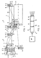
- a yarn processing system S is constituted by a yarn consuming textile machine T, like a weaving machine (as shown) or a knitting machine (not shown), by at least one feeding device F, and, if needed, by several yam processing accessory components A, altogether forming a component group G designed and structured for mutual communication for controlling and/or monitoring the co-operation during operation of the components in the component group.
- Said communication is carried out by radio transmission on a wireless basis, preferably bi-directionally, and by using a quick communication protocol with information types differing in their relative ranking. This means that the information as transmitted has differing priorities with highest priority for information intended for real-time transmission, while lower ranking information types will have to wait to be transmitted when any higher ranking information is to be transmitted simultaneously.
- Highest priority information type are trig signals, stop signals, yarn breakage signals, sync signals, necessary for the correct co-operation of the components of the component group G. Operation parameters, continuous operation signals, preparatory acceleration or deceleration commands belong to lower priority information types.
- said yarn processing system S might contain a plurality of such feeding devices F of similar or different design, each prepared for processing a yarn Y intended for the yarn consuming textile machine T.
- Feeding device F has a drive means 2 in a housing 1 supporting a yarn storage drum 2' and comprising yarn processing or monitoring components like yam sensors 3 or a yarn brake 4, e.g. at the outlet region of said feeding device F. Further not shown yarn processing accessory components could be provided at the inlet side (left-side) of feeding device F, as well.
- Said accessory components 3, 4 are connected to the power supply of the feeding device or to an own power supply and are also connected to a control and/or monitoring means C of said feeding device F.
- Said control and/or monitoring means C (an electronic control circuit having a microprocessor controlling the drive motor 2, e.g. on the basis of signals generated by components 3, 4 and independent from the yarn consumption as well as depending on information received from the textile machine T) contains a communication microprocessor B and at least one radio transmitter/receiver R (having a not shown antenna assembly).
- Said communication microprocessor B is designed for a quick communication protocol and serial or serial and digital transmission of information types differing from another in ranking such that an information type having highest priority can be transmitted in real-time and has priority over other information types having lower priority.
- Said communication microprocessor B is apt to provide said information on the basis of signals or data present in the control and/or monitoring means C for said radio transmitter/receiver R, but simultaneously is apt to derive data or signals from any information as received via its associated radio transmitter/receiver R for the components connected to said control and/or monitoring means C.
- Downstream yarn feeding device F as an accessory component A e.g. a yarn tensioner, yarn brake, or tensiometer 5 is provided having e.g. an own power supply 6 and having an own control and/or monitoring means C, again equipped with a communication microprocessor B and a radio transmitter/receiver R.
- a further accessory component A is situated, namely a yarn cutting means, a yarn selector or an auxiliary insertion conveyor 7 having an own power supply or being connected to the power supply of the textile machine, and having an own control and/or monitoring means C containing a communication microprocessor B and a radio transmitter/receiver R.
- a further component 8 e.g. a insertion means, is provided, preferably connected to the power supply of a control and/or monitoring means C of the textile machine T, equipped with communication microprocessor B and radio transmitter/receiver R.
- a further accessory component 12 is situated, e.g. an arrival sensor, having an own power supply 6 and a control and/or monitoring means C, again equipped with a communication microprocessor B and a radio transmitter/receiver R.
- Power supply for processor B or radio transmitter/receiver R could be a battery instead.
- a main control and/or monitoring means C is situated, e.g. close to the control and/or monitoring panel P of said textile machine T, to which panel P e.g. an only indicated drive means 9 of said textile machine T is connected.
- the main control and/or monitoring means C of textile machine T is equipped with at least one communication microprocessor B and an associated to, stationary radio receiver/transmitter R.
- Controller H can be used as part of the yarn processing system S.
- Controller H has an indicating and input section 13, is designed on an electronic basis and contains a communication microprocessor B and a radio transmitter/receiver R and an own power supply, preferably a battery.
- All radio transmitters/receivers R in the yam processing system S are designed for mutual wireless transmission within a frequency band as available for industrial applications.
- They are designed for ISM-standards and a frequency band of about 2.4 GHz. Instead they could be designed for a frequency band of about 400 MHz.
- the radio transmitters/receivers R as used could operate according to TDMA-standards like GSM mobile telephone systems or according to CDMA-standard, a somewhat more sophisticated form of radio transmission.
- Fig. 2 an essential part of each of the control and/or monitoring means C is shown.
- a microprocessor M P is connected to a communication microprocessor B which in tum is connected to its radio receiver/transmitter R.
- a radio media access control interface means M is situated, either in the form of hardware components or in the form of software constituted by communication microprocessor B itself or by an associated to, not shown, microprocessor.
- Radio transmitter/receiver R is equipped with an in-built antenna assembly 14. All the above-mentioned components can be mounted to a common circuit board.
- data signals received from microprocessor MP are to be transmitted by radio receiver/transmitter R, they are organised by said communication microprocessor B in order to form a computer information of one of the above-mentioned different information types of the communication protocol. Since said information types cannot be transmitted by the radio transmitter/receiver R as they are, e.g. schematic indicated interfaces 15 and 16 are used, to first organise and handle the information as built up by communication microprocessor B for radio transmitter/receiver R and to translate via second interface 16 said organised or translated information into radio signals which then are transmitted by radio receiver/transmitter R, e.g. by frequency modulation (FM).
- FM frequency modulation
- Said radio media access control interface means M is an IC (integrated circuit) not only organising and handling the respective information for the radio transmitter R, but also organising and handling any radio transmitted received information back to communication microprocessor B which is then inputting the resulting signals or data into microprocessor MP.
- Radio media access control interface means M is an administrative overhead equipment of each control and/or monitoring means C and is necessary because all participants of the wireless radio transmission via transmission paths D simultaneously can be transmitting and/or receiving and thus need an administrative organisation within the transmission system, namely said radio media access control interface means M in each of the communicating control and/or monitoring means C.
Landscapes
- Engineering & Computer Science (AREA)
- Textile Engineering (AREA)
- Physics & Mathematics (AREA)
- General Physics & Mathematics (AREA)
- Automation & Control Theory (AREA)
- Selective Calling Equipment (AREA)
- General Factory Administration (AREA)
- Spinning Or Twisting Of Yarns (AREA)
Description
- Fig. 1
- A schematic diagrammatic view of a yarn processing system, and
- Fig. 2
- A schematic view of an essential part of a control and/or monitoring means as used in the yarn processing system of Fig. 1.
Claims (8)
- Yam processing system (S), consisting of a functionally interrelated component group including at least a yam consuming textile machine (T), particularly a weaving machine or a knitting machine, and at least one yam feeding device (F), each having electric drive means (2, 9) and electronic control and/or monitoring means (C), said yam processing system further including data transmission paths (D) for mutual data transmissions between said control and/or monitoring means of components of said component group (G), said control and/or monitoring devices each having at least one communication microprocessor (B) for providing information types In the form of a communication protocol, said information types differing in ranking with real time transmission priority for at least the information type of the highest ranking over lower ranking information types, characterised in that said communication microprocessor (B) in each control and/or monitoring device (C) is connected with a stationary radio transmitter/receiver (R) for carrying out said data transmission at a single common frequency via wireless transmission paths (D) within a frequency band of about 2.4 GHz or about 400 MHz available for industrial applications and with a reach in the range of about 10 metres, and that between said communication microprocessor (B) and said radio transmitter/receiver (R) a radio media access control interface means (M) is provided.
- Yarn processing system as in claim 1, characterised in that said component group (G) includes at least one active yam processing accessory component (A) having an own electronic control and/or monitoring means (C) including a communication microprocessor (B), a radio media access control interface means (M) and a radio transmitter/receiver (R) and at least one data responsive and/or data generating element like a sensor (5) or a yam brake or yam clamp or a yam tensiometer or a yam cutter or a yam selector or a yam conveyor.
- Yam processing system as in claim 1, characterised by a radio transmitter/receiver (R) according to TDMA-standards or COMA-standards.
- Yam processing system as in claim 1, characterised in that said radio media access control interface means (M) is constituted by software in said communication microprocessor (B) or in another associated microprocessor.
- Yam processing system as in claim 1, characterised in that each information type consists of data for wireless transmission and wireless receipt by each of said radio transmitter/receivers (R), said data being configured by said communication microprocessor (B) with a frame having data containing frame fields among which at least one frame field contains general prioritising data and/or individual addressing data for at least one of said control and/or monitoring devices (C).
- Yam processing system as in claim 1, characterised in that at least one hand-held controller (H) forms part of said yam processing system (S) or a group of yam processing systems (F) and includes communication microprocessor (B), a radio media access control interface means (M) and a radio transmitter/receiver (R) for radio communication with at least one of the stationary radio transmitter/receivers (R).
- A yam processing system as in claim 1, characterised in that to set control and/or monitoring means (C) in each feeding device (F) at least one onboard data responsive and/or data generating element is connected, like a yam sensor (3, 4) or element drive means (2) or a yam tensioner or a yam brake (4) or a threading equipment or an operation parameter setting and storing element.
- Method for operating a yam processing system consisting of a yam consuming textile machine (T) like a weaving machine or a knitting machine and of a functionally associated component group (G) including at least one yam feeding device (F), each having electric drive means (2, 9) and electric control and/or monitoring means (C), said method comprising serial or serial and digital transmission of control and/or monitoring data within information of differing priorities and in the form of a communication protocol provided by communication microprocessors (B) in each of said control and/or monitoring means (C), characterised in that each information of one of the information types as provided by the communication microprocessor (B) is converted by a radio media access control interface means (M) into a radio message which is transmitted in the form of a wireless radio transmission at a single common frequency within a radio frequency band available for industrial applications of about 2.4 GHz or about 400 MHz and within a reach of about 10 metres by a radio transmitter/receiver (R) to at least another distant radio transmitter/receiver (R) and there is reconverted into a communication protocol information of said information type for the communication microprocessor of said receiving radio transmitter/receiver (R) via another radio media access control interface means (M).
Applications Claiming Priority (3)
| Application Number | Priority Date | Filing Date | Title |
|---|---|---|---|
| SE9900510A SE9900510D0 (en) | 1999-02-15 | 1999-02-15 | Yarn processing system and method to operate a yarn processing system |
| SE9900510 | 1999-02-15 | ||
| PCT/EP2000/001230 WO2000049474A1 (en) | 1999-02-15 | 2000-02-15 | Yarn processing system and method to operate a yarn processing system |
Publications (2)
| Publication Number | Publication Date |
|---|---|
| EP1153338A1 EP1153338A1 (en) | 2001-11-14 |
| EP1153338B1 true EP1153338B1 (en) | 2002-10-23 |
Family
ID=20414481
Family Applications (1)
| Application Number | Title | Priority Date | Filing Date |
|---|---|---|---|
| EP00905065A Expired - Lifetime EP1153338B1 (en) | 1999-02-15 | 2000-02-15 | Yarn processing system and method to operate a yarn processing system |
Country Status (7)
| Country | Link |
|---|---|
| US (1) | US6513554B1 (en) |
| EP (1) | EP1153338B1 (en) |
| KR (1) | KR100380905B1 (en) |
| CN (1) | CN1118731C (en) |
| DE (1) | DE60000653T2 (en) |
| SE (1) | SE9900510D0 (en) |
| WO (1) | WO2000049474A1 (en) |
Families Citing this family (22)
| Publication number | Priority date | Publication date | Assignee | Title |
|---|---|---|---|---|
| JP4054509B2 (en) * | 2000-04-19 | 2008-02-27 | 株式会社東芝 | Field device control system and computer-readable storage medium |
| SE0102323D0 (en) | 2001-06-27 | 2001-06-27 | Iropa Ag | Fadenprovendeende system und fadenliefergerät |
| DE10228516A1 (en) * | 2002-06-26 | 2004-01-15 | Iropa Ag | Method and device for configuring the control of a thread processing system |
| JP2004084111A (en) * | 2002-08-26 | 2004-03-18 | Tsudakoma Corp | Loom information display device |
| WO2004053604A1 (en) * | 2002-12-11 | 2004-06-24 | Textilma Ag | System for detecting the production data of a number of textile machines |
| ITMI20030893A1 (en) * | 2003-04-30 | 2004-11-01 | Riccardo Lonati | PERIPHERAL DEVICE NUMBERING PROCEDURE |
| JP4149367B2 (en) * | 2003-11-25 | 2008-09-10 | 津田駒工業株式会社 | Textile machine setting display device |
| JP2005275731A (en) * | 2004-03-24 | 2005-10-06 | Sharp Corp | Factory data management method and data management system |
| CN1700621B (en) * | 2004-05-20 | 2010-04-28 | 联想(北京)有限公司 | A correlation monitoring system and a monitoring correlation realization method |
| ITRN20040056A1 (en) * | 2004-11-02 | 2005-02-02 | Urbinati Srl | The transplanting machine |
| KR100652876B1 (en) * | 2005-09-26 | 2006-12-01 | 볼보 컨스트럭션 이키프먼트 홀딩 스웨덴 에이비 | Wireless electric field system of construction machine and construction machine maintenance system using the same |
| AT504670B1 (en) * | 2006-11-28 | 2008-07-15 | Keba Ag | METHOD FOR OPERATING A WIRELESS COMMUNICATION CONNECTION BETWEEN A MOBILE HAND CONTROL DEVICE AND A MACHINE CONTROL, AND CORRESPONDING SYSTEM COMPONENTS |
| JP2009242029A (en) * | 2008-03-28 | 2009-10-22 | Murata Mach Ltd | Textile machine system and textile machine |
| JP5260131B2 (en) * | 2008-04-28 | 2013-08-14 | 株式会社エヌ・ティ・ティ・ドコモ | Base station, mobile station, and common information communication method |
| CN102061537A (en) * | 2011-01-27 | 2011-05-18 | 北京经纬纺机新技术有限公司 | Wireless management system for yarn breakage detection of spinning frame and management method thereof |
| DE102014109659A1 (en) * | 2014-07-10 | 2016-01-14 | Sipra Patententwicklungs- Und Beteiligungsgesellschaft Mbh | Circular knitting machine with a machine control device |
| DE102015002922A1 (en) * | 2015-03-04 | 2016-09-08 | Oerlikon Textile Gmbh & Co. Kg | Machinery for the production or treatment of synthetic threads |
| CZ2015212A3 (en) * | 2015-03-26 | 2016-12-28 | Rieter Cz S.R.O. | Yarn producing or processing textile machine provided with wireless communication interface |
| KR101616413B1 (en) * | 2015-04-06 | 2016-04-29 | 엘림스마트 주식회사 | A WEAVING LOOM MONITORING AND MANAGEMNET SYSTEM BASED Internet Of Things Platform |
| JP6374369B2 (en) * | 2015-11-06 | 2018-08-15 | 株式会社豊田自動織機 | Weft measuring device for loom |
| CN106873556B (en) * | 2017-03-07 | 2019-10-29 | 广东顺德中山大学卡内基梅隆大学国际联合研究院 | A kind of dyeing assembly line multi-task scheduling control method |
| IT202400004420A1 (en) * | 2024-02-29 | 2025-08-29 | Roj S R L | WEFT FEEDER FOR WEAVING LOOM COMPRISING AN INDEPENDENT OPTICAL UNIT, INTEGRATED IN THE ELECTROMAGNETIC UNIT FOR RELEASING THE WEFT THREAD |
Family Cites Families (5)
| Publication number | Priority date | Publication date | Assignee | Title |
|---|---|---|---|---|
| SE8900534D0 (en) * | 1989-02-16 | 1989-02-16 | Iro Ab | DEVICE TO CONTROL AND / OR MONITOR IN FIRST HAND IN OR AT THE TEXTILE MACHINE |
| SE466726B (en) | 1990-08-20 | 1992-03-23 | Kent Lennartsson | DISTRIBUTED COMPUTER SYSTEM DEVICE |
| CA2203561C (en) | 1994-10-24 | 2004-09-21 | Thomas Andrew Boyd | Apparatus for providing access to field devices in a distributed control system |
| US6246883B1 (en) * | 1996-12-24 | 2001-06-12 | Lucent Technologies, Inc. | Mobile base station |
| US6061604A (en) | 1997-05-06 | 2000-05-09 | Gas Research Institute | RF base repeater for automated residence management system |
-
1999
- 1999-02-15 SE SE9900510A patent/SE9900510D0/en unknown
-
2000
- 2000-02-15 DE DE60000653T patent/DE60000653T2/en not_active Expired - Lifetime
- 2000-02-15 US US09/913,784 patent/US6513554B1/en not_active Expired - Fee Related
- 2000-02-15 CN CN00804984A patent/CN1118731C/en not_active Expired - Fee Related
- 2000-02-15 WO PCT/EP2000/001230 patent/WO2000049474A1/en not_active Ceased
- 2000-02-15 KR KR10-2001-7010342A patent/KR100380905B1/en not_active Expired - Fee Related
- 2000-02-15 EP EP00905065A patent/EP1153338B1/en not_active Expired - Lifetime
Also Published As
| Publication number | Publication date |
|---|---|
| EP1153338A1 (en) | 2001-11-14 |
| WO2000049474A1 (en) | 2000-08-24 |
| KR20010102151A (en) | 2001-11-15 |
| CN1118731C (en) | 2003-08-20 |
| CN1343328A (en) | 2002-04-03 |
| DE60000653D1 (en) | 2002-11-28 |
| US6513554B1 (en) | 2003-02-04 |
| KR100380905B1 (en) | 2003-04-18 |
| DE60000653T2 (en) | 2003-06-26 |
| SE9900510D0 (en) | 1999-02-15 |
Similar Documents
| Publication | Publication Date | Title |
|---|---|---|
| US6513554B1 (en) | Yarn processing system and method to operate a yarn processing system | |
| EP1698081B1 (en) | Bus powered wireless transmitter | |
| EP0458875B1 (en) | Arrangement for controlling yarn feed elements/yarn feed functions in or on a textile machine | |
| AU2012286733B2 (en) | Systems and methods for wireless communication of power distribution information | |
| CA1143826A (en) | Data communications terminal | |
| CA2223260A1 (en) | Electric power system protection and control system and distributed control system | |
| NZ196686A (en) | Remote meter reading control unit | |
| CN103428005A (en) | Interface module with power over ethernet function | |
| WO2002025307A2 (en) | Gps data logger with automatic wireless download | |
| US6091527A (en) | Communications device having an optical bus, and a method for controlling its operation | |
| US5631931A (en) | Bus type clock supplying system for providing a clock in a communication system with a plurality of clock bus lines | |
| CN100390690C (en) | System for controlling several textile machines and determining their product data | |
| US8032261B1 (en) | Cooling system with adaptive protocol cooling unit | |
| WO1997013186A1 (en) | Device for the operation of appliances, utilities and services within a building | |
| US20070139209A1 (en) | Intelligent duct smoke detector | |
| EP1224514B1 (en) | Yarn processing system | |
| US20020060627A1 (en) | Sensor unit | |
| US4803411A (en) | Industrial sewing machine | |
| CN216411938U (en) | System for reliably transmitting vibration temperature data and wirelessly accessing DCS | |
| KR100347323B1 (en) | Apparatus for collecting alarm information of cdma system using token ring method | |
| JPS6152057A (en) | Wide range centralized supervisoty system | |
| KR100241915B1 (en) | Self-protection apparatus and method for order wire signal in transmission network of optical transmission system | |
| JPH07152952A (en) | Automatic vending machine and its data gathering system | |
| JPH0683507B2 (en) | Supervisory control method | |
| HK1083649B (en) | A system for determining the production data of and controlling a number of textile machines |
Legal Events
| Date | Code | Title | Description |
|---|---|---|---|
| PUAI | Public reference made under article 153(3) epc to a published international application that has entered the european phase |
Free format text: ORIGINAL CODE: 0009012 |
|
| 17P | Request for examination filed |
Effective date: 20010809 |
|
| AK | Designated contracting states |
Kind code of ref document: A1 Designated state(s): AT BE CH CY DE DK ES FI FR GB GR IE IT LI LU MC NL PT SE |
|
| RAP1 | Party data changed (applicant data changed or rights of an application transferred) |
Owner name: IROPA AG |
|
| GRAG | Despatch of communication of intention to grant |
Free format text: ORIGINAL CODE: EPIDOS AGRA |
|
| RAP1 | Party data changed (applicant data changed or rights of an application transferred) |
Owner name: IROPA AG |
|
| 17Q | First examination report despatched |
Effective date: 20011218 |
|
| GRAG | Despatch of communication of intention to grant |
Free format text: ORIGINAL CODE: EPIDOS AGRA |
|
| GRAH | Despatch of communication of intention to grant a patent |
Free format text: ORIGINAL CODE: EPIDOS IGRA |
|
| GRAH | Despatch of communication of intention to grant a patent |
Free format text: ORIGINAL CODE: EPIDOS IGRA |
|
| GRAA | (expected) grant |
Free format text: ORIGINAL CODE: 0009210 |
|
| AK | Designated contracting states |
Kind code of ref document: B1 Designated state(s): BE CH DE IT LI NL |
|
| REG | Reference to a national code |
Ref country code: CH Ref legal event code: EP |
|
| REG | Reference to a national code |
Ref country code: IE Ref legal event code: FG4D |
|
| REF | Corresponds to: |
Ref document number: 60000653 Country of ref document: DE Date of ref document: 20021128 |
|
| REG | Reference to a national code |
Ref country code: CH Ref legal event code: NV Representative=s name: BOVARD AG PATENTANWAELTE |
|
| PLBE | No opposition filed within time limit |
Free format text: ORIGINAL CODE: 0009261 |
|
| STAA | Information on the status of an ep patent application or granted ep patent |
Free format text: STATUS: NO OPPOSITION FILED WITHIN TIME LIMIT |
|
| 26N | No opposition filed |
Effective date: 20030724 |
|
| REG | Reference to a national code |
Ref country code: IE Ref legal event code: MM4A |
|
| PGFP | Annual fee paid to national office [announced via postgrant information from national office to epo] |
Ref country code: NL Payment date: 20050222 Year of fee payment: 6 |
|
| PG25 | Lapsed in a contracting state [announced via postgrant information from national office to epo] |
Ref country code: NL Free format text: LAPSE BECAUSE OF NON-PAYMENT OF DUE FEES Effective date: 20060901 |
|
| NLV4 | Nl: lapsed or anulled due to non-payment of the annual fee |
Effective date: 20060901 |
|
| PGFP | Annual fee paid to national office [announced via postgrant information from national office to epo] |
Ref country code: CH Payment date: 20090226 Year of fee payment: 10 |
|
| REG | Reference to a national code |
Ref country code: CH Ref legal event code: PL |
|
| PG25 | Lapsed in a contracting state [announced via postgrant information from national office to epo] |
Ref country code: CH Free format text: LAPSE BECAUSE OF NON-PAYMENT OF DUE FEES Effective date: 20100228 Ref country code: LI Free format text: LAPSE BECAUSE OF NON-PAYMENT OF DUE FEES Effective date: 20100228 |
|
| PGFP | Annual fee paid to national office [announced via postgrant information from national office to epo] |
Ref country code: DE Payment date: 20150216 Year of fee payment: 16 Ref country code: IT Payment date: 20150223 Year of fee payment: 16 |
|
| PGFP | Annual fee paid to national office [announced via postgrant information from national office to epo] |
Ref country code: BE Payment date: 20150216 Year of fee payment: 16 |
|
| PG25 | Lapsed in a contracting state [announced via postgrant information from national office to epo] |
Ref country code: BE Free format text: LAPSE BECAUSE OF NON-PAYMENT OF DUE FEES Effective date: 20160229 |
|
| REG | Reference to a national code |
Ref country code: DE Ref legal event code: R119 Ref document number: 60000653 Country of ref document: DE |
|
| PG25 | Lapsed in a contracting state [announced via postgrant information from national office to epo] |
Ref country code: IT Free format text: LAPSE BECAUSE OF NON-PAYMENT OF DUE FEES Effective date: 20160215 |
|
| PG25 | Lapsed in a contracting state [announced via postgrant information from national office to epo] |
Ref country code: DE Free format text: LAPSE BECAUSE OF NON-PAYMENT OF DUE FEES Effective date: 20160901 |