EP1152485B1 - Radio communication device - Google Patents
Radio communication device Download PDFInfo
- Publication number
- EP1152485B1 EP1152485B1 EP00902973.7A EP00902973A EP1152485B1 EP 1152485 B1 EP1152485 B1 EP 1152485B1 EP 00902973 A EP00902973 A EP 00902973A EP 1152485 B1 EP1152485 B1 EP 1152485B1
- Authority
- EP
- European Patent Office
- Prior art keywords
- electromagnetic wave
- dielectric body
- antenna
- communication device
- radio communication
- Prior art date
- Legal status (The legal status is an assumption and is not a legal conclusion. Google has not performed a legal analysis and makes no representation as to the accuracy of the status listed.)
- Expired - Lifetime
Links
Images


Classifications
-
- H—ELECTRICITY
- H01—ELECTRIC ELEMENTS
- H01Q—ANTENNAS, i.e. RADIO AERIALS
- H01Q23/00—Antennas with active circuits or circuit elements integrated within them or attached to them
-
- H—ELECTRICITY
- H01—ELECTRIC ELEMENTS
- H01Q—ANTENNAS, i.e. RADIO AERIALS
- H01Q1/00—Details of, or arrangements associated with, antennas
- H01Q1/42—Housings not intimately mechanically associated with radiating elements, e.g. radome
-
- H—ELECTRICITY
- H01—ELECTRIC ELEMENTS
- H01Q—ANTENNAS, i.e. RADIO AERIALS
- H01Q13/00—Waveguide horns or mouths; Slot antennas; Leaky-waveguide antennas; Equivalent structures causing radiation along the transmission path of a guided wave
- H01Q13/10—Resonant slot antennas
-
- H—ELECTRICITY
- H01—ELECTRIC ELEMENTS
- H01Q—ANTENNAS, i.e. RADIO AERIALS
- H01Q19/00—Combinations of primary active antenna elements and units with secondary devices, e.g. with quasi-optical devices, for giving the antenna a desired directional characteristic
- H01Q19/06—Combinations of primary active antenna elements and units with secondary devices, e.g. with quasi-optical devices, for giving the antenna a desired directional characteristic using refracting or diffracting devices, e.g. lens
- H01Q19/062—Combinations of primary active antenna elements and units with secondary devices, e.g. with quasi-optical devices, for giving the antenna a desired directional characteristic using refracting or diffracting devices, e.g. lens for focusing
-
- H—ELECTRICITY
- H01—ELECTRIC ELEMENTS
- H01L—SEMICONDUCTOR DEVICES NOT COVERED BY CLASS H10
- H01L2223/00—Details relating to semiconductor or other solid state devices covered by the group H01L23/00
- H01L2223/58—Structural electrical arrangements for semiconductor devices not otherwise provided for
- H01L2223/64—Impedance arrangements
- H01L2223/66—High-frequency adaptations
- H01L2223/6605—High-frequency electrical connections
- H01L2223/6627—Waveguides, e.g. microstrip line, strip line, coplanar line
-
- H—ELECTRICITY
- H01—ELECTRIC ELEMENTS
- H01L—SEMICONDUCTOR DEVICES NOT COVERED BY CLASS H10
- H01L2224/00—Indexing scheme for arrangements for connecting or disconnecting semiconductor or solid-state bodies and methods related thereto as covered by H01L24/00
- H01L2224/01—Means for bonding being attached to, or being formed on, the surface to be connected, e.g. chip-to-package, die-attach, "first-level" interconnects; Manufacturing methods related thereto
- H01L2224/10—Bump connectors; Manufacturing methods related thereto
- H01L2224/15—Structure, shape, material or disposition of the bump connectors after the connecting process
- H01L2224/16—Structure, shape, material or disposition of the bump connectors after the connecting process of an individual bump connector
- H01L2224/161—Disposition
- H01L2224/16151—Disposition the bump connector connecting between a semiconductor or solid-state body and an item not being a semiconductor or solid-state body, e.g. chip-to-substrate, chip-to-passive
- H01L2224/16221—Disposition the bump connector connecting between a semiconductor or solid-state body and an item not being a semiconductor or solid-state body, e.g. chip-to-substrate, chip-to-passive the body and the item being stacked
- H01L2224/16225—Disposition the bump connector connecting between a semiconductor or solid-state body and an item not being a semiconductor or solid-state body, e.g. chip-to-substrate, chip-to-passive the body and the item being stacked the item being non-metallic, e.g. insulating substrate with or without metallisation
-
- H—ELECTRICITY
- H01—ELECTRIC ELEMENTS
- H01L—SEMICONDUCTOR DEVICES NOT COVERED BY CLASS H10
- H01L2924/00—Indexing scheme for arrangements or methods for connecting or disconnecting semiconductor or solid-state bodies as covered by H01L24/00
- H01L2924/19—Details of hybrid assemblies other than the semiconductor or other solid state devices to be connected
- H01L2924/1901—Structure
- H01L2924/1903—Structure including wave guides
Definitions
- the present invention relates to radio communication devices for pseudo-millimetric and millimetric wavebands.
- a radio communication device in a frequency region below the microwave band, a radio communication device has been used by independently designing and manufacturing a high-frequency unit formed of a frequency converter circuit, a local oscillator circuit, an amplifier circuit and so on and an antenna and connecting them by means of a connector or mounting them on an identical substrate.
- a radio communication device in the pseudo-millimetric and millimetric waveband regions of higher frequencies, losses in a power supply line and connecting portions between the high-frequency unit and the antenna rapidly increase, and this has been a serious problem in providing a practicable efficient device.
- the antenna and the high-frequency unit are integrated with each other for the frequencies higher than the pseudo-millimetric and millimetric wavebands.
- the antenna element and the antenna have the same meaning.
- Japanese Patent Laid-Open Publication No. HEI 10-79623 discloses one example of a radio communication device in which an antenna and a high-frequency unit are housed in an identical package.
- a substrate on the identical surface of which the antenna element and the high-frequency unit are formed and a package conductor for hermetically sealing the antenna element and the high-frequency unit formed on the substrate in a common space are provided, and a partial region that belongs to the package conductor and faces the antenna element is nonconductive.
- a conductive shield plate for preventing electromagnetic mutual interferences is provided between a high-frequency unit and an antenna element.
- NRD nonradiative dielectric
- a dielectric resonator a dielectric lens
- Radiation is made in the vertical direction from the NRD circuit surface by converting the LSM01 mode that is the propagation mode of the NRD guide into the HE11 mode of the dielectric resonator and further making excitation of a slot on the resonator, and a beam is formed by means of the dielectric lens.
- the losses between the high-frequency unit and the antenna can be restrained.
- the system that employs the NRD guide is often used in the communication system for the millimetric waveband.
- a multislot antenna and a frequency converter unit are integrated with each other is disclosed in C-2-52 of General Meeting in 1998 of The Institute of Electronics, Information and Communication Engineers.
- a multislot antenna and a coplanar transmission line connected to the multislot antenna are formed in a pattern on a dielectric substrate, and a frequency converter circuit is formed at the other terminal of the coplanar transmission line.
- An RF signal received by the multislot antenna passes through the coplanar transmission line so as to be inputted to the frequency converter circuit, while a local oscillation signal is inputted from an LO terminal.
- the RF signal is mixed with the local oscillation signal in the frequency converter circuit so as to be frequency converted and outputted as an IF signal from an IF terminal.
- the multislot antenna is suitable for millimetric waveband communications characteristic of a wide band property for the reasons that matching can easily be achieved by adjusting the number of slots and that a wide bandwidth can be provided in comparison with the patch antenna and the like.
- the radio communication device for the frequency region below the microwave band has conventionally been used by independently designing and manufacturing a high-frequency unit formed of a frequency converter circuit, a local oscillator circuit, an amplifier circuit and so on and an antenna and connecting them by means of a connector or mounting them on an identical substrate.
- DE 43 15 847 A1 describes a transmitter/receiver unit for millimetre wave signals, wherein integrated circuits are arranged on one substrate side and an antenna element is provided on the opposing substrate side.
- a dielectric lens concentrates the antenna radiation.
- EP 0 281 042 A2 refers to a multi-spectral antenna with the thickness of a transparent reflector element adjusted to the wavelength of a millimetre wave signal.
- US 2,761,141 describes continuously varying dielectric constant electromagnetic lenses.
- FR 2 760 902 describes to adjust the thickness of a flat dielectric and its distance to an electromagnetic wave radiating structure.
- this receiver unit in which an antenna and a high-frequency detection element are integrated with each other, is constructed of a high-resistance silicon lens 90, a polyethylene matching cap 91, a silicon substrate 92, and a receiver 94 formed on a gallium arsenide substrate 93.
- both the diameter of the lens and the distance between the lens and the light-concentrating surface need ten or more wavelengths, and therefore, the diameter of an extended hemisphere lens amounts to about eleven wavelengths of the wavelengths in the air in the example of the aforementioned technical report. Furthermore, a distance from the center of the hemisphere to the substrate is extended with the lens material, providing an antenna with a basically three-dimensional structure.
- a parabola antenna with a reflecting mirror which is generalized in the radio astronomy, the satellite communication terrestrial station and the like, similarly becomes a device of a three-dimensional mechanical structure and is not regarded as a technology to be widely popularized in the future.
- An antenna device technology of a quite new concept has been strongly demanded in order to provide a high-performance low-cost millimetric wave radio communication device.
- the NRD guide itself has excellent low-loss transmission path characteristic, whereas its has drawbacks in the structure as a three-dimensional circuit in addition to a limitation in device miniaturization and poor mass productivity.
- the multislot antenna and the frequency converter circuit are not electromagnetically separated and disadvantageously interfere with each other, and no concrete measure for securing a stable operation is taken.
- the present invention provides radio communication devices according to the independent claims.
- a radio communication device for a pseudo-millimetric or millimetric waveband
- an antenna section of the radio communication device is comprised of an electromagnetic wave radiation structure connected to a transmitter-receiver circuit section or a transmitter circuit section or a receiver circuit section and a dielectric body
- the dielectric body is arranged adjacent to the electromagnetic wave radiation structure and has a structure that is thick in a center region and thin in a peripheral portion, and a thickness of the center region of the dielectric body is approximately (1/2) ⁇ m (m: integer) of an effective wavelength of a desired electromagnetic wave in the dielectric body.
- the reflected wave of the electromagnetic wave entering the dielectric body is weakened and concurrently a transmitted wave is strengthened.
- the wave is re-radiated (or received by being coupled with an electromagnetic wave radiation structure) as an electromagnetic wave source of an expanded effective opening, and the antenna gain is increased.
- a radio communication device for a pseudo-millimetric or millimetric waveband
- an antenna section of the radio communication device is comprised of an electromagnetic wave radiation structure connected to a transmitter-receiver circuit section or a transmitter circuit section or a receiver circuit section and a dielectric body
- the dielectric body is arranged adjacent to the electromagnetic wave radiation structure and is a parallel-flat-plate-shaped convergence medium that has a high permittivity in a center region and a low permittivity in a peripheral region, and a thickness of the center region of the dielectric body is approximately (1/2) ⁇ m (m: integer) of an effective wavelength of a desired electromagnetic wave in the dielectric body.
- the reflected wave of the electromagnetic wave entering the dielectric body is weakened and concurrently a transmitted wave is strengthened.
- the wave is re-radiated (or received by being coupled with an electromagnetic wave radiation structure) as an electromagnetic wave source of an expanded effective opening, and the antenna gain is increased.
- m of approximately (1/2) ⁇ m is not greater than four.
- the electromagnetic wave can be stored more efficiently in the dielectric body, and the antenna gain can be increased.
- a diameter of the dielectric body at an opening toward a space is set within a range of about one to six times the wavelength of the desired electromagnetic wave in the air.
- the electromagnetic wave can be stored much more efficiently in the dielectric body, and the antenna gain can be increased.
- a plurality of electromagnetic wave radiation structures joined to an electromagnetic waveguide connected to the transmitter-receiver or the transmitter circuit section or the receiver circuit section are arranged on an identical surface, and the diameter of the dielectric body at an opening toward the space is within a range of four to twenty times the wavelength of the desired electromagnetic wave in the air.
- a distance between the dielectric body and the electromagnetic wave radiation structure is approximately (1/2) ⁇ n (n: integer) of the wavelength of the desired electromagnetic wave in the air.
- the electromagnetic wave can be stored more efficiently in the dielectric body, and the antenna gain can be increased.
- n of (1/2) ⁇ n of the wavelength is not greater than four.
- the electromagnetic wave can be stored more efficiently in the dielectric body, and the antenna gain can be increased.
- the electromagnetic wave radiation structure is any one of a slot antenna structure, a multislot antenna structure, a conductor patch structure, a planar spiral antenna structure and a bowtie antenna structure.
- the electromagnetic waveguide is any one of a microstrip transmission line, a coplanar type transmission line (CPW), a coplanar type transmission line (GCPW) backed with a conductive sheet, a slot type waveguide, an image waveguide, a nonradiative dielectric line, a coaxial line and a metallic waveguide.
- CPW coplanar type transmission line
- GCPW coplanar type transmission line
- Fig. 1A is a sectional view of a radio communication device according to a first example.
- An MMIC 104 that constitutes a high-frequency unit is flip-chip connected onto a dielectric base 103 on which a multislot antenna 101 and a coplanar transmission line 102 are formed in a pattern.
- An upper surface of the base 103 on which the MMIC 104, the multislot antenna 101 and the coplanar transmission line 102 are formed in a pattern is hermetically sealed by a conductor package 105 that concurrently serves as an electromagnetic wave reflector.
- a distance D1 between the dielectric base 103 and the conductor package 105 is one-fourth of the wavelength of the desired electromagnetic wave.
- a lower portion of the base 103 is covered with a conductive sheet 107 that has an electromagnetic wave passage opening 106.
- This conductive sheet 107 plays the role of a shield, but the sheet is not required to hermetically seal inside.
- the reference numeral 108 denotes an intermediate frequency (IF) signal processing unit.
- Fig. 1B shows a block diagram of one structural example of the MMIC 104 that operates as a high-frequency unit.
- This MMIC 104 is constructed of an intermediate frequency (IF) signal amplifier 109, a frequency converter 110, a radio frequency (RF) signal amplifier 111 and a local signal generating unit 112.
- IF intermediate frequency
- RF radio frequency
- Fig. 1B shows the example in which these functions are integrated into one chip, the functions can also be distributed into several chips.
- An IF signal 113 generated by the IF signal processing unit 108 is inputted to the MMIC 104, amplified by the IF signal amplifier 109 in the MMIC 104, mixed with a local signal from the local signal generator 112 in the frequency converter 110, converted into an RF signal and amplified by the RF signal amplifier 111.
- An RF signal 114 outputted from the MMIC 104 is inputted to the multislot antenna 101 and radiated upwardly and downwardly.
- the upwardly radiated electromagnetic wave 118 is reflected on the conductor package 105, superimposed on an output radiation electromagnetic wave 119 radiated from a lower portion of the base 103 and then radiated.
- the conductor package 105 located in the upper portion of the dielectric base 103 that concurrently serves as the reflector is not required to be specifically devised, and the conventional hermetic sealing technology for microwave element and the conventional package material can be used without modification.
- the conductive sheet 107 located under the dielectric base 103 plays the role of a shield for electromagnetic waves, but the sheet is not required to hermetically seal inside.
- the transmitter that converts the IF signal 113 into the RF signal 114 and radiates the signal is described here, it is allowed to constitute a receiver that receives an RF signal and converts the signal into an IF signal by modifying the structure of the MMIC without modifying any structure of the other portions.
- Fig. 1C shows a plan view of the dielectric base on which the multislot antenna 101 and the coplanar transmission line shown in Fig. 1A are formed in a pattern.
- the reference numerals 115 and 116 denote wiring lines for applying a direct current (DC) bias to the MMIC 104, while 117 denotes an IF input terminal.
- DC direct current
- the high-frequency unit 104, the antenna 101 and the coplanar transmission line 102, which are arranged on the dielectric base 103, are hermetically sealed by a package 105 having no passage opening for electromagnetic wave and the dielectric base 103.
- the electromagnetic wave is taken out of the electromagnetic wave passage opening 106 provided for the conductive sheet 107 attached to the opposite side of the base 103 through the dielectric base 103.
- Fig. 2 is a sectional view of a radio communication device according to a second example.
- the different point from the first example is only that a convex lens 201 is provided outside the passage opening 106 for electromagnetic wave, and the other constructions are same as those of the first example.
- An electromagnetic wave 119 radiated by the same operational principle as in the first example is refracted and converged by the convex lens 201, and therefore, the antenna gain is increased.
- the diameter of this convex lens 201 is set about five times the effective wavelength of the desired wave. Moreover, by optimizing the radius of curvature of the convex lens 201, the desired antenna gain can be obtained.
- This convex lens 201 is manufactured by mechanically cutting or forming by means of a metallic mold the material of polymethyl methacrylate, styrene acrylonitrile, polycarbonate, polystyrene, epoxy, polymethylpentene, polytetrafluoroethylene, polyethylene, Teflon or the like besides quartz and glass.
- Fig. 2 shows a plano-convex lens as a lens that has an effect of convergence, the lens can also be replaced by a double-convex lens.
- the convex lens 201 is employed here as an equivalent of the convex-lens-shaped dielectric body. Moreover, the diameter of the convex lens 201 is set about five times the effective wavelength of the desired wave. About five times the effective wavelength becomes about one wavelength to four wavelengths in terms of the wavelength in the air, depending on the permittivity of the convex lens.
- the multislot antenna 101 is employed as the electromagnetic wave radiation structure
- the coplanar line 102 is employed as an electromagnetic waveguide.
- these members are not limited to the above-mentioned ones, and the effect of the arrangement that the dielectric body and the electromagnetic wave radiation structure are placed adjacent to each other does not change even if other structures are employed.
- Fig. 3 is a sectional view of a radio communication device according to a third example.
- This third example differs from the second example only in that the convex lens 201 is separated from the passage opening 106 for electromagnetic wave. That is, by interposing a spacer 207 between the convex lens 201 and the conductive sheet 107, the desired antenna gain can be obtained by adjusting the distance between the multislot antenna 101 and the center of the lens for optimization, although the distance is within the focal distance of the lens.
- Fig. 4 is a sectional view of a radio communication device according to a fourth example.
- This fourth example differs from the second example in that a lens 203 obtained by zoning the plano-convex lens 201 is used.
- this zoned lens 203 the volume of the lens can be reduced without impairing the effect of refraction of the electromagnetic wave, and this allows the radio communication device to have a small size and a light weight.
- Fig. 5A is a sectional view of a radio communication device according to a fifth example.
- This fifth example differs from the second example in that shield plates 501a and 501b are placed on both sides of the multislot antenna 101 between the dielectric base 103 and the package 105.
- Fig. 5B shows its plan view.
- Fig. 5C shows a cross section (A-A') of Fig. 5B .
- a cut 502 is formed on the shield plate 501a above the coplanar transmission line 102 that connects the MMIC 104 with the multislot antenna 101.
- the unnecessary waveguide mode can be cut off, and this enables the removal of mutual influence exerted between the multislot antenna 101 and the high-frequency unit 104.
- a distance c from the shield plate 501a and the shield plate 501b to the center of the multislot antenna 101 is set to one-fourth of the wavelength of the desired electromagnetic wave, the unnecessary reflection is cancelled and the antenna efficiency is maximized.
- the distance of communications can be increased and the signal transmission error can be reduced, enabling the practical use of the pseudo-millimetric wave and millimetric wave transmission.
- Fig. 5F is a view of a cross section (B-B') of Fig. 5B .
- Fig. 6 is a sectional view of a radio communication device according to a sixth example.
- This sixth example differs from the second example only in that the convex lens 201 and the dielectric base 103 are connected with each other by means of a dielectric waveguide section 601.
- an electromagnetic wave radiated from the multislot antenna 101 is guided to the convex lens 201 by the dielectric waveguide section 601. Moreover, since no air layer exists between the convex lens 201 and the multislot antenna 101 due to the dielectric waveguide section 601, and therefore, the unnecessary reflection on the convex lens 201 and the multislot antenna 101 can be restrained.
- the dielectric waveguide section 601 is manufactured by mechanically cutting or forming by means of a metallic mold the material of polymethyl methacrylate, styrene acrylonitrile, polycarbonate, polystyrene, epoxy, polymethylpentene, polytetrafluoroethylene, polyethylene, Teflon or the like besides quartz and glass.
- a metallic mold the material of polymethyl methacrylate, styrene acrylonitrile, polycarbonate, polystyrene, epoxy, polymethylpentene, polytetrafluoroethylene, polyethylene, Teflon or the like besides quartz and glass.
- the materials of the convex lens 201 and the dielectric waveguide section 601 are not necessarily be the same. However, it is also desirable that their permittivities are close to each other. It is also possible to manufacture the convex lens 201 and the dielectric waveguide section 601 by concurrently molding them with an identical material by means of a metallic mold.
- Fig. 7 is a sectional view of a radio communication device according to a seventh example.
- This seventh example differs from the sixth example in that a dielectric waveguide section 701 is placed between the upper surface of the dielectric base 103 and the package 105 and that the distance between the upper portion of the dielectric base 103 and the upper portion of the package 105 is set to one-fourth of the effective wavelength of the electric wave in the dielectric waveguide section 701.
- the beam width of the electromagnetic wave radiated upwardly of the multislot antenna 101 is narrowed by the dielectric waveguide section 701 and reflected, and an electric wave 702 is further radiated into the space via the dielectric waveguide section 701 and the convex lens 201.
- the dielectric waveguide section 701 operates as a guide of the radiated wave from the multislot antenna 101, also producing the effect of preventing the unnecessary transmission of electromagnetic waves in the package.
- this dielectric waveguide section 701 is manufactured by mechanically cutting or forming by means of a metallic mold the material of polymethyl methacrylate, styrene acrylonitrile, polycarbonate, polystyrene, epoxy, polymethylpentene, polytetrafluoroethylene, polyethylene, Teflon or the like besides quartz and glass.
- Fig. 8A is a sectional view of a radio communication device according to a eighth example.
- This eighth example differs from the second example only in that a reflecting mirror 801 having an converging effect is provided inside the conductor package 105 above the dielectric base 103.
- the provided reflecting mirror 801 that has the converging effect plays the role of reflecting an electromagnetic wave 802 radiated upwardly of the multislot antenna 101 as a reflected wave 803 by narrowing the width of the radiated wave toward the multislot antenna side and preventing the electromagnetic wave from being transmitted in unnecessary directions inside the conductor package 105, as compared with the case where the reflecting mirror 801 having the converging effect is not provided.
- the reflecting mirror 801 having the converging effect is formed of a material of aluminum, gold, copper or the like. It is also acceptable to concurrently manufacture the reflecting mirror 801 having the converging effect and the conductor package 105.
- Fig. 8B shows another example of the reflecting mirror that has the converging effect, provided by a package 804 having a concave mirror 804a which is partially made concave.
- Fig. 8C shows another example of the reflecting mirror having an equivalent converging effect, provided by a convex dielectric body 805.
- Fig. 8D shows an example in which a function equal to that of the convex dielectric body 805 in Fig. 8C is equivalently provided by a plurality of circular dielectric plates 806 of different diameters, and this example has the same effect as that of the example described with reference to Fig. 8A. to Fig. 8A .
- Fig. 9 is a sectional view of a radio communication device according to a ninth example.
- This ninth example differs from the eighth example only in that a plano-convex lens 201 and the dielectric base 103 are connected by means of a dielectric waveguide section 601.
- the role of the dielectric waveguide section 601 is the same as that described in connection with the sixth example, and therefore, no description is repeated here.
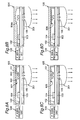
- Fig. 10 is a sectional view of a radio communication device according to the first embodiment of the present invention.
- This first embodiment is constructed of a dielectric body 1, an electromagnetic wave radiation structure 2, an electromagnetic waveguide 3, a high-frequency unit 4 and a dielectric base 7.
- the high-frequency unit 4 is a generic high-frequency unit constructed of an amplifier, a frequency converter unit, a filter and so on.
- the dielectric body 1 has a shape that is thick at the center and thin in the peripheral portion and is arranged adjacent to the electromagnetic wave radiation structure 2 while being separated apart by a distance L. Moreover, a thickness t of a center portion 1a of the dielectric body 1 was set to about 0.5 wavelength of the wavelength of the specified electromagnetic wave in the dielectric body 1. It is to be noted that the thickness t of this center portion 1a may be set to any one of about 1.0 wavelength, about 1.5 wavelengths and about two wavelengths of the wavelength of the specified electromagnetic wave in the dielectric body 1.
- An electromagnetic waveguide 3 is connected to the high-frequency unit 4, and this electromagnetic waveguide 3 is connected to the electromagnetic wave radiation structure 2.
- the dielectric body 1 is arranged opposite to this electromagnetic wave radiation structure 2.
- This dielectric body 1 has a flat bottom surface 6 that faces the electromagnetic wave radiation structure 2 and has a convex surface 5 that faces the space. With regard to this dielectric body 1, its bottom surface 6 is located apart by a distance L from the electromagnetic wave radiation structure 2, as described above.
- the electromagnetic wave radiated from the electromagnetic wave radiation structure 2 is partially reflected on the convex surface 5 and the bottom surface 6 of the dielectric body 1 and travels toward the electromagnetic wave radiation structure 2.
- a component incident on the dielectric body 1 arranged adjacently out of the electromagnetic waves radiated from the electromagnetic wave radiation structure 2 is repetitively reflected on the bottom surface 6 and the convex surface 5 of the dielectric body 1 and resonates since the thickness of the dielectric body 1 is the integral multiple of approximately 0.5 wavelength, as a consequence of which the transmitted wave of the electromagnetic wave incident on the dielectric body 1 is intensified and the reflected wave is weakened in contrast to this.
- the distribution of the electromagnetic field expands inside the dielectric body 1 by the repetitive reflection in the dielectric body 1, and this operates as an antenna having an expanded actual opening, results in increasing the antenna gain.
- the diameter D of the convex surface 5 of the dielectric body 1 serving as an opening toward the space is set within a range of about one to six times the wavelength of the desired electromagnetic wave in terms of the wavelength in the air, the greater part of the electromagnetic wave energy radiated from the electromagnetic wave radiation structure 2 is efficiently taken into the dielectric body 1.
- the electromagnetic wave energy accumulated in this dielectric body 1 is radiated as a re-radiated wave from the dielectric body 1 into the space, and therefore, the antenna gain is increased.
- the electromagnetic wave resonates between the bottom surface 6 and the electromagnetic wave radiation structure 2 and is more efficiently taken into the dielectric body 1. Therefore, the antenna gain can be increased.
- the antenna gain was measured with a plano-convex-shaped dielectric body 1 of a relative permittivity of 3.8 arranged adjacent to the multislot 2 that was a sort of the electromagnetic wave radiation structure.
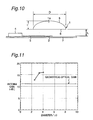
- Fig. 11 shows the measurement result of this antenna gain.
- the vertical axis represents the antenna gain (dBi)
- the horizontal axis represents the multiple of the diameter D of the convex surface 5 of the dielectric body 1 serving as the opening toward the space devided by a wavelength ⁇ 0 of the electromagnetic wave of 25 GHz in the air.
- the thickness t of the center portion 1a of the dielectric body 1 is selected so as to become about two wavelengths in terms of effective wavelength in the dielectric body 1, so that the transmissivity is maximized with the reflection on the dielectric body 1 restrained.
- the antenna gain obtained by calculation with the formula of the geometrical-optical lens under assumption that the dielectric body 1 is a virtual geometrical-optical lens expediently is indicated for comparison by the solid line.
- the diameter D of the dielectric body 1 through this measurement is 2.5 wavelengths to four wavelengths in terms of wavelength in the air, and the value is much smaller than the dimensional condition of ten wavelengths or more on the precondition of the geometrical-optical design.
- a distance L between the electromagnetic wave radiation structure (multislot) 2 and the dielectric body 1 is about the wavelength in the air, and this means a very adjacent arrangement, significantly apart from the geometrical-optical condition.
- the electromagnetic wave energy from the electromagnetic wave radiation structure 2 expanded in the dielectric body 1 and a gain higher than the antenna gain obtained substantially by the geometrical-optical design was obtained, producing a great effect in increasing the antenna gain.
- the diameter D of the dielectric body 1 is selected to 2.5 wavelengths to four wavelengths with respect to the wavelength of the specified electromagnetic wave in the air.
- a similar antenna gain increasing effect is also produced when the diameter D of the dielectric body 1 is selected to about one to six wavelengths of the aforementioned wavelength.
- Fig. 12 shows a relation of the distance L between the dielectric body 1 and the electromagnetic wave radiation structure 2 to the antenna gain when the diameter D of the convex surface 5 of the dielectric body 1 serving as the opening toward the space is set 2.5 times the wavelength of the desired electromagnetic wave in the air.
- the antenna gain exhibits a peak when this distance L is 0.5 wavelength and one wavelength with respect to the wavelength ⁇ 0 in the air. Also, this measurement result is significantly different from the result presumed by the geometrical-optical design.
- the antenna gain was increased when the distance L was set to the wavelength ⁇ 0 /2 or the wavelength ⁇ 0 because the desired electromagnetic wave was more efficiently taken into the dielectric body 1 by the resonance between the dielectric body 1 and the electromagnetic wave radiation structure 2, according to these measurement results.
- a substantially similar effect increasing the antenna gain is produced when the distance L between the dielectric body 1 and the electromagnetic wave radiation structure 2 is set to about 1.5 wavelength (1.5 ⁇ 0 ) or two wavelengths (2 ⁇ 0 ).
- the aforementioned experimental results indicate that the present invention is obviously different from the operation of the conventional geometrical-optical lens.
- the increase in gain by virtue of the combination with the dielectric body corresponds to the diameter D of the lens-shaped dielectric body 1.
- This can be understood for the reasons that the greater part of the electromagnetic wave energy radiated from the electromagnetic wave radiation structure 2 is taken into the dielectric body 1 by the proximity effect of the dielectric body 1 arranged adjacent to the electromagnetic wave radiation structure 2 located apart by the distance L and further the effective high gain is achieved by re-radiation with the minute-size plano-convex-shaped dielectric body 1 used as a wave source.
- the experimental results indicate that the reflected waves between the surface 6 of the dielectric body 1 and the electromagnetic wave radiation structure 2 are effectively combined again and efficiently radiated into the space when the interval L is close to the integral multiple of the one-half wavelength.
- the operations of the dielectric body 1 and the electromagnetic wave radiation structure 2 produce the reversible effect for the achievement of the same antenna gain in a receiver.
- a receiver can also be constructed.
- the dielectric body 1 is not limited to the plano-convex-shape and, as shown in Fig. 13A , a dielectric body 41 whose surface on the radiation space side is constructed of a flat surface and a peripheral curved surface may be provided. Furthermore, a trapezoidal dielectric body 42 may be provided as shown in Fig. 13B , or a dielectric body 43 of a structure in which a plurality of disks whose diameters are reduced in order are stacked may be provided as shown in Fig. 13C .
- a slot antenna structure 51 having a slot 51a may be provided as shown in Fig. 14A
- a multislot antenna structure 52 in which a plurality of strip segments 52b are arranged in an opening section 52a may be provided as shown in Fig. 14B
- a conductor patch structure 53 may be provided as shown in Fig. 14C
- a bowtie antenna structure 54 may be provided as shown in Fig. 14D .
- a planar spiral or a waveguide slot having a flange structure or the like can be employed.
- the periphery of an identical surface of the conductor patch structure shown in Fig. 14C as an example of the electromagnetic wave radiation structure 2 may be a conductor surface separated from the central side by a gap without conductor.
- the periphery of an identical surface of the howtie antenna structure shown in Fig. 14D as an example of electromagnetic wave structure 2 may be a conductor surface separated from the central side by a gap without conductor.
- a microstrip transmission line 61 composed of a dielectric body 61a sandwitched in conductors 61b and 61c may be provided, or as shown in Fig. 15B , a coplanar type transmission line (CPW) 62 where a conductor 62b is formed on a dielectric body 62a and a stripe-shaped conductor 62c is formed in the opening section of this conductor 62b may be provided.
- a coplanar type transmission line (GCPW) 63 backed with a conductive sheet 63A may be provided as shown in Fig. 15C .
- a slot type waveguide 64 where a slot 64b is formed on a dielectric body 64a may be provided as shown in Fig. 15D , or an NRD dielectric waveguide 65 comprised of a dielectric body 65a sandwitched in conductors 65b and 65c may be provided as shown in Fig. 15E .
- a coaxial line 66 may be provided as shown in Fig. 15F , or a metallic waveguide 67 or the like can be provided as shown in Fig. 15G .
- any one that is properly connected to the electromagnetic wave radiation structure shown by way of examples in Figs. 14A through 14D can be employed.
- Fig. 16 is a sectional view of a radio communication device according to the second embodiment of the present invention.
- This second embodiment differs from the first embodiment only in that a dielectric body 8 made of a parallel-flat-plate-shaped convergence medium as shown in Fig. 16 is provided in place of the dielectric body 1 of the first embodiment.
- This dielectric body 8 is the parallel-flat-plate-shaped convergence medium in which the permittivity is high in a center region 8A and low in peripheral portions 8B and 8C.
- the thickness in the center region 8A of the dielectric body 8 is any one of about 0.5 wavelength, about one wavelength, about 1.5 wavelengths and about two wavelengths of the effective wavelength of the desired electromagnetic wave in the dielectric body 8.
- This dielectric body 8 is substantially equivalent to the dielectric body 1 of the first embodiment, and an effect similar to that of the first embodiment can be obtained.
- This second embodiment differs from the first embodiment only in the structure of the dielectric body 8.
- the other factors of the diameter D of the dielectric body 8, the distance L between the dielectric body 8 and the electromagnetic wave radiation structure 2, the type of the electromagnetic wave radiation structure 2, the type of the electromagnetic waveguide 3 and so on are the same as described in connection with the first embodiment, and therefore, no description is repeated here.
- the relative permittivity of the dielectric body 8 is only required to have a distribution in which it is high in the center portion 8A and low in the peripheral portions 8B and 8C.
- the distribution of the relative permittivity of this dielectric body 8 may be a stepped distribution as shown in Fig. 17A or a rectangular distribution with a chamfered corners as shown in Fig. 17B .
- Fig. 18 is a sectional view of a radio communication device according to the third embodiment of the present invention.
- This third embodiment differs from the first embodiment or the eleventh embodiment in that the electromagnetic wave radiation structure is arranged in an array form of two or more elements and the diameter D of a dielectric body 71 is made four to twenty times the wavelength of the desired electromagnetic wave in the air.
- Electromagnetic wave radiation structures 72 and 73 formed on the dielectric base 77 are each connected to a dielectric waveguide 75 and connected to a high-frequency unit 76 so as to be combined at the other end quite similarly to the power supply waveguide of the conventional array antenna.
- the electromagnetic wave radiation structures 72 and 73 are arranged in the array form of two or more elements and the dielectric body 71 whose diameter D is four to twenty times the wavelength of the desired electromagnetic wave in the air, a very high antenna gain of 30 dBi or the like is obtained.
- Fig. 18 shows the example of the array of two elements, there is the effect of increasing the antenna gain even with an electromagnetic wave radiation structure constructed of an array of a greater number of elements.
- the dielectric body 71 may have an elliptic shape.
- a flat electromagnetic wave beam that has a directivity in a direction deviating at an angle of 90° from the elliptic shape of the dielectric body 71 shown in Fig. 21 can be radiated.
- the dielectric body 71 has a circular shape, an approximately axially symmetrical radiation pattern is provided.
- Fig. 20 shows a sectional view of the fourth embodiment of the present invention.
- This fourth embodiment corresponds to a modification example of the first embodiment of Fig. 10 .
- the electromagnetic waveguide 3 is connected to an IF signal processing unit 108, and this electromagnetic waveguide 3 is connected to the high-frequency unit 4 and the electromagnetic wave radiation structure 2.
- this electromagnetic waveguide 3 is provided close to the surface of the dielectric base 7, and a backing plate 3' is provided closely on the rear surface of this dielectric base 7.
- An electromagnetic waveguide structure is constructed of this backing plate 3' and the electromagnetic waveguide 3.
- the electromagnetic waveguide structure, the dielectric base 7 and the high-frequency unit 4 are housed in a conductor package 105, and a dielectric body 81 is set in an opening formed in this conductor package 105.
- This dielectric body 81 has a convex surface 85 that faces the outside space and a bottom surface 86 that faces the electromagnetic wave radiation structure 2.
- the distance L between this bottom surface 86 and the electromagnetic wave radiation structure 2 is set similarly to the first embodiment.
- the maximum thickness t of the dielectric body 81 is also set similarly to the first embodiment.
- the diameter D of the dielectric body 81 is set similarly to the first embodiment.
- the opening of the conductor package 105 and the dielectric body 81 substantially have the same diameter, and therefore, the antenna gain can further be increased.
- the waveguide structures shown in Figs. 15A, 15C and 15E can be adopted.
- This invention can be applied to a radio communication device for the pseudo-millimetric to millimetric waveband and is useful for the provision of an antenna-integrated type communication device of a high antenna gain, high performance, small size and light weight at low cost.
Description
- The present invention relates to radio communication devices for pseudo-millimetric and millimetric wavebands.
- Conventionally, in a frequency region below the microwave band, a radio communication device has been used by independently designing and manufacturing a high-frequency unit formed of a frequency converter circuit, a local oscillator circuit, an amplifier circuit and so on and an antenna and connecting them by means of a connector or mounting them on an identical substrate. However, in the pseudo-millimetric and millimetric waveband regions of higher frequencies, losses in a power supply line and connecting portions between the high-frequency unit and the antenna rapidly increase, and this has been a serious problem in providing a practicable efficient device.
- In order to solve this problem, there is needed a structural technology in which the antenna and the high-frequency unit are integrated with each other for the frequencies higher than the pseudo-millimetric and millimetric wavebands. The antenna element and the antenna have the same meaning.
- As a concrete measure against these problems, Japanese Patent Laid-Open Publication No.
HEI 10-79623 - According to Japanese Patent Laid-Open Publication No.
HEI 10-79623 - In another example shown in
Fig. 7 of Japanese Patent Laid-Open Publication No.HEI 10-79623 - An example of a combination of an NRD (nonradiative dielectric) wave guide (nonradiative dielectric line), a dielectric resonator and a dielectric lens is disclosed in C-172 of General Meeting in 1996 of The Institute of Electronics, Information and Communication Engineers. Radiation is made in the vertical direction from the NRD circuit surface by converting the LSM01 mode that is the propagation mode of the NRD guide into the HE11 mode of the dielectric resonator and further making excitation of a slot on the resonator, and a beam is formed by means of the dielectric lens. By virtue of the use of a dielectric resonator of a high Q value and an NRD guide of a very little transmission loss, the losses between the high-frequency unit and the antenna can be restrained. The system that employs the NRD guide is often used in the communication system for the millimetric waveband.
- An example in which a multislot antenna and a frequency converter unit are integrated with each other is disclosed in C-2-52 of General Meeting in 1998 of The Institute of Electronics, Information and Communication Engineers. According to this, a multislot antenna and a coplanar transmission line connected to the multislot antenna are formed in a pattern on a dielectric substrate, and a frequency converter circuit is formed at the other terminal of the coplanar transmission line. An RF signal received by the multislot antenna passes through the coplanar transmission line so as to be inputted to the frequency converter circuit, while a local oscillation signal is inputted from an LO terminal. The RF signal is mixed with the local oscillation signal in the frequency converter circuit so as to be frequency converted and outputted as an IF signal from an IF terminal.
- The multislot antenna is suitable for millimetric waveband communications characteristic of a wide band property for the reasons that matching can easily be achieved by adjusting the number of slots and that a wide bandwidth can be provided in comparison with the patch antenna and the like.
- The radio communication device for the frequency region below the microwave band has conventionally been used by independently designing and manufacturing a high-frequency unit formed of a frequency converter circuit, a local oscillator circuit, an amplifier circuit and so on and an antenna and connecting them by means of a connector or mounting them on an identical substrate.
- However, in the pseudo-millimetric and millimetric waveband regions of higher frequencies, a loss in the power supply line between the high-frequency unit and the antenna rapidly increases, and therefore, it has been an important problem to integrate the high-frequency circuit section and the antenna in providing a practical high-efficiency radio communication device.
- By virtue of the development in the high-frequency semiconductor device technologies, devices for microwave to millimetric wavebands can lately be provided in the form of an integrated circuit (MMIC (monolithic microwave integrated circuit)). For the microwave band, a variety of flat antenna technologies are developed and array antenna technologies coping with the increase in antenna gain practically needed have been achieved. In contrast to this, in the pseudo-millimetric and millimetric wavebands of higher frequencies, it is difficult to provide a high-efficiency high-gain antenna by the method of using an array antenna similar to that of the microwave band due to the losses rapidly increasing in the power supply line and the connecting portions with the increase in frequency.
-
DE 43 15 847 A1EP 0 281 042 A2US 2,761,141 describes continuously varying dielectric constant electromagnetic lenses.FR 2 760 902 - In order to popularize the millimetric waveband technologies, it has been required to develop a new antenna technology of a small size and light weight capable of reducing the cost by mass production.
- On the other hand, in the far-infrared and submillimetric wavebands of wavelengths shorter than that of the millimetric wave, a quasi-optical technology with a dielectric lens antenna , which is a receiver technologies for scientific researches of radio astronomy and so on, has been put into practical use as an optical method.
- An example of the use of a combination of a thin film detection element constructed based on the geometrical-optical design method and a lens is described in "A Monolithic 250 GHz Schottky-Diode Receiver" IEEE TRANSACTIONS ON THEORY AND TECHNIQUES, VOL. 42, NO. 12, DECEMBER 1994". As shown in
Fig. 19 , this receiver unit, in which an antenna and a high-frequency detection element are integrated with each other, is constructed of a high-resistance silicon lens 90, a polyethylene matchingcap 91, asilicon substrate 92, and areceiver 94 formed on agallium arsenide substrate 93. Normally, according to the design based on optical technologies, both the diameter of the lens and the distance between the lens and the light-concentrating surface need ten or more wavelengths, and therefore, the diameter of an extended hemisphere lens amounts to about eleven wavelengths of the wavelengths in the air in the example of the aforementioned technical report. Furthermore, a distance from the center of the hemisphere to the substrate is extended with the lens material, providing an antenna with a basically three-dimensional structure. When the aforementioned quasi-optical lens technology is used, at the millimetric wave of a frequency of 100 GHz or less, which is expected to be put into practical use in the near future, the lens has a large actual size and a heavy weight and is not suitable for mass production, resulting in a high-cost large structure. Moreover, a parabola antenna with a reflecting mirror, which is generalized in the radio astronomy, the satellite communication terrestrial station and the like, similarly becomes a device of a three-dimensional mechanical structure and is not regarded as a technology to be widely popularized in the future. An antenna device technology of a quite new concept has been strongly demanded in order to provide a high-performance low-cost millimetric wave radio communication device. - The technology disclosed in the prior art of Japanese Patent Laid-Open Publication No.
HEI 10-79623 - (1) It is required to provide the package for hermetic sealing with a nonconductive electromagnetic wave window, and therefore, a special device is needed for hermetic sealing, leading to high cost.
- (2) The antenna substrate and the semiconductive substrate are arranged on the conductive substrate. Therefore, it is required to connect the antenna with the semiconductive substrate by means of a metallic wire or a metallic ribbon, and the loss in the connected point is large.
- (3) As a method for obtaining a high antenna gain, it is required to increase the effective opening by arranging a plurality of antenna elements in an array form. In this case, package size becomes large. Therefore, an unnecessary electromagnetic wave mode is generated by the effect of the inside of the package functioning as a waveguide, and this possibly exerts bad influence on the operation of the antenna and the high-frequency unit.
- (4) When a conductive shield plate is provided between the antenna and the high-frequency unit, the radiated wave of the antenna is partially reflected on the shield plate to make an asymmetrical antenna pattern, and this leads to the problems that an unnecessary side lobe is generated to reduce the antenna efficiency.
- Moreover, according to the technology with the NRD guide disclosed in C-172 of General Meeting in 1996 of The Institute of Electronics, Information and Communication Engineers, the NRD guide itself has excellent low-loss transmission path characteristic, whereas its has drawbacks in the structure as a three-dimensional circuit in addition to a limitation in device miniaturization and poor mass productivity.
- According to the technology disclosed in C-2-52 of General Meeting in 1998 of The Institute of Electronics, Information and Communication Engineers, the multislot antenna and the frequency converter circuit are not electromagnetically separated and disadvantageously interfere with each other, and no concrete measure for securing a stable operation is taken.
- Accordingly, in view of the aforementioned conventional problems, the present invention provides radio communication devices according to the independent claims.
- There is provided a radio communication device for a pseudo-millimetric or millimetric waveband, wherein
an antenna section of the radio communication device is comprised of an electromagnetic wave radiation structure connected to a transmitter-receiver circuit section or a transmitter circuit section or a receiver circuit section and a dielectric body,
the dielectric body is arranged adjacent to the electromagnetic wave radiation structure and has a structure that is thick in a center region and thin in a peripheral portion, and a thickness of the center region of the dielectric body is approximately (1/2) × m (m: integer) of an effective wavelength of a desired electromagnetic wave in the dielectric body. - With this arrangement, as a consequence of the interference of the multi-reflected waves between two surfaces of the dielectric body, the reflected wave of the electromagnetic wave entering the dielectric body is weakened and concurrently a transmitted wave is strengthened. By virtue of the effect of the dielectric body arranged adjacent and the spreading of an electromagnetic field due to the repetitive reflection of the electromagnetic waves combined in the dielectric body, the wave is re-radiated (or received by being coupled with an electromagnetic wave radiation structure) as an electromagnetic wave source of an expanded effective opening, and the antenna gain is increased.
- Also, there is provided a radio communication device for a pseudo-millimetric or millimetric waveband, wherein
an antenna section of the radio communication device is comprised of an electromagnetic wave radiation structure connected to a transmitter-receiver circuit section or a transmitter circuit section or a receiver circuit section and a dielectric body,
the dielectric body is arranged adjacent to the electromagnetic wave radiation structure and is a parallel-flat-plate-shaped convergence medium that has a high permittivity in a center region and a low permittivity in a peripheral region, and a thickness of the center region of the dielectric body is approximately (1/2) × m (m: integer) of an effective wavelength of a desired electromagnetic wave in the dielectric body. - With this arrangement, as a consequence of the interference of the multi-reflected waves between two surfaces of the dielectric body, the reflected wave of the electromagnetic wave entering the dielectric body is weakened and concurrently a transmitted wave is strengthened. By virtue of the effect of the dielectric body arranged adjacent and the spreading of an electromagnetic field due to the repetitive reflection of the electromagnetic waves combined in the dielectric body, the wave is re-radiated (or received by being coupled with an electromagnetic wave radiation structure) as an electromagnetic wave source of an expanded effective opening, and the antenna gain is increased.
- In one embodiment of the present invention, m of approximately (1/2) × m is not greater than four.
- With this arrangement, the electromagnetic wave can be stored more efficiently in the dielectric body, and the antenna gain can be increased.
- In one embodiment of the present invention, a diameter of the dielectric body at an opening toward a space is set within a range of about one to six times the wavelength of the desired electromagnetic wave in the air.
- With this arrangement, the electromagnetic wave can be stored much more efficiently in the dielectric body, and the antenna gain can be increased.
- In one embodiment of the present invention, a plurality of electromagnetic wave radiation structures joined to an electromagnetic waveguide connected to the transmitter-receiver or the transmitter circuit section or the receiver circuit section are arranged on an identical surface, and the diameter of the dielectric body at an opening toward the space is within a range of four to twenty times the wavelength of the desired electromagnetic wave in the air.
- With this arrangement, a higher antenna gain can be obtained.
- In the embodiments of the present invention, a distance between the dielectric body and the electromagnetic wave radiation structure is approximately (1/2) × n (n: integer) of the wavelength of the desired electromagnetic wave in the air.
- With this arrangement, the electromagnetic wave can be stored more efficiently in the dielectric body, and the antenna gain can be increased.
- In one embodiment of the present invention, n of (1/2) × n of the wavelength is not greater than four.
- With this arrangement, the electromagnetic wave can be stored more efficiently in the dielectric body, and the antenna gain can be increased.
- In one embodiment of the present invention, the electromagnetic wave radiation structure is any one of a slot antenna structure, a multislot antenna structure, a conductor patch structure, a planar spiral antenna structure and a bowtie antenna structure.
- In one embodiment of the present invention, the electromagnetic waveguide is any one of a microstrip transmission line, a coplanar type transmission line (CPW), a coplanar type transmission line (GCPW) backed with a conductive sheet, a slot type waveguide, an image waveguide, a nonradiative dielectric line, a coaxial line and a metallic waveguide.
-
-
Fig. 1A is a sectional view of an antenna-integrated type radio communication device not being part of the present invention;Fig. 1B is a block diagram showing the construction of anMMIC 104;Fig. 1C is a plan view of a dielectric base; -
Fig. 2 is a sectional view of an antenna-integrated type radio communication device not being part of the present invention; -
Fig. 3 is a sectional view of an antenna-integrated type radio communication device not being part of the present invention; -
Fig. 4 is a sectional view of an antenna-integrated type radio communication device not being part of the present invention; -
Fig. 5A is a sectional view of an antenna-integrated type radio communication device not being part of the present invention;Fig. 5B is a plan view of a dielectric base;Fig. 5C is a sectional view taken along the line A-A' of the dielectric base;Fig. 5D is a modification example;Fig. 5E is another modification example;Fig. 5F is a sectional view taken along the line B-B' inFig. 5B ; -
Fig. 6 is a sectional view of an antenna-integrated type radio communication device not being part of the present invention; -
Fig. 7 is a sectional view of an antenna-integrated type radio communication device not being part of the present invention; -
Fig. 8A is a sectional view of an antenna-integrated type radio communication device not being part of the present invention;Fig. 8B is a sectional view of a modification example;Fig. 8C is a sectional view of another modification example;Fig. 8D is a sectional view of yet another modification example; -
Fig. 9 is a sectional view of an antenna-integrated type radio communication device not being part of the present invention; -
Fig. 10 is a sectional view of a first embodiment of the present invention; -
Fig. 11 is a characteristic graph showing a relation of an antenna gain to (diameter D of adielectric body 1/wavelength λ0 of an electromagnetic wave in the air); -
Fig. 12 is a characteristic graph showing a relation of a distance between the dielectric body and an electromagnetic wave radiation structure to the antenna gain; -
Fig. 13A is a view of a modification of thedielectric body 1 of the first embodiment;Fig. 13B is a view of another modification of thedielectric body 1;Fig. 13C is a view of yet another modification of thedielectric body 1; -
Fig. 14A is a view showing a slot antenna structure according to one example of the electromagneticwave radiation structure 2 of the first embodiment;Fig. 14B is a view showing a multislot antenna structure as one example of the electromagneticwave radiation structure 2;Fig. 14C is a view showing a conductor patch structure as one example of the electromagneticwave radiation structure 2;Fig. 14D is a view showing a bowtie antenna structure as one example of the electromagneticwave radiation structure 2; -
Fig. 15A is a view showing a microstrip transmission line as one example of anelectromagnetic waveguide 3 of the first embodiment;Fig. 15B is a view showing a coplanar type transmission line (CPW) as one example of theelectromagnetic waveguide 3;Fig. 15C is a view showing a coplanar type transmission line (GCPW) backed with a conductive sheet as one example of theelectromagnetic waveguide 3;Fig. 15D is a view showing a slot type waveguide as one example of theelectromagnetic waveguide 3;Fig. 15E is a view showing an NRD dielectric waveguide as one example of theelectromagnetic waveguide 3;Fig. 15F is a view showing a coaxial line as one example of theelectromagnetic waveguide 3;Fig. 15G is a view showing a metallic waveguide as one example of theelectromagnetic waveguide 3; -
Fig. 16 is a sectional view of a radio communication device according to an second embodiment of the present invention; -
Fig. 17A is a characteristic graph showing one example of the distribution of the relative permittivity of adielectric body 8 of the second embodiment;Fig. 17B is a characteristic graph showing another example of the distribution of the relative permittivity of thedielectric body 8;Fig. 17C is a characteristic graph showing yet another example of the distribution of the relative permittivity of thedielectric body 8;Fig. 17D is a characteristic graph showing still another example of the distribution of the relative permittivity of thedielectric body 8; -
Fig. 18 is a sectional view of a radio communication device according to a third embodiment of the present invention; -
Fig. 19 is a sectional view of a conventional radio communication device; -
Fig. 20 is a sectional view of a radio communication device according to a fourth embodiment of the present invention; and -
Fig. 21 is a plan view of the radio communication device of the third embodiment. -
Fig. 1A is a sectional view of a radio communication device according to a first example. - An
MMIC 104 that constitutes a high-frequency unit is flip-chip connected onto adielectric base 103 on which amultislot antenna 101 and acoplanar transmission line 102 are formed in a pattern. An upper surface of the base 103 on which theMMIC 104, themultislot antenna 101 and thecoplanar transmission line 102 are formed in a pattern is hermetically sealed by aconductor package 105 that concurrently serves as an electromagnetic wave reflector. A distance D1 between thedielectric base 103 and theconductor package 105 is one-fourth of the wavelength of the desired electromagnetic wave. - A lower portion of the
base 103 is covered with aconductive sheet 107 that has an electromagneticwave passage opening 106. Thisconductive sheet 107 plays the role of a shield, but the sheet is not required to hermetically seal inside. Thereference numeral 108 denotes an intermediate frequency (IF) signal processing unit. - The principle of operation of a transmitter of the above construction will be described next. First,
Fig. 1B shows a block diagram of one structural example of theMMIC 104 that operates as a high-frequency unit. ThisMMIC 104 is constructed of an intermediate frequency (IF)signal amplifier 109, afrequency converter 110, a radio frequency (RF)signal amplifier 111 and a localsignal generating unit 112. AlthoughFig. 1B shows the example in which these functions are integrated into one chip, the functions can also be distributed into several chips. - An IF
signal 113 generated by the IFsignal processing unit 108 is inputted to theMMIC 104, amplified by theIF signal amplifier 109 in theMMIC 104, mixed with a local signal from thelocal signal generator 112 in thefrequency converter 110, converted into an RF signal and amplified by theRF signal amplifier 111. An RF signal 114 outputted from theMMIC 104 is inputted to themultislot antenna 101 and radiated upwardly and downwardly. The upwardly radiated electromagnetic wave 118 is reflected on theconductor package 105, superimposed on an output radiationelectromagnetic wave 119 radiated from a lower portion of thebase 103 and then radiated. In this case, theconductor package 105 located in the upper portion of thedielectric base 103 that concurrently serves as the reflector is not required to be specifically devised, and the conventional hermetic sealing technology for microwave element and the conventional package material can be used without modification. Moreover, theconductive sheet 107 located under thedielectric base 103 plays the role of a shield for electromagnetic waves, but the sheet is not required to hermetically seal inside. - Although the example of the transmitter that converts the IF signal 113 into the RF signal 114 and radiates the signal is described here, it is allowed to constitute a receiver that receives an RF signal and converts the signal into an IF signal by modifying the structure of the MMIC without modifying any structure of the other portions.
-
Fig. 1C shows a plan view of the dielectric base on which themultislot antenna 101 and the coplanar transmission line shown inFig. 1A are formed in a pattern. Thereference numerals 115 and 116 denote wiring lines for applying a direct current (DC) bias to theMMIC 104, while 117 denotes an IF input terminal. - In this first example, the high-
frequency unit 104, theantenna 101 and thecoplanar transmission line 102, which are arranged on thedielectric base 103, are hermetically sealed by apackage 105 having no passage opening for electromagnetic wave and thedielectric base 103. The electromagnetic wave is taken out of the electromagnetic wave passage opening 106 provided for theconductive sheet 107 attached to the opposite side of the base 103 through thedielectric base 103. This arrangement enables the provision of a compact antenna-integrated type communication device that has excellent mass productivity for pseudo-millimetric wave and millimetric wave transmission. -
Fig. 2 is a sectional view of a radio communication device according to a second example. - The different point from the first example is only that a
convex lens 201 is provided outside thepassage opening 106 for electromagnetic wave, and the other constructions are same as those of the first example. Anelectromagnetic wave 119 radiated by the same operational principle as in the first example is refracted and converged by theconvex lens 201, and therefore, the antenna gain is increased. The diameter of thisconvex lens 201 is set about five times the effective wavelength of the desired wave. Moreover, by optimizing the radius of curvature of theconvex lens 201, the desired antenna gain can be obtained. Thisconvex lens 201 is manufactured by mechanically cutting or forming by means of a metallic mold the material of polymethyl methacrylate, styrene acrylonitrile, polycarbonate, polystyrene, epoxy, polymethylpentene, polytetrafluoroethylene, polyethylene, Teflon or the like besides quartz and glass. AlthoughFig. 2 shows a plano-convex lens as a lens that has an effect of convergence, the lens can also be replaced by a double-convex lens. By setting the thickness in the vicinity of the center of thisconvex lens 201 to about the integral multiple of one-half of the intra-lens effective wavelength, the reflection of the electromagnetic wave at the interface between the lens and the air can be reduced. - It is to be noted that the
convex lens 201 is employed here as an equivalent of the convex-lens-shaped dielectric body. Moreover, the diameter of theconvex lens 201 is set about five times the effective wavelength of the desired wave. About five times the effective wavelength becomes about one wavelength to four wavelengths in terms of the wavelength in the air, depending on the permittivity of the convex lens. - Moreover, in the present example, the
multislot antenna 101 is employed as the electromagnetic wave radiation structure, and thecoplanar line 102 is employed as an electromagnetic waveguide. However, these members are not limited to the above-mentioned ones, and the effect of the arrangement that the dielectric body and the electromagnetic wave radiation structure are placed adjacent to each other does not change even if other structures are employed. -
Fig. 3 is a sectional view of a radio communication device according to a third example. - This third example differs from the second example only in that the
convex lens 201 is separated from thepassage opening 106 for electromagnetic wave. That is, by interposing aspacer 207 between theconvex lens 201 and theconductive sheet 107, the desired antenna gain can be obtained by adjusting the distance between themultislot antenna 101 and the center of the lens for optimization, although the distance is within the focal distance of the lens. -
Fig. 4 is a sectional view of a radio communication device according to a fourth example. - This fourth example differs from the second example in that a
lens 203 obtained by zoning the plano-convex lens 201 is used. By the use of this zonedlens 203, the volume of the lens can be reduced without impairing the effect of refraction of the electromagnetic wave, and this allows the radio communication device to have a small size and a light weight. -
Fig. 5A is a sectional view of a radio communication device according to a fifth example. - This fifth example differs from the second example in that
shield plates multislot antenna 101 between thedielectric base 103 and thepackage 105. -
Fig. 5B shows its plan view.Fig. 5C shows a cross section (A-A') ofFig. 5B . In order to transmit an RF signal in the quasi-TEM mode and cut off an RF signal in the waveguide mode, acut 502 is formed on theshield plate 501a above thecoplanar transmission line 102 that connects theMMIC 104 with themultislot antenna 101. By setting the lengths a and b of thecut 502 shown inFig. 5C to one-half or less of the wavelength of the desired electromagnetic wave, the unnecessary waveguide mode can be cut off, and this enables the removal of mutual influence exerted between themultislot antenna 101 and the high-frequency unit 104. Moreover, as shown inFig. 5B , when a distance c from theshield plate 501a and theshield plate 501b to the center of themultislot antenna 101 is set to one-fourth of the wavelength of the desired electromagnetic wave, the unnecessary reflection is cancelled and the antenna efficiency is maximized. - According to this fifth example, by attaching the
shield plates multislot antenna 101, the distance of communications can be increased and the signal transmission error can be reduced, enabling the practical use of the pseudo-millimetric wave and millimetric wave transmission. - Although the
cut 502 of theshield plate 501a has a rectangular form, it is acceptable to adopt atriangular cut 505 and asemicircular cut 506 as shown inFigs. 5D and 5E. Fig. 5F is a view of a cross section (B-B') ofFig. 5B . -
Fig. 6 is a sectional view of a radio communication device according to a sixth example. - This sixth example differs from the second example only in that the
convex lens 201 and thedielectric base 103 are connected with each other by means of adielectric waveguide section 601. - In this sixth embodiment, an electromagnetic wave radiated from the
multislot antenna 101 is guided to theconvex lens 201 by thedielectric waveguide section 601. Moreover, since no air layer exists between theconvex lens 201 and themultislot antenna 101 due to thedielectric waveguide section 601, and therefore, the unnecessary reflection on theconvex lens 201 and themultislot antenna 101 can be restrained. - Similarly to the
convex lens 201, thedielectric waveguide section 601 is manufactured by mechanically cutting or forming by means of a metallic mold the material of polymethyl methacrylate, styrene acrylonitrile, polycarbonate, polystyrene, epoxy, polymethylpentene, polytetrafluoroethylene, polyethylene, Teflon or the like besides quartz and glass. Although the materials of theconvex lens 201 and thedielectric waveguide section 601 are not necessarily be the same. However, it is also desirable that their permittivities are close to each other. It is also possible to manufacture theconvex lens 201 and thedielectric waveguide section 601 by concurrently molding them with an identical material by means of a metallic mold. -
Fig. 7 is a sectional view of a radio communication device according to a seventh example. - This seventh example differs from the sixth example in that a
dielectric waveguide section 701 is placed between the upper surface of thedielectric base 103 and thepackage 105 and that the distance between the upper portion of thedielectric base 103 and the upper portion of thepackage 105 is set to one-fourth of the effective wavelength of the electric wave in thedielectric waveguide section 701. - The beam width of the electromagnetic wave radiated upwardly of the
multislot antenna 101 is narrowed by thedielectric waveguide section 701 and reflected, and anelectric wave 702 is further radiated into the space via thedielectric waveguide section 701 and theconvex lens 201. Thedielectric waveguide section 701 operates as a guide of the radiated wave from themultislot antenna 101, also producing the effect of preventing the unnecessary transmission of electromagnetic waves in the package. - Similarly to the
convex lens 201 and thedielectric waveguide section 601, thisdielectric waveguide section 701 is manufactured by mechanically cutting or forming by means of a metallic mold the material of polymethyl methacrylate, styrene acrylonitrile, polycarbonate, polystyrene, epoxy, polymethylpentene, polytetrafluoroethylene, polyethylene, Teflon or the like besides quartz and glass. -
Fig. 8A is a sectional view of a radio communication device according to a eighth example. - This eighth example differs from the second example only in that a reflecting
mirror 801 having an converging effect is provided inside theconductor package 105 above thedielectric base 103. The provided reflectingmirror 801 that has the converging effect plays the role of reflecting anelectromagnetic wave 802 radiated upwardly of themultislot antenna 101 as a reflected wave 803 by narrowing the width of the radiated wave toward the multislot antenna side and preventing the electromagnetic wave from being transmitted in unnecessary directions inside theconductor package 105, as compared with the case where the reflectingmirror 801 having the converging effect is not provided. - The reflecting
mirror 801 having the converging effect is formed of a material of aluminum, gold, copper or the like. It is also acceptable to concurrently manufacture the reflectingmirror 801 having the converging effect and theconductor package 105. -
Fig. 8B shows another example of the reflecting mirror that has the converging effect, provided by apackage 804 having aconcave mirror 804a which is partially made concave. This example has the same effect as that of the example described with reference toFig. 8A. Fig. 8C shows another example of the reflecting mirror having an equivalent converging effect, provided by a convexdielectric body 805. This example also has the same effect as that of the example described with reference toFig. 8A. Fig. 8D shows an example in which a function equal to that of the convexdielectric body 805 inFig. 8C is equivalently provided by a plurality of circulardielectric plates 806 of different diameters, and this example has the same effect as that of the example described with reference toFig. 8A. to Fig. 8A . -
Fig. 9 is a sectional view of a radio communication device according to a ninth example. - This ninth example differs from the eighth example only in that a plano-
convex lens 201 and thedielectric base 103 are connected by means of adielectric waveguide section 601. The role of thedielectric waveguide section 601 is the same as that described in connection with the sixth example, and therefore, no description is repeated here. -
Fig. 10 is a sectional view of a radio communication device according to the first embodiment of the present invention. - This first embodiment is constructed of a
dielectric body 1, an electromagneticwave radiation structure 2, anelectromagnetic waveguide 3, a high-frequency unit 4 and adielectric base 7. In this case, the high-frequency unit 4 is a generic high-frequency unit constructed of an amplifier, a frequency converter unit, a filter and so on. - The
dielectric body 1 has a shape that is thick at the center and thin in the peripheral portion and is arranged adjacent to the electromagneticwave radiation structure 2 while being separated apart by a distance L. Moreover, a thickness t of acenter portion 1a of thedielectric body 1 was set to about 0.5 wavelength of the wavelength of the specified electromagnetic wave in thedielectric body 1. It is to be noted that the thickness t of thiscenter portion 1a may be set to any one of about 1.0 wavelength, about 1.5 wavelengths and about two wavelengths of the wavelength of the specified electromagnetic wave in thedielectric body 1. - An
electromagnetic waveguide 3 is connected to the high-frequency unit 4, and thiselectromagnetic waveguide 3 is connected to the electromagneticwave radiation structure 2. Thedielectric body 1 is arranged opposite to this electromagneticwave radiation structure 2. Thisdielectric body 1 has aflat bottom surface 6 that faces the electromagneticwave radiation structure 2 and has aconvex surface 5 that faces the space. With regard to thisdielectric body 1, itsbottom surface 6 is located apart by a distance L from the electromagneticwave radiation structure 2, as described above. - In this first embodiment, the electromagnetic wave radiated from the electromagnetic
wave radiation structure 2 is partially reflected on theconvex surface 5 and thebottom surface 6 of thedielectric body 1 and travels toward the electromagneticwave radiation structure 2. However, there is a passageway difference of one wavelength between the two waves reflected on theconvex surface 5 and thebottom surface 6, and the electromagnetic wave reflected on thebottom surface 6 has an inverted phase at the time of reflection, and therefore, a phase difference between the two waves becomes 180°, as a consequence of which the waves weaken each other. - Therefore, a component incident on the
dielectric body 1 arranged adjacently out of the electromagnetic waves radiated from the electromagneticwave radiation structure 2 is repetitively reflected on thebottom surface 6 and theconvex surface 5 of thedielectric body 1 and resonates since the thickness of thedielectric body 1 is the integral multiple of approximately 0.5 wavelength, as a consequence of which the transmitted wave of the electromagnetic wave incident on thedielectric body 1 is intensified and the reflected wave is weakened in contrast to this. The distribution of the electromagnetic field expands inside thedielectric body 1 by the repetitive reflection in thedielectric body 1, and this operates as an antenna having an expanded actual opening, results in increasing the antenna gain. - Furthermore, when the diameter D of the
convex surface 5 of thedielectric body 1 serving as an opening toward the space is set within a range of about one to six times the wavelength of the desired electromagnetic wave in terms of the wavelength in the air, the greater part of the electromagnetic wave energy radiated from the electromagneticwave radiation structure 2 is efficiently taken into thedielectric body 1. The electromagnetic wave energy accumulated in thisdielectric body 1 is radiated as a re-radiated wave from thedielectric body 1 into the space, and therefore, the antenna gain is increased. - Furthermore, when the distance between the
dielectric body 1 and the electromagneticwave radiation source 2 is set to any one of about 0.5 wavelength, about 1.0 wavelength, about 1.5 wavelengths and about two wavelengths in terms of the wavelength in the air, the electromagnetic wave resonates between thebottom surface 6 and the electromagneticwave radiation structure 2 and is more efficiently taken into thedielectric body 1. Therefore, the antenna gain can be increased. - In this case, in order to confirm the effect of the increase in the antenna gain according to the first embodiment of the present invention, the antenna gain was measured with a plano-convex-shaped
dielectric body 1 of a relative permittivity of 3.8 arranged adjacent to themultislot 2 that was a sort of the electromagnetic wave radiation structure.Fig. 11 shows the measurement result of this antenna gain. InFig. 11 , the vertical axis represents the antenna gain (dBi), and the horizontal axis represents the multiple of the diameter D of theconvex surface 5 of thedielectric body 1 serving as the opening toward the space devided by a wavelength λ0 of the electromagnetic wave of 25 GHz in the air. - According to this measurement, the thickness t of the
center portion 1a of thedielectric body 1 is selected so as to become about two wavelengths in terms of effective wavelength in thedielectric body 1, so that the transmissivity is maximized with the reflection on thedielectric body 1 restrained. Moreover, inFig. 11 , the antenna gain obtained by calculation with the formula of the geometrical-optical lens under assumption that thedielectric body 1 is a virtual geometrical-optical lens expediently is indicated for comparison by the solid line. As shown inFig. 11 , the diameter D of thedielectric body 1 through this measurement is 2.5 wavelengths to four wavelengths in terms of wavelength in the air, and the value is much smaller than the dimensional condition of ten wavelengths or more on the precondition of the geometrical-optical design. Moreover, a distance L between the electromagnetic wave radiation structure (multislot) 2 and thedielectric body 1 is about the wavelength in the air, and this means a very adjacent arrangement, significantly apart from the geometrical-optical condition. - According to the construction of this first embodiment, it was experimentally confirmed that the electromagnetic wave energy from the electromagnetic
wave radiation structure 2 expanded in thedielectric body 1 and a gain higher than the antenna gain obtained substantially by the geometrical-optical design was obtained, producing a great effect in increasing the antenna gain. According to this experiment, the diameter D of thedielectric body 1 is selected to 2.5 wavelengths to four wavelengths with respect to the wavelength of the specified electromagnetic wave in the air. However, a similar antenna gain increasing effect is also produced when the diameter D of thedielectric body 1 is selected to about one to six wavelengths of the aforementioned wavelength. - Next,
Fig. 12 shows a relation of the distance L between thedielectric body 1 and the electromagneticwave radiation structure 2 to the antenna gain when the diameter D of theconvex surface 5 of thedielectric body 1 serving as the opening toward the space is set 2.5 times the wavelength of the desired electromagnetic wave in the air. As shown inFig. 12 , the antenna gain exhibits a peak when this distance L is 0.5 wavelength and one wavelength with respect to the wavelength λ0 in the air. Also, this measurement result is significantly different from the result presumed by the geometrical-optical design. That is, it could be confirmed that the antenna gain was increased when the distance L was set to the wavelength λ0/2 or the wavelength λ0 because the desired electromagnetic wave was more efficiently taken into thedielectric body 1 by the resonance between thedielectric body 1 and the electromagneticwave radiation structure 2, according to these measurement results. A substantially similar effect increasing the antenna gain is produced when the distance L between thedielectric body 1 and the electromagneticwave radiation structure 2 is set to about 1.5 wavelength (1.5 λ0) or two wavelengths (2 λ0). - The aforementioned experimental results indicate that the present invention is obviously different from the operation of the conventional geometrical-optical lens. The increase in gain by virtue of the combination with the dielectric body corresponds to the diameter D of the lens-shaped
dielectric body 1. This can be understood for the reasons that the greater part of the electromagnetic wave energy radiated from the electromagneticwave radiation structure 2 is taken into thedielectric body 1 by the proximity effect of thedielectric body 1 arranged adjacent to the electromagneticwave radiation structure 2 located apart by the distance L and further the effective high gain is achieved by re-radiation with the minute-size plano-convex-shapeddielectric body 1 used as a wave source. The experimental results indicate that the reflected waves between thesurface 6 of thedielectric body 1 and the electromagneticwave radiation structure 2 are effectively combined again and efficiently radiated into the space when the interval L is close to the integral multiple of the one-half wavelength. - Although the transmitter is taken as an embodiment here, the operations of the
dielectric body 1 and the electromagneticwave radiation structure 2 produce the reversible effect for the achievement of the same antenna gain in a receiver. By changing the construction of the high-frequency unit 4, a receiver can also be constructed. - Moreover, the
dielectric body 1 is not limited to the plano-convex-shape and, as shown inFig. 13A , adielectric body 41 whose surface on the radiation space side is constructed of a flat surface and a peripheral curved surface may be provided. Furthermore, a trapezoidaldielectric body 42 may be provided as shown inFig. 13B , or adielectric body 43 of a structure in which a plurality of disks whose diameters are reduced in order are stacked may be provided as shown inFig. 13C . - Moreover, the electromagnetic
wave radiation structure 2 is not limited to any specified structure. Aslot antenna structure 51 having aslot 51a may be provided as shown inFig. 14A , or amultislot antenna structure 52 in which a plurality of strip segments 52b are arranged in anopening section 52a may be provided as shown inFig. 14B . Furthermore, aconductor patch structure 53 may be provided as shown inFig. 14C , or abowtie antenna structure 54 may be provided as shown inFig. 14D . Furthermore, a planar spiral or a waveguide slot having a flange structure or the like can be employed. - The periphery of an identical surface of the conductor patch structure shown in
Fig. 14C as an example of the electromagneticwave radiation structure 2 may be a conductor surface separated from the central side by a gap without conductor. Likewise, the periphery of an identical surface of the howtie antenna structure shown inFig. 14D as an example ofelectromagnetic wave structure 2 may be a conductor surface separated from the central side by a gap without conductor. - Furthermore, the
electromagnetic waveguide 3 is not limited to any specified structure. As shown inFig. 15A , amicrostrip transmission line 61 composed of adielectric body 61a sandwitched inconductors Fig. 15B , a coplanar type transmission line (CPW) 62 where aconductor 62b is formed on adielectric body 62a and a stripe-shapedconductor 62c is formed in the opening section of thisconductor 62b may be provided. Furthermore, a coplanar type transmission line (GCPW) 63 backed with aconductive sheet 63A may be provided as shown inFig. 15C . Furthermore, aslot type waveguide 64 where aslot 64b is formed on a dielectric body 64a may be provided as shown inFig. 15D , or anNRD dielectric waveguide 65 comprised of adielectric body 65a sandwitched inconductors Fig. 15E . Acoaxial line 66 may be provided as shown inFig. 15F , or ametallic waveguide 67 or the like can be provided as shown inFig. 15G . In short, any one that is properly connected to the electromagnetic wave radiation structure shown by way of examples inFigs. 14A through 14D can be employed. -
Fig. 16 is a sectional view of a radio communication device according to the second embodiment of the present invention. - This second embodiment differs from the first embodiment only in that a
dielectric body 8 made of a parallel-flat-plate-shaped convergence medium as shown inFig. 16 is provided in place of thedielectric body 1 of the first embodiment. - This
dielectric body 8 is the parallel-flat-plate-shaped convergence medium in which the permittivity is high in acenter region 8A and low inperipheral portions center region 8A of thedielectric body 8 is any one of about 0.5 wavelength, about one wavelength, about 1.5 wavelengths and about two wavelengths of the effective wavelength of the desired electromagnetic wave in thedielectric body 8. Thisdielectric body 8 is substantially equivalent to thedielectric body 1 of the first embodiment, and an effect similar to that of the first embodiment can be obtained. This second embodiment differs from the first embodiment only in the structure of thedielectric body 8. The other factors of the diameter D of thedielectric body 8, the distance L between thedielectric body 8 and the electromagneticwave radiation structure 2, the type of the electromagneticwave radiation structure 2, the type of theelectromagnetic waveguide 3 and so on are the same as described in connection with the first embodiment, and therefore, no description is repeated here. The relative permittivity of thedielectric body 8 is only required to have a distribution in which it is high in thecenter portion 8A and low in theperipheral portions dielectric body 8 may be a stepped distribution as shown inFig. 17A or a rectangular distribution with a chamfered corners as shown inFig. 17B . Furthermore, there may be provided a rectangular distribution with a curved corners as shown inFig. 17C or a distribution of a temple-bell-like shape with spread skirts as shown inFig. 17D . -
Fig. 18 is a sectional view of a radio communication device according to the third embodiment of the present invention. - This third embodiment differs from the first embodiment or the eleventh embodiment in that the electromagnetic wave radiation structure is arranged in an array form of two or more elements and the diameter D of a
dielectric body 71 is made four to twenty times the wavelength of the desired electromagnetic wave in the air. - Electromagnetic
wave radiation structures dielectric base 77 are each connected to adielectric waveguide 75 and connected to a high-frequency unit 76 so as to be combined at the other end quite similarly to the power supply waveguide of the conventional array antenna. When the electromagneticwave radiation structures dielectric body 71 whose diameter D is four to twenty times the wavelength of the desired electromagnetic wave in the air, a very high antenna gain of 30 dBi or the like is obtained. AlthoughFig. 18 shows the example of the array of two elements, there is the effect of increasing the antenna gain even with an electromagnetic wave radiation structure constructed of an array of a greater number of elements. - Moreover, as shown in the plan view of
Fig. 21 , thedielectric body 71 may have an elliptic shape. In this case, a flat electromagnetic wave beam that has a directivity in a direction deviating at an angle of 90° from the elliptic shape of thedielectric body 71 shown inFig. 21 can be radiated. Moreover, when thedielectric body 71 has a circular shape, an approximately axially symmetrical radiation pattern is provided. - Next,
Fig. 20 shows a sectional view of the fourth embodiment of the present invention. This fourth embodiment corresponds to a modification example of the first embodiment ofFig. 10 . In this fourth embodiment, theelectromagnetic waveguide 3 is connected to an IFsignal processing unit 108, and thiselectromagnetic waveguide 3 is connected to the high-frequency unit 4 and the electromagneticwave radiation structure 2. Moreover, thiselectromagnetic waveguide 3 is provided close to the surface of thedielectric base 7, and a backing plate 3' is provided closely on the rear surface of thisdielectric base 7. An electromagnetic waveguide structure is constructed of this backing plate 3' and theelectromagnetic waveguide 3. - Moreover, in this fourth embodiment, the electromagnetic waveguide structure, the
dielectric base 7 and the high-frequency unit 4 are housed in aconductor package 105, and adielectric body 81 is set in an opening formed in thisconductor package 105. Thisdielectric body 81 has aconvex surface 85 that faces the outside space and abottom surface 86 that faces the electromagneticwave radiation structure 2. The distance L between thisbottom surface 86 and the electromagneticwave radiation structure 2 is set similarly to the first embodiment. Moreover, the maximum thickness t of thedielectric body 81 is also set similarly to the first embodiment. Also, in this fourth embodiment, the diameter D of thedielectric body 81 is set similarly to the first embodiment. With this arrangement, also in this fourth embodiment, the effect of increasing the antenna gain similar to that of the first embodiment is obtained. However, in this fourth embodiment, the opening of theconductor package 105 and thedielectric body 81 substantially have the same diameter, and therefore, the antenna gain can further be increased. - With regard to the electromagnetic waveguide structure of this fourth embodiment, the waveguide structures shown in
Figs. 15A, 15C and 15E can be adopted. - This invention can be applied to a radio communication device for the pseudo-millimetric to millimetric waveband and is useful for the provision of an antenna-integrated type communication device of a high antenna gain, high performance, small size and light weight at low cost.
Claims (8)
- A radio communication device for a pseudo-millimetric or millimetric waveband, wherein
an antenna section of the radio communication device is comprised of an electromagnetic wave radiation structure (2) connected to a transmitter-receiver circuit section (4) or a transmitter circuit section or a receiver circuit section and a dielectric body (1), arranged adjacent to the electromagnetic wave radiation structure (2) characterized in that
the dielectric body (1) has a structure that is thick in a center region and thin in a peripheral portion, and a thickness (t) of the center region of the dielectric body (1) is approximately (1/2) x m (m: integer) of an effective wavelength of a desired electromagnetic wave in the dielectric body (1) and
a distance (L) between the dielectric body (1) and the electromagnetic wave radiation structure (2) is approximately (1/2) x n (n: integer) of the wavelength of the desired electromagnetic wave in the air. - A radio communication device for a pseudo-millimetric or millimetric waveband, wherein
an antenna section of the radio communication device is comprised of an electromagnetic wave radiation structure (2) connected to a transmitter-receiver circuit section (4) or a transmitter circuit section or a receiver circuit section and a dielectric body (1), arranged adjacent to the electromagnetic wave radiation structure (2) characterized in that
the dielectric body (8) is a parallel-flat-plate-shaped convergence medium that has a high permittivity in a center region and a low permittivity in a peripheral region, and a thickness (t) of the center region of the dielectric body (8) is approximately (1/2) x m (m: integer) of an effective wavelength of a desired electromagnetic wave in the dielectric body (8) and
a distance (L) between the dielectric body (8) and the electromagnetic wave radiation structure (2) is approximately (1/2) x n (n: integer) of the wavelength of the desired electromagnetic wave in the air. - A radio communication device as claimed in claim 1 or 2, wherein
m of approximately (1/2) x m is not greater than four. - A radio communication device as claimed in any one of claims 1 through 3, wherein
a diameter (D) of the dielectric body (1; 8) at an opening toward a space is set within a range of about one to six times the wavelength of the desired electromagnetic wave in the air. - A radio communication device as claimed in any one of claims 1 through 4, wherein
a plurality of electromagnetic wave radiation structures (2) joined to an electromagnetic waveguide (3) connected to the transmitter-receiver (4) or the transmitter circuit section or the receiver circuit section are arranged on an identical surface, and the diameter (D) of the dielectric body (1; 8) at an opening toward the space is within a range of four to twenty times the wavelength of the desired electromagnetic wave in the air. - A radio communication device as claimed in any one of claims 1 through 5. wherein
n of (1 / 2) x n of the wavelength is not greater than four. - A radio communication device as claimed in any one of claims 1 through 6, wherein
the electromagnetic wave radiation structure (2) is any one of a slot antenna structure, a multislot antenna structure, a conductor patch structure, a planar spiral antenna structure and a bowtie antenna structure. - A radio communication device as claimed in any one of claims 1 through 7, wherein
the electromagnetic waveguide (3) is any one of a microstrip transmission line, a coplanar type transmission line (CPW), a coplanar type transmission line (GCPW) backed with a conductive sheet, a slot type waveguide, an image waveguide, a nonradiative dielectric line, a coaxial line and a metallic waveguide.
Applications Claiming Priority (3)
| Application Number | Priority Date | Filing Date | Title |
|---|---|---|---|
| JP3526899 | 1999-02-15 | ||
| JP3526899 | 1999-02-15 | ||
| PCT/JP2000/000824 WO2000048269A1 (en) | 1999-02-15 | 2000-02-15 | Radio communication device |
Publications (3)
| Publication Number | Publication Date |
|---|---|
| EP1152485A1 EP1152485A1 (en) | 2001-11-07 |
| EP1152485A4 EP1152485A4 (en) | 2005-03-30 |
| EP1152485B1 true EP1152485B1 (en) | 2014-06-18 |
Family
ID=12437061
Family Applications (1)
| Application Number | Title | Priority Date | Filing Date |
|---|---|---|---|
| EP00902973.7A Expired - Lifetime EP1152485B1 (en) | 1999-02-15 | 2000-02-15 | Radio communication device |
Country Status (4)
| Country | Link |
|---|---|
| US (1) | US6518932B1 (en) |
| EP (1) | EP1152485B1 (en) |
| JP (1) | JP3934341B2 (en) |
| WO (1) | WO2000048269A1 (en) |
Cited By (1)
| Publication number | Priority date | Publication date | Assignee | Title |
|---|---|---|---|---|
| TWI652775B (en) | 2016-01-11 | 2019-03-01 | 矽品精密工業股份有限公司 | Electronic package |
Families Citing this family (40)
| Publication number | Priority date | Publication date | Assignee | Title |
|---|---|---|---|---|
| DE10050544B4 (en) * | 1999-10-13 | 2006-03-23 | Kyocera Corp. | Non-radiative dielectric waveguide |
| JP2003008347A (en) * | 2001-06-22 | 2003-01-10 | Hitachi Ltd | Oscillator using dielectric resonator and transmission/ reception module |
| JP3649168B2 (en) * | 2001-08-07 | 2005-05-18 | 株式会社村田製作所 | RF circuit integrated antenna, antenna module using the same, and communication device including the same |
| US6894654B2 (en) * | 2001-09-11 | 2005-05-17 | Hrl Laboratories, Llc | Waveguide for a traveling wave antenna |
| WO2003085780A1 (en) * | 2002-04-04 | 2003-10-16 | Molex Incorporated | Tri-band antenna |
| US6842144B2 (en) * | 2002-06-10 | 2005-01-11 | University Of Florida Research Foundation, Inc. | High gain integrated antenna and devices therefrom |
| JP4001014B2 (en) * | 2002-12-25 | 2007-10-31 | 日本電気株式会社 | Mobile phone |
| KR100548244B1 (en) * | 2003-03-14 | 2006-02-02 | 엘지전자 주식회사 | Low cost active smart antenna system amd manufacturing method thereof |
| US8144059B2 (en) * | 2003-06-26 | 2012-03-27 | Hrl Laboratories, Llc | Active dielectric resonator antenna |
| DE602004014006D1 (en) * | 2003-07-25 | 2008-07-03 | Stichting Astron | DOUBLE-POLARIZED ANTENNA GROUP AND MANUFACTURING METHOD THEREFOR |
| US7613429B2 (en) * | 2003-10-15 | 2009-11-03 | Intelligent Cosmos Research Institute | NRD guide transceiver, download system using the same, and download memory used for the same |
| DE10350034A1 (en) | 2003-10-27 | 2005-05-25 | Robert Bosch Gmbh | Antenna arrangement in particular for radar applications in motor vehicles |
| TWI245452B (en) * | 2005-03-15 | 2005-12-11 | High Tech Comp Corp | A multi-band monopole antenna with dual purpose |
| DE102006023123B4 (en) * | 2005-06-01 | 2011-01-13 | Infineon Technologies Ag | Distance detection radar for vehicles with a semiconductor module with components for high frequency technology in plastic housing and method for producing a semiconductor module with components for a distance detection radar for vehicles in a plastic housing |
| US7518221B2 (en) * | 2006-01-26 | 2009-04-14 | International Business Machines Corporation | Apparatus and methods for packaging integrated circuit chips with antennas formed from package lead wires |
| JP2007235199A (en) * | 2006-02-27 | 2007-09-13 | Nippon Telegr & Teleph Corp <Ntt> | Reflector antenna |
| US7518229B2 (en) * | 2006-08-03 | 2009-04-14 | International Business Machines Corporation | Versatile Si-based packaging with integrated passive components for mmWave applications |
| DE102007044990A1 (en) * | 2007-09-20 | 2009-04-09 | Robert Bosch Gmbh | shielding |
| US8130160B2 (en) * | 2008-07-03 | 2012-03-06 | The Boeing Company | Composite dipole array assembly |
| TWI432124B (en) * | 2009-11-13 | 2014-03-21 | Advanced Int Multitech Co Ltd | A method of forming a notebook computer case and a product thereof |
| US8299372B2 (en) | 2010-06-11 | 2012-10-30 | Laird Technologies, Inc. | Antenna universal mount joint connectors |
| ITRM20100512A1 (en) * | 2010-10-01 | 2012-04-02 | Clu Tech Srl | HYBRID OPENING ANTENNA WITH REFLECTOR |
| JP2012216954A (en) * | 2011-03-31 | 2012-11-08 | Sony Corp | Radio communication system |
| FR2990314B1 (en) * | 2012-05-03 | 2014-06-06 | Commissariat Energie Atomique | MICROELECTRONIC DEVICE FOR WIRELESS TRANSMISSION |
| US8786060B2 (en) * | 2012-05-04 | 2014-07-22 | Advanced Semiconductor Engineering, Inc. | Semiconductor package integrated with conformal shield and antenna |
| JP5639114B2 (en) * | 2012-05-25 | 2014-12-10 | 日本電信電話株式会社 | Horn antenna integrated MMIC package |
| US9129954B2 (en) * | 2013-03-07 | 2015-09-08 | Advanced Semiconductor Engineering, Inc. | Semiconductor package including antenna layer and manufacturing method thereof |
| JP6283913B2 (en) * | 2014-05-07 | 2018-02-28 | パナソニックIpマネジメント株式会社 | Wireless unit |
| JP2015164297A (en) * | 2015-02-17 | 2015-09-10 | 株式会社東芝 | Radio device and apparatus |
| JP2017020925A (en) * | 2015-07-13 | 2017-01-26 | カシオ計算機株式会社 | Communication device and electronic clock |
| JP6687469B2 (en) * | 2016-06-14 | 2020-04-22 | 日立オートモティブシステムズ株式会社 | Millimeter wave communication device |
| JP6524985B2 (en) | 2016-08-26 | 2019-06-05 | 株式会社村田製作所 | Antenna module |
| JP6528748B2 (en) | 2016-09-14 | 2019-06-12 | 株式会社村田製作所 | Antenna device |
| JP2018198380A (en) * | 2017-05-24 | 2018-12-13 | 新日本無線株式会社 | Antenna device |
| JP2019016957A (en) * | 2017-07-07 | 2019-01-31 | スター精密株式会社 | Beacon device and beacon transmission and reception system |
| EP3879630B1 (en) * | 2018-11-09 | 2023-06-07 | Sony Group Corporation | Antenna device |
| US11121472B2 (en) * | 2019-03-14 | 2021-09-14 | Motorola Mobility Llc | Front-shielded, coplanar waveguide, direct-fed, cavity-backed slot antenna |
| US11239546B2 (en) * | 2019-03-14 | 2022-02-01 | Motorola Mobility Llc | Multiple feed slot antenna |
| KR20200120543A (en) * | 2019-04-12 | 2020-10-21 | 삼성전자주식회사 | An antenna module including a printed circuit board and a base station including the antenna module |
| DE102020110144A1 (en) | 2020-04-14 | 2021-10-14 | Miele & Cie. Kg | High frequency wave heating module |
Citations (1)
| Publication number | Priority date | Publication date | Assignee | Title |
|---|---|---|---|---|
| FR2760902A1 (en) * | 1997-03-15 | 1998-09-18 | Bosch Gmbh Robert | DEVICE FOR RADIATION AND / OR RECEPTION OF ORIENTED ELECTROMAGNETIC WAVES |
Family Cites Families (22)
| Publication number | Priority date | Publication date | Assignee | Title |
|---|---|---|---|---|
| NL71861C (en) * | 1946-04-08 | |||
| US2761141A (en) * | 1951-08-28 | 1956-08-28 | Malcolm W P Strandberg | Continuously varying dielectric constant electromagnetic lens |
| JPS5352715U (en) * | 1976-10-07 | 1978-05-06 | ||
| FR2481526A1 (en) * | 1980-04-23 | 1981-10-30 | Trt Telecom Radio Electr | ANTENNA WITH THIN STRUCTURE |
| EP0217426A3 (en) * | 1985-08-08 | 1988-07-13 | The Secretary of State for Defence in Her Britannic Majesty's Government of the United Kingdom of Great Britain and | Microstrip antenna device |
| US4866454A (en) * | 1987-03-04 | 1989-09-12 | Droessler Justin G | Multi-spectral imaging system |
| CA1323419C (en) * | 1988-08-03 | 1993-10-19 | Emmanuel Rammos | Planar array antenna, comprising coplanar waveguide printed feed lines cooperating with apertures in a ground plane |
| JPH04117801A (en) * | 1990-09-07 | 1992-04-17 | Mitsubishi Electric Corp | Package |
| DE4315847A1 (en) * | 1993-05-12 | 1994-11-17 | Sel Alcatel Ag | Connection between a transmitter and/or receiver and an antenna |
| JPH0786827A (en) * | 1993-09-17 | 1995-03-31 | Nippon Valqua Ind Ltd | Dielectric resin electromagnetic lens and production thereof |
| JP3178764B2 (en) * | 1994-02-21 | 2001-06-25 | 日本電信電話株式会社 | Feeding circuit for slot antenna |
| US6008771A (en) * | 1995-01-09 | 1999-12-28 | Murata Manufacturing Co., Ltd. | Antenna with nonradiative dielectric waveguide |
| JP3060871B2 (en) * | 1995-01-09 | 2000-07-10 | 株式会社村田製作所 | antenna |
| JP3042364B2 (en) * | 1995-05-19 | 2000-05-15 | 株式会社村田製作所 | Dielectric antenna |
| JPH08335827A (en) * | 1995-06-08 | 1996-12-17 | Nippon Telegr & Teleph Corp <Ntt> | Antenna device |
| JP2749298B2 (en) | 1996-04-23 | 1998-05-13 | 株式会社エイ・ティ・アール光電波通信研究所 | Antenna transmitter |
| JPH1079623A (en) * | 1996-09-02 | 1998-03-24 | Olympus Optical Co Ltd | Semiconductor module incorporated with antenna element |
| JPH10224141A (en) * | 1997-02-10 | 1998-08-21 | Toshiba Corp | Monolithic antenna |
| JP3472430B2 (en) * | 1997-03-21 | 2003-12-02 | シャープ株式会社 | Antenna integrated high frequency circuit |
| JPH10322111A (en) * | 1997-05-21 | 1998-12-04 | Tdk Corp | Parabolic cylinder type reflector antenna device |
| JP3786497B2 (en) * | 1997-06-13 | 2006-06-14 | 富士通株式会社 | Semiconductor module with built-in antenna element |
| DE19859002A1 (en) * | 1998-12-21 | 2000-06-29 | Bosch Gmbh Robert | Arrangement for positioning elements for transmitting or receiving electromagnetic emissions for radar system of motor vehicle |
-
2000
- 2000-02-15 JP JP2000599098A patent/JP3934341B2/en not_active Expired - Fee Related
- 2000-02-15 US US09/913,461 patent/US6518932B1/en not_active Expired - Lifetime
- 2000-02-15 EP EP00902973.7A patent/EP1152485B1/en not_active Expired - Lifetime
- 2000-02-15 WO PCT/JP2000/000824 patent/WO2000048269A1/en active Application Filing
Patent Citations (2)
| Publication number | Priority date | Publication date | Assignee | Title |
|---|---|---|---|---|
| FR2760902A1 (en) * | 1997-03-15 | 1998-09-18 | Bosch Gmbh Robert | DEVICE FOR RADIATION AND / OR RECEPTION OF ORIENTED ELECTROMAGNETIC WAVES |
| US6028560A (en) * | 1997-03-15 | 2000-02-22 | Robert Bosch Gmbh | Device for directional transmission and/or receiving of electromagnetic waves |
Cited By (1)
| Publication number | Priority date | Publication date | Assignee | Title |
|---|---|---|---|---|
| TWI652775B (en) | 2016-01-11 | 2019-03-01 | 矽品精密工業股份有限公司 | Electronic package |
Also Published As
| Publication number | Publication date |
|---|---|
| US6518932B1 (en) | 2003-02-11 |
| JP3934341B2 (en) | 2007-06-20 |
| EP1152485A4 (en) | 2005-03-30 |
| EP1152485A1 (en) | 2001-11-07 |
| WO2000048269A1 (en) | 2000-08-17 |
Similar Documents
| Publication | Publication Date | Title |
|---|---|---|
| EP1152485B1 (en) | Radio communication device | |
| He et al. | An overview of terahertz antennas | |
| RU2494506C1 (en) | Electronic beam scanning lens antenna | |
| CA2577659C (en) | Antenna device, array antenna device using the antenna device, module, module array and package module | |
| RU2586023C2 (en) | Antenna device with electronic beam scanning | |
| Sakakibara et al. | Alternating phase-fed waveguide slot arrays with a single-layer multiple-way power divider | |
| Gu et al. | A D-band 3D-printed antenna | |
| Wandinger et al. | Millimeter-wave power combiner using quasi-optical techniques | |
| US20040066346A1 (en) | Slot array antenna | |
| US8766855B2 (en) | Microstrip-fed slot antenna | |
| JPH10224141A (en) | Monolithic antenna | |
| JPH07212126A (en) | Gaussian beam type antenna system | |
| JPH10341108A (en) | Antenna system and radar module | |
| US5982245A (en) | Radiating oscillator apparatus for micro-and millimeter waves | |
| SG180056A1 (en) | An antenna | |
| Sauleau et al. | Radiation characteristics and performance of millimeter-wave horn-fed Gaussian beam antennas | |
| CN114389001B (en) | Terahertz MEMS reconfigurable power divider and implementation method thereof | |
| JP3355337B2 (en) | Planar radiation type oscillation device | |
| US20220102841A1 (en) | Antenna assembly and electronic device | |
| US5365243A (en) | Planar waveguide for integrated transmitter and receiver circuits | |
| Wang et al. | 79-GHz LTCC RF-frontend deploying 45 degree linear-polarized vertical parallel-feed antennas | |
| WO2009055895A1 (en) | Compact dielectric slab-mode antenna | |
| JPH07193423A (en) | Monolithic antenna module | |
| Yuan et al. | Integrated log-periodic antenna for Terahertz applications | |
| Kim et al. | A planar parabola-feed frequency multiplier |
Legal Events
| Date | Code | Title | Description |
|---|---|---|---|
| PUAI | Public reference made under article 153(3) epc to a published international application that has entered the european phase |
Free format text: ORIGINAL CODE: 0009012 |
|
| 17P | Request for examination filed |
Effective date: 20010820 |
|
| AK | Designated contracting states |
Kind code of ref document: A1 Designated state(s): AT BE CH CY DE DK ES FI FR GB GR IE IT LI LU MC NL PT SE |
|
| RBV | Designated contracting states (corrected) |
Designated state(s): DE FR GB |
|
| RAP1 | Party data changed (applicant data changed or rights of an application transferred) |
Owner name: MATSUI, TOSHIAKI Owner name: NATIONAL INSTITUTE OF INFORMATION AND COMMUNICATIO Owner name: SHARP KABUSHIKI KAISHA |
|
| RIC1 | Information provided on ipc code assigned before grant |
Ipc: 7H 01L 23/66 B Ipc: 7H 01Q 19/06 B Ipc: 7H 01Q 13/10 B Ipc: 7H 01Q 1/38 B Ipc: 7H 01Q 23/00 B Ipc: 7H 01Q 13/18 A |
|
| A4 | Supplementary search report drawn up and despatched |
Effective date: 20050207 |
|
| 17Q | First examination report despatched |
Effective date: 20050519 |
|
| REG | Reference to a national code |
Ref country code: DE Ref legal event code: R079 Ref document number: 60048616 Country of ref document: DE Free format text: PREVIOUS MAIN CLASS: H01Q0013180000 Ipc: H01Q0001380000 |
|
| GRAP | Despatch of communication of intention to grant a patent |
Free format text: ORIGINAL CODE: EPIDOSNIGR1 |
|
| RIC1 | Information provided on ipc code assigned before grant |
Ipc: H01Q 1/38 20060101AFI20131209BHEP Ipc: H01Q 13/18 20060101ALI20131209BHEP Ipc: H01L 23/66 20060101ALI20131209BHEP Ipc: H01Q 19/06 20060101ALI20131209BHEP Ipc: H01Q 1/42 20060101ALI20131209BHEP Ipc: H01Q 23/00 20060101ALI20131209BHEP Ipc: H01Q 13/10 20060101ALI20131209BHEP |
|
| INTG | Intention to grant announced |
Effective date: 20140110 |
|
| GRAS | Grant fee paid |
Free format text: ORIGINAL CODE: EPIDOSNIGR3 |
|
| GRAA | (expected) grant |
Free format text: ORIGINAL CODE: 0009210 |
|
| AK | Designated contracting states |
Kind code of ref document: B1 Designated state(s): DE FR GB |
|
| REG | Reference to a national code |
Ref country code: GB Ref legal event code: FG4D |
|
| REG | Reference to a national code |
Ref country code: DE Ref legal event code: R096 Ref document number: 60048616 Country of ref document: DE Effective date: 20140724 |
|
| REG | Reference to a national code |
Ref country code: DE Ref legal event code: R097 Ref document number: 60048616 Country of ref document: DE |
|
| PLBE | No opposition filed within time limit |
Free format text: ORIGINAL CODE: 0009261 |
|
| STAA | Information on the status of an ep patent application or granted ep patent |
Free format text: STATUS: NO OPPOSITION FILED WITHIN TIME LIMIT |
|
| 26N | No opposition filed |
Effective date: 20150319 |
|
| GBPC | Gb: european patent ceased through non-payment of renewal fee |
Effective date: 20150215 |
|
| REG | Reference to a national code |
Ref country code: FR Ref legal event code: ST Effective date: 20151030 |
|
| PG25 | Lapsed in a contracting state [announced via postgrant information from national office to epo] |
Ref country code: GB Free format text: LAPSE BECAUSE OF NON-PAYMENT OF DUE FEES Effective date: 20150215 |
|
| PG25 | Lapsed in a contracting state [announced via postgrant information from national office to epo] |
Ref country code: FR Free format text: LAPSE BECAUSE OF NON-PAYMENT OF DUE FEES Effective date: 20150302 |
|
| PGFP | Annual fee paid to national office [announced via postgrant information from national office to epo] |
Ref country code: DE Payment date: 20160218 Year of fee payment: 17 |
|
| REG | Reference to a national code |
Ref country code: DE Ref legal event code: R119 Ref document number: 60048616 Country of ref document: DE |
|
| PG25 | Lapsed in a contracting state [announced via postgrant information from national office to epo] |
Ref country code: DE Free format text: LAPSE BECAUSE OF NON-PAYMENT OF DUE FEES Effective date: 20170901 |