EP1152451A2 - Implosion proof panel in cathode ray tube - Google Patents
Implosion proof panel in cathode ray tube Download PDFInfo
- Publication number
- EP1152451A2 EP1152451A2 EP01303762A EP01303762A EP1152451A2 EP 1152451 A2 EP1152451 A2 EP 1152451A2 EP 01303762 A EP01303762 A EP 01303762A EP 01303762 A EP01303762 A EP 01303762A EP 1152451 A2 EP1152451 A2 EP 1152451A2
- Authority
- EP
- European Patent Office
- Prior art keywords
- panel
- denotes
- ray tube
- cathode ray
- outside surface
- Prior art date
- Legal status (The legal status is an assumption and is not a legal conclusion. Google has not performed a legal analysis and makes no representation as to the accuracy of the status listed.)
- Withdrawn
Links
- 230000003014 reinforcing effect Effects 0.000 claims abstract description 26
- 238000004519 manufacturing process Methods 0.000 abstract description 4
- 239000000463 material Substances 0.000 description 6
- 238000010894 electron beam technology Methods 0.000 description 4
- 238000012986 modification Methods 0.000 description 2
- 230000004048 modification Effects 0.000 description 2
- 239000003086 colorant Substances 0.000 description 1
- 239000012141 concentrate Substances 0.000 description 1
- 230000006866 deterioration Effects 0.000 description 1
- 238000005728 strengthening Methods 0.000 description 1
- 230000007704 transition Effects 0.000 description 1
- 230000003313 weakening effect Effects 0.000 description 1
Images


Classifications
-
- H—ELECTRICITY
- H01—ELECTRIC ELEMENTS
- H01J—ELECTRIC DISCHARGE TUBES OR DISCHARGE LAMPS
- H01J29/00—Details of cathode-ray tubes or of electron-beam tubes of the types covered by group H01J31/00
- H01J29/86—Vessels; Containers; Vacuum locks
-
- H—ELECTRICITY
- H01—ELECTRIC ELEMENTS
- H01J—ELECTRIC DISCHARGE TUBES OR DISCHARGE LAMPS
- H01J29/00—Details of cathode-ray tubes or of electron-beam tubes of the types covered by group H01J31/00
- H01J29/86—Vessels; Containers; Vacuum locks
- H01J29/87—Arrangements for preventing or limiting effects of implosion of vessels or containers
-
- H—ELECTRICITY
- H01—ELECTRIC ELEMENTS
- H01J—ELECTRIC DISCHARGE TUBES OR DISCHARGE LAMPS
- H01J29/00—Details of cathode-ray tubes or of electron-beam tubes of the types covered by group H01J31/00
- H01J29/86—Vessels; Containers; Vacuum locks
- H01J29/861—Vessels or containers characterised by the form or the structure thereof
Definitions
- the present invention relates to a panel in a cathode ray tube, and more particularly, to a panel structure, which can secure an implosion proof characteristic by suppressing implosion caused by increased stress concentration at an upper portion of a panel coming from making the panel flatter during or after fabrication of the cathode ray tube.
- the cathode ray tube is a major component for displaying a picture in a display, such as a TV receiver or a computer monitor.
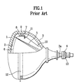
- FIG. 1 illustrates a side view with a partial cut away view of a related art color cathode ray tube.
- FIG. 1 there is a fluorescent material screen 2 having red, green, and blue fluorescent materials coated thereon on an inside surface of the panel 1 fitted to a front face of the cathode ray tube, and a funnel 3 at a rear of the panel 1 welded to the panel 1, and an electron gun 4 in a neck portion 3a of the funnel 3.
- a shadow mask 6 fixed to a frame 7 near to the fluorescent material screen 2 inside of the panel 1 for selecting colors of electron beams 5 emitted from the electron gun 4.
- the frame 7 is hung from a sidewall of the panel 1 as support springs 8 fixed to the frame 7 are inserted in stud pins 9 fixed to the sidewall of the panel 1.
- an inner shield 10 fixed to one side of the frame 7 by fastening springs 11 for protecting the electron beams 5 traveling toward the fluorescent material screen 2 from external geomagnetism.
- a magnet 13 having a plurality of poles on an outer circumference of the neck portion 3a for correcting a traveling path of the electron beams 5 to hit onto a required fluorescent material exactly, and a reinforcing band 12 strapped around an outer circumference of the cathode ray tube for preventing implosion of the cathode ray tube caused by external impact during operation of the cathode ray tube.
- the panel 1 forms a front face of a vacuum container to maintain an inside space of the cathode ray tube in a vacuum for smooth traveling of the electron beams.
- FIG. 2 illustrates a section of key parts of a related art panel, showing a skirt part 28 bent backward from an effective surface portion 20.
- the panel 1 with the skirt part 28 has a fixed total height 27, with reference to which the skirt part 28 is divided into an upper part 22 inclusive of the effective surface part 20 having a radius of outward curvature divided by a mold match line 21, an intermediate part 24 from the mold match line 21 to a break line 23, and a lower part 26 from the break line 23 to the seal edge line 25.
- An edge of the effective surface part 20 in the upper part 22 transits to the skirt part 28 through curvatures R and R', bland curvatures, wherein the outside bland curvature R' is connected to the mold match line 21 at an upper part angle 'a' of approx. 5° to a vertical line, the intermediate part 24 has an intermediate part angle 'b' of approx.
- the outward curved effective surface part of the related art panel with a consequential curved fluorescent screen on the effective surface, distorts a picture on the fluorescent screen and provides a sensing quality, it is a trend that the effective surface of the panel is formed flatter, to increase a ratio of the height of the upper part greater.
- the reinforcing band 32-strapped on an outside of the panel skirt part 28 is in general positioned starting from a boundary point of the bland curvature R' and the straight section of the upper part 22 of the skirt to entire intermediate part 24.
- the reinforcing band 32 has a section similar to a section of the panel skirt part 28, i.e., the reinforcing band 32 has a band body part 30 positioned at a lower part of the panel and a bent part 31 at the upper part 22 of the panel with reference to the mold match line 21 of the panel 1.
- the bent part 31 is bent at an angle identical to the angle 'a' of the upper part of the panel, and the band body part 30 is parallel to a cathode ray tube axis.
- the reinforcing band compresses the panel 1 to act against expansion acting outward during evacuation of the cathode ray tube in fabrication, to reduce a stress on the panel, which makes the structure stable.
- the related art cathode ray tube with the curved screen surface exhibits a maximum tension at a periphery of the effective surface part of the panel as stress concentrates thereto
- the flat cathode ray tube with a thickness of the effective surface relatively greater than the related art cathode ray tube exhibits a tension stress concentrated to the skirt part of the panel which is relatively thin, that makes the flat cathode ray tube weak for the stress, such that the suggested panel form and the reinforcing band have a problem of lacking for an actual implosion proof requirement.
- the increased panel upper part in the panel skirt part makes the contact between the panel upper part and the reinforcing band poor, to deteriorate implosion proof design efficiency.
- the shifting of a tension center on the reinforcing band to front according to the increased panel upper part may cause slip when the reinforcing band slips off the panel.
- the present invention is directed to an implosion proof panel in a cathode ray tube that addresses one or more of the problems due to limitations and disadvantages of the related art.
- the implosion proof panel in a cathode ray tube includes an effective surface part of a fluorescent screen formed on the panel, the panel with a substantially flat outside surface including, a skirt part starting from a periphery of the effective surface part to a seal edge line of the panel having an upper part, an intermediate part, and a lower part, the upper part and the intermediate part being divided by a mold match line, and a reinforcing band strapped around an outer circumference of the panel for preventing implosion of the cathode ray tube, wherein the panel meets the following conditions : Rdo/(USDdx1.75) ⁇ 35, and 0.7 ⁇ (MMLHd/OAH) ⁇ 0.9, where Rdo denotes a radius of curvature of the outside surface of the panel in a diagonal direction, USDd denotes a length of the effective surface part of the panel in the diagonal direction,
- an implosion proof panel in a cathode ray tube including an effective surface part of a fluorescent screen formed on the panel, and the panel with a substantially flat outside surface including, a skirt part bent substantially at a right angle starting from a periphery of the effective surface part to a seal edge line of the panel through a mold match line, wherein the panel meets the following conditions.
- Rdo denotes a radius of curvature of the outside surface of the panel in a diagonal direction
- USDd denotes a length of the effective surface part of the panel in the diagonal direction
- MMLHU denotes a height from a center of the outside surface of the panel to the mold match line of the panel
- CFT denotes a thickness of the panel at the center.
- FIG. 4 illustrates a section of key parts of a panel structure in a flat cathode ray tube in accordance with a preferred embodiment of the present invention.
- a rectangular panel 400 includes a panel inside surface part 404 positioned at an inside of the panel 400 with a radius Rdi of curvature, a panel front surface part 401 positioned at a front of the panel 400 with a radius Rdo of curvature, and a skirt part 403 formed substantially straight from an end of the front part 401 to a seal edge line 402.
- An effective surface part USDd having fluorescent material screen is formed at the front surface part 401, and a mold match line 406 is formed at a position higher than a position of an intersection 'q' between a vertical line 405 drawn from an end of the effective surface part USDd and the panel inside surface 404.
- the panel has an upper part 407a with a height made smaller as a mold match line 407 moves up toward the panel front surface formed above the mold match line 406, and an intermediate part 408a with a height made greater as the height of the upper part 407a of the panel is made smaller is formed below the mold match line 406.
- a break line 409 formed below the mold match line 406 of the panel forms a lower boundary of the intermediate part 408a, and a lower part 410a of the panel is formed between the break line 409 and the seal edge line 402 formed below the break line 409.
- the panel 400 has skirt parts 403 on opposite sides thereof, which can be divided in the same fashion. That is, the skirt part 403 may be divided into a skirt top part 407b starting from the end of the effective surface part USDd to the mold match line 408 to have a dimension the same with the height of the upper part 407a of the panel, a skirt middle part 408b continued from the skirt top part 407b to the break line 409, and a bottom part 410b continued from the skirt middle part 408b and extended to the seal edge line 402.
- the foregoing panel 400 is required to meet design criteria shown below for providing a maximum implosion proof efficiency.
- Rdo denotes a radius of curvature of the outside surface of the panel
- USDd denotes a length of the effective surface part of the panel having the screen formed thereon in a diagonal direction.
- MMLHu denotes a height from the center of the outside surface of the panel to the mold match line 406
- MMLHd denotes a height from the seal edge line 402 to the mold match line 406
- OAH denotes a total height of the panel.
- MMLHd and OAH have the following relation. 0.7 ⁇ (MMLHd/OAH) ⁇ 0.9
- the implosion proof panel in a cathode ray tube of the present invention can suppress implosion of the panel during or after fabrication to provide a panel of a high implosion proof performance without cost or weight of the cathode ray tube increased as a thickness of the skirt top part is increased or strengthening the reinforcing band for compensating an efficiency deterioration of the reinforcing band caused by a related art panel structure for solving the problem of weakening of the panel to a stress as the front part of the panel is made flat, thereby permitting to reduce a panel weight increased as a size of the flat cathode ray tube become larger, to allow to provide a light flat cathode ray tube, and to prevent the reinforcing band from slipping off the panel as the upper part of the panel is increased as the front part of the panel is made flat.
Landscapes
- Vessels, Lead-In Wires, Accessory Apparatuses For Cathode-Ray Tubes (AREA)
Abstract
Description
To achieve these and other advantages and in accordance with the purpose of the present invention, as embodied and broadly described, the implosion proof panel in a cathode ray tube, the cathode ray tube includes an effective surface part of a fluorescent screen formed on the panel, the panel with a substantially flat outside surface including, a skirt part starting from a periphery of the effective surface part to a seal edge line of the panel having an upper part, an intermediate part, and a lower part, the upper part and the intermediate part being divided by a mold match line, and a reinforcing band strapped around an outer circumference of the panel for preventing implosion of the cathode ray tube, wherein the panel meets the following conditions :
Rdo/(USDdx1.75)≥35, and 0.7≤(MMLHd/OAH)≤0.9,
where Rdo denotes a radius of curvature of the outside surface of the panel in a diagonal direction, USDd denotes a length of the effective surface part of the panel in the diagonal direction, MMLHd denotes a height from the seal edge line to the mold match line of the panel, and OAH denotes a total height of the panel.
Rdo/(USDdx1.75)≥35, and 0.5≤(MMLHu/CFT)≤3.0,
Where, Rdo denotes a radius of curvature of the outside surface of the panel in a diagonal direction, USDd denotes a length of the effective surface part of the panel in the diagonal direction, MMLHU denotes a height from a center of the outside surface of the panel to the mold match line of the panel, and CFT denotes a thickness of the panel at the center.
Claims (6)
- A panel for a cathode ray tube, comprising:an effective surface part of a fluorescent screen formed on the panel;the panel with a substantially flat outside surface including a skirt part starting from a periphery of the effective surface part to a seal edge line of the panel having an upper part, an intermediate part, and a lower part, the upper part and the intermediate part being divided by a mold match line,wherein the panel meets the following conditions:
Rdo/(USDdx1.75)≥35, and 0.7≤(MMLHd/OAH) ≤ 0.9,
where Rdo denotes a radius of curvature of the outside surface of the panel in a disgonal direction, USDd denotes a length of the effective surface part of the panel in the diagonal direction, MMLHd denotes a height from the seal edge line to the mold match line of the panel, and OAH denotes a total height of the panel. - A panel as claimed in claim 1, wherein the panel meets the following condition:
1.32≤(CFT+Zi-Zo)/CFT≤2.0
where Zi denotes a height from a center of the inside surface of the panel to a 'q' point, and Zo denotes a height from a center of the outside surface of the panel to a 'p' point, CFT denotes a thickness of the panel at the center of the panel, the 'p' denotes an end point of the USDd on the outside surface of the panel, and the 'q' denotes a point of intersection between a vertical line to the USDd drawn from the 'p' point with the inside surface of the panel. - A panel for a cathode ray tube, comprising:an effective surface part of a fluorescent screen formed on the panel; and,the panel with a substantially flat outside surface including a skirt part bent substantially at a right angle starting from a periphery of the effective surface part to a seal edge line of the panel through a mold match line,wherein the panel meets the following conditions:
Rdo/ (USDdx1.75)≥35, and 0.5 ≤ (MMLHu/CFT) ≤3.0 ,
where Rdo denotes a radius of curvature of the outside surface of the panel in a diagonal direction, USDd denotes a length of the effective surface part of the panel in the diagonal direction, MMLHU denotes a height from a center of the outside surface of the panel to the mold match line of the panel, and CFT denotes a thickness of the panel at the center. - A panel as claimed in claim 3, wherein the panel meets the following condition:
1.32≤(CFT+Zi-Zo)/CFT≤2.0
where Zi denotes a height from a center of the inside surface of the panel to a 'q' point, and Zo denotes a height from a center of the outside surface of the panel to a 'p' point, CFT denotes a thickness of the panel at the center of the panel, the 'p' denotes an end point of the USDd on the outside surface of the panel, and the 'q' denotes a point of intersection between a vertical line to the USDd drawn from the 'p' point with the inside surface of the panel. - A panel as claimed in any of claims 1 to 4, further comprising a reinforcing band strapped around an outer circumference of the panel for preventing implosion of the cathode ray tube.
- A cathode ray tube comprising the panel of any of claims 1 to 5.
Applications Claiming Priority (2)
| Application Number | Priority Date | Filing Date | Title |
|---|---|---|---|
| KR10-2000-0024042A KR100364695B1 (en) | 2000-05-04 | 2000-05-04 | Anti-Explosion type Panel of Braun tube |
| KR2000024042 | 2000-05-04 |
Publications (2)
| Publication Number | Publication Date |
|---|---|
| EP1152451A2 true EP1152451A2 (en) | 2001-11-07 |
| EP1152451A3 EP1152451A3 (en) | 2006-04-19 |
Family
ID=36095681
Family Applications (1)
| Application Number | Title | Priority Date | Filing Date |
|---|---|---|---|
| EP01303762A Withdrawn EP1152451A3 (en) | 2000-05-04 | 2001-04-25 | Implosion proof panel in cathode ray tube |
Country Status (6)
| Country | Link |
|---|---|
| US (1) | US6509683B2 (en) |
| EP (1) | EP1152451A3 (en) |
| JP (1) | JP4480293B2 (en) |
| KR (1) | KR100364695B1 (en) |
| CN (1) | CN1323054A (en) |
| MY (1) | MY118669A (en) |
Cited By (3)
| Publication number | Priority date | Publication date | Assignee | Title |
|---|---|---|---|---|
| EP1333464A3 (en) * | 2002-01-03 | 2003-09-03 | LG Philips Displays Korea Co., Ltd. | Color cathode ray tube |
| US6693374B2 (en) | 2001-09-11 | 2004-02-17 | Lg Philips Displays Korea Co., Ltd. | Flat CRT panel |
| DE10322151B4 (en) * | 2002-05-17 | 2009-07-02 | Samsung Corning Precision Glass Co., Ltd., Gumi | Flat screen with improved implosion protection for use in a cathode ray tube |
Families Citing this family (8)
| Publication number | Priority date | Publication date | Assignee | Title |
|---|---|---|---|---|
| JP3417900B2 (en) * | 1999-02-15 | 2003-06-16 | 株式会社東芝 | Cathode ray tube |
| KR100400778B1 (en) * | 2001-11-10 | 2003-10-08 | 엘지.필립스디스플레이(주) | Color Cathode Ray Tube |
| JP3656250B2 (en) * | 2002-04-26 | 2005-06-08 | 日本電気硝子株式会社 | Glass articles for cathode ray tubes |
| KR100489606B1 (en) * | 2002-11-20 | 2005-05-17 | 엘지.필립스 디스플레이 주식회사 | Cathode Ray Tube |
| KR100524864B1 (en) * | 2003-02-10 | 2005-10-31 | 엘지.필립스 디스플레이 주식회사 | Color cathod-ray tube |
| CN1278365C (en) * | 2003-06-24 | 2006-10-04 | Lg飞利浦显示器(韩国)株式会社 | Improved cathode ray tube |
| US7309952B2 (en) * | 2003-08-29 | 2007-12-18 | Samsung Corning Co., Ltd. | Flat panel with blend round portion structure for use in a cathode ray tube |
| KR100554420B1 (en) * | 2003-11-27 | 2006-02-22 | 엘지.필립스 디스플레이 주식회사 | Colored cathode ray tube |
Family Cites Families (10)
| Publication number | Priority date | Publication date | Assignee | Title |
|---|---|---|---|---|
| US4021850A (en) * | 1975-10-20 | 1977-05-03 | Zenith Radio Corporation | Color television picture tubes with improved implosion protection system |
| FR2680045B1 (en) * | 1991-07-30 | 1994-04-01 | Hitachi Ltd | COLORED CATHODIC TUBE OF THE PERFORATED MASK TYPE. |
| JPH05163036A (en) * | 1991-12-10 | 1993-06-29 | Nippon Sheet Glass Co Ltd | Pressure vessel made of glass |
| JP3196273B2 (en) * | 1991-12-26 | 2001-08-06 | ソニー株式会社 | Explosion-proof band and cathode ray tube |
| DE69403095T2 (en) * | 1993-02-03 | 1997-11-13 | Philips Electronics Nv | Anti-implosion band for an electron beam tube |
| KR0165084B1 (en) * | 1994-09-14 | 1998-12-15 | 엄길용 | Panel glass for color cathode ray tube |
| US5606377A (en) * | 1995-10-10 | 1997-02-25 | Thomson Consumer Electronics, Inc. | CRT having an implosion protection band with brackets |
| JPH10241604A (en) * | 1997-02-27 | 1998-09-11 | Asahi Glass Co Ltd | Glass panel for cathode ray tube |
| TW497115B (en) * | 1998-04-28 | 2002-08-01 | Hitachi Ltd | Cathode ray tube |
| KR100267963B1 (en) * | 1998-08-17 | 2000-10-16 | 구자홍 | Cathode ray panel |
-
2000
- 2000-05-04 KR KR10-2000-0024042A patent/KR100364695B1/en not_active Expired - Fee Related
-
2001
- 2001-04-18 MY MYPI20011849A patent/MY118669A/en unknown
- 2001-04-24 US US09/840,237 patent/US6509683B2/en not_active Expired - Fee Related
- 2001-04-24 JP JP2001125376A patent/JP4480293B2/en not_active Expired - Lifetime
- 2001-04-25 CN CN01117202A patent/CN1323054A/en active Pending
- 2001-04-25 EP EP01303762A patent/EP1152451A3/en not_active Withdrawn
Cited By (4)
| Publication number | Priority date | Publication date | Assignee | Title |
|---|---|---|---|---|
| US6693374B2 (en) | 2001-09-11 | 2004-02-17 | Lg Philips Displays Korea Co., Ltd. | Flat CRT panel |
| EP1291899A3 (en) * | 2001-09-11 | 2004-05-06 | Lg.Philips Displays Korea Co., Ltd. | Flat CRT panel |
| EP1333464A3 (en) * | 2002-01-03 | 2003-09-03 | LG Philips Displays Korea Co., Ltd. | Color cathode ray tube |
| DE10322151B4 (en) * | 2002-05-17 | 2009-07-02 | Samsung Corning Precision Glass Co., Ltd., Gumi | Flat screen with improved implosion protection for use in a cathode ray tube |
Also Published As
| Publication number | Publication date |
|---|---|
| US6509683B2 (en) | 2003-01-21 |
| MY118669A (en) | 2004-12-31 |
| JP4480293B2 (en) | 2010-06-16 |
| JP2001357800A (en) | 2001-12-26 |
| KR20010100645A (en) | 2001-11-14 |
| EP1152451A3 (en) | 2006-04-19 |
| KR100364695B1 (en) | 2003-02-06 |
| CN1323054A (en) | 2001-11-21 |
| US20020024291A1 (en) | 2002-02-28 |
Similar Documents
| Publication | Publication Date | Title |
|---|---|---|
| EP1152451A2 (en) | Implosion proof panel in cathode ray tube | |
| US6583546B2 (en) | Color cathode ray tube | |
| JP2004031305A (en) | Cathode ray tube | |
| US6664723B1 (en) | Shadow mask in color cathode ray tube | |
| US6335594B2 (en) | Frame assembly in flat cathode ray tube | |
| US6534909B1 (en) | Implosion protection band for color cathode ray tube | |
| JP3457563B2 (en) | Color picture tube | |
| US6628062B1 (en) | CRT panel having specified inner surface arc curvatures | |
| US6683403B2 (en) | Panel for flat screen type CRT | |
| US6472807B1 (en) | Braun tube frame having long and short sides of a specified height | |
| US6806632B2 (en) | Mask in color cathode ray tube | |
| KR0116741Y1 (en) | Deflection yoke of bobbin static equipment | |
| KR100331533B1 (en) | Color Ray Tube | |
| KR100295793B1 (en) | Safety band for CRT | |
| US20010043038A1 (en) | Frame in cathode ray tube | |
| JP3272278B2 (en) | Color cathode ray tubes, heat shrink bands and steel plates for heat shrink bands | |
| KR100422051B1 (en) | Deflection yoke | |
| JP3381615B2 (en) | Color cathode ray tube | |
| KR100210893B1 (en) | Color crt | |
| KR100626885B1 (en) | Cathode ray tube | |
| JP2000306528A (en) | Cathode-ray tube | |
| US7176611B2 (en) | Color cathode ray tube | |
| KR100301665B1 (en) | Flat Brown Tube Band | |
| KR100404575B1 (en) | A Flat Type CRT | |
| JP3021346B2 (en) | Cathode ray tube |
Legal Events
| Date | Code | Title | Description |
|---|---|---|---|
| PUAI | Public reference made under article 153(3) epc to a published international application that has entered the european phase |
Free format text: ORIGINAL CODE: 0009012 |
|
| AK | Designated contracting states |
Kind code of ref document: A2 Designated state(s): AT BE CH CY DE DK ES FI FR GB GR IE IT LI LU MC NL PT SE TR |
|
| AX | Request for extension of the european patent |
Free format text: AL;LT;LV;MK;RO;SI |
|
| PUAL | Search report despatched |
Free format text: ORIGINAL CODE: 0009013 |
|
| AK | Designated contracting states |
Kind code of ref document: A3 Designated state(s): AT BE CH CY DE DK ES FI FR GB GR IE IT LI LU MC NL PT SE TR |
|
| AX | Request for extension of the european patent |
Extension state: AL LT LV MK RO SI |
|
| 17P | Request for examination filed |
Effective date: 20060619 |
|
| 17Q | First examination report despatched |
Effective date: 20060724 |
|
| AKX | Designation fees paid |
Designated state(s): DE FR GB NL |
|
| GRAP | Despatch of communication of intention to grant a patent |
Free format text: ORIGINAL CODE: EPIDOSNIGR1 |
|
| STAA | Information on the status of an ep patent application or granted ep patent |
Free format text: STATUS: THE APPLICATION IS DEEMED TO BE WITHDRAWN |
|
| 18D | Application deemed to be withdrawn |
Effective date: 20080411 |