EP1152437A1 - Magnet roller - Google Patents
Magnet roller Download PDFInfo
- Publication number
- EP1152437A1 EP1152437A1 EP00971823A EP00971823A EP1152437A1 EP 1152437 A1 EP1152437 A1 EP 1152437A1 EP 00971823 A EP00971823 A EP 00971823A EP 00971823 A EP00971823 A EP 00971823A EP 1152437 A1 EP1152437 A1 EP 1152437A1
- Authority
- EP
- European Patent Office
- Prior art keywords
- magnetic
- pole
- magnet
- magnet pieces
- roller
- Prior art date
- Legal status (The legal status is an assumption and is not a legal conclusion. Google has not performed a legal analysis and makes no representation as to the accuracy of the status listed.)
- Withdrawn
Links
- 238000005304 joining Methods 0.000 claims description 57
- 230000005415 magnetization Effects 0.000 claims description 55
- 230000004907 flux Effects 0.000 abstract description 56
- 230000002708 enhancing effect Effects 0.000 abstract 1
- 238000004026 adhesive bonding Methods 0.000 description 30
- 239000006247 magnetic powder Substances 0.000 description 30
- 230000000052 comparative effect Effects 0.000 description 22
- 229910052761 rare earth metal Inorganic materials 0.000 description 13
- 150000002910 rare earth metals Chemical class 0.000 description 12
- 229920005989 resin Polymers 0.000 description 12
- 239000011347 resin Substances 0.000 description 12
- 229910045601 alloy Inorganic materials 0.000 description 10
- 239000000956 alloy Substances 0.000 description 10
- 239000011230 binding agent Substances 0.000 description 9
- 238000005259 measurement Methods 0.000 description 9
- 229910000859 α-Fe Inorganic materials 0.000 description 8
- 238000002156 mixing Methods 0.000 description 7
- 238000000465 moulding Methods 0.000 description 5
- 230000002093 peripheral effect Effects 0.000 description 5
- 239000013078 crystal Substances 0.000 description 4
- 238000004519 manufacturing process Methods 0.000 description 4
- 239000008188 pellet Substances 0.000 description 4
- 150000001875 compounds Chemical class 0.000 description 3
- 238000001125 extrusion Methods 0.000 description 3
- 239000000696 magnetic material Substances 0.000 description 3
- -1 polyethylene Polymers 0.000 description 3
- 239000004800 polyvinyl chloride Substances 0.000 description 3
- 229920000915 polyvinyl chloride Polymers 0.000 description 3
- 229910052712 strontium Inorganic materials 0.000 description 3
- 229920000219 Ethylene vinyl alcohol Polymers 0.000 description 2
- 229910017061 Fe Co Inorganic materials 0.000 description 2
- 239000004677 Nylon Substances 0.000 description 2
- 239000004734 Polyphenylene sulfide Substances 0.000 description 2
- DQXBYHZEEUGOBF-UHFFFAOYSA-N but-3-enoic acid;ethene Chemical compound C=C.OC(=O)CC=C DQXBYHZEEUGOBF-UHFFFAOYSA-N 0.000 description 2
- 239000005038 ethylene vinyl acetate Substances 0.000 description 2
- 239000004715 ethylene vinyl alcohol Substances 0.000 description 2
- 230000001771 impaired effect Effects 0.000 description 2
- 238000001746 injection moulding Methods 0.000 description 2
- 239000000314 lubricant Substances 0.000 description 2
- 229920001778 nylon Polymers 0.000 description 2
- 229920001200 poly(ethylene-vinyl acetate) Polymers 0.000 description 2
- 229920001707 polybutylene terephthalate Polymers 0.000 description 2
- 229920000139 polyethylene terephthalate Polymers 0.000 description 2
- 239000005020 polyethylene terephthalate Substances 0.000 description 2
- 229920000069 polyphenylene sulfide Polymers 0.000 description 2
- 239000000843 powder Substances 0.000 description 2
- CIOAGBVUUVVLOB-UHFFFAOYSA-N strontium atom Chemical compound [Sr] CIOAGBVUUVVLOB-UHFFFAOYSA-N 0.000 description 2
- RNFJDJUURJAICM-UHFFFAOYSA-N 2,2,4,4,6,6-hexaphenoxy-1,3,5-triaza-2$l^{5},4$l^{5},6$l^{5}-triphosphacyclohexa-1,3,5-triene Chemical compound N=1P(OC=2C=CC=CC=2)(OC=2C=CC=CC=2)=NP(OC=2C=CC=CC=2)(OC=2C=CC=CC=2)=NP=1(OC=1C=CC=CC=1)OC1=CC=CC=C1 RNFJDJUURJAICM-UHFFFAOYSA-N 0.000 description 1
- QLZJUIZVJLSNDD-UHFFFAOYSA-N 2-(2-methylidenebutanoyloxy)ethyl 2-methylidenebutanoate Chemical compound CCC(=C)C(=O)OCCOC(=O)C(=C)CC QLZJUIZVJLSNDD-UHFFFAOYSA-N 0.000 description 1
- 229910052692 Dysprosium Inorganic materials 0.000 description 1
- JHWNWJKBPDFINM-UHFFFAOYSA-N Laurolactam Chemical compound O=C1CCCCCCCCCCCN1 JHWNWJKBPDFINM-UHFFFAOYSA-N 0.000 description 1
- 229910052779 Neodymium Inorganic materials 0.000 description 1
- 229920000299 Nylon 12 Polymers 0.000 description 1
- 239000004952 Polyamide Substances 0.000 description 1
- 239000004698 Polyethylene Substances 0.000 description 1
- 239000004793 Polystyrene Substances 0.000 description 1
- 229910052777 Praseodymium Inorganic materials 0.000 description 1
- 229910052772 Samarium Inorganic materials 0.000 description 1
- BLRPTPMANUNPDV-UHFFFAOYSA-N Silane Chemical compound [SiH4] BLRPTPMANUNPDV-UHFFFAOYSA-N 0.000 description 1
- RTAQQCXQSZGOHL-UHFFFAOYSA-N Titanium Chemical compound [Ti] RTAQQCXQSZGOHL-UHFFFAOYSA-N 0.000 description 1
- 239000000853 adhesive Substances 0.000 description 1
- 230000001070 adhesive effect Effects 0.000 description 1
- 229910052782 aluminium Inorganic materials 0.000 description 1
- 150000001408 amides Chemical class 0.000 description 1
- 229910052787 antimony Inorganic materials 0.000 description 1
- 230000015572 biosynthetic process Effects 0.000 description 1
- 229910052797 bismuth Inorganic materials 0.000 description 1
- 229910052793 cadmium Inorganic materials 0.000 description 1
- 229910052804 chromium Inorganic materials 0.000 description 1
- 239000011248 coating agent Substances 0.000 description 1
- 238000000576 coating method Methods 0.000 description 1
- 239000000470 constituent Substances 0.000 description 1
- 229910052802 copper Inorganic materials 0.000 description 1
- 239000007822 coupling agent Substances 0.000 description 1
- 230000000694 effects Effects 0.000 description 1
- 239000003822 epoxy resin Substances 0.000 description 1
- UFRKOOWSQGXVKV-UHFFFAOYSA-N ethene;ethenol Chemical compound C=C.OC=C UFRKOOWSQGXVKV-UHFFFAOYSA-N 0.000 description 1
- 239000005042 ethylene-ethyl acrylate Substances 0.000 description 1
- 229920006244 ethylene-ethyl acrylate Polymers 0.000 description 1
- 239000003063 flame retardant Substances 0.000 description 1
- 229910052733 gallium Inorganic materials 0.000 description 1
- 229910052732 germanium Inorganic materials 0.000 description 1
- 229910052737 gold Inorganic materials 0.000 description 1
- 229910052735 hafnium Inorganic materials 0.000 description 1
- RZXDTJIXPSCHCI-UHFFFAOYSA-N hexa-1,5-diene-2,5-diol Chemical compound OC(=C)CCC(O)=C RZXDTJIXPSCHCI-UHFFFAOYSA-N 0.000 description 1
- 229910052738 indium Inorganic materials 0.000 description 1
- 229910052741 iridium Inorganic materials 0.000 description 1
- JEIPFZHSYJVQDO-UHFFFAOYSA-N iron(III) oxide Inorganic materials O=[Fe]O[Fe]=O JEIPFZHSYJVQDO-UHFFFAOYSA-N 0.000 description 1
- 238000004898 kneading Methods 0.000 description 1
- 229910052745 lead Inorganic materials 0.000 description 1
- 229910052748 manganese Inorganic materials 0.000 description 1
- 239000000463 material Substances 0.000 description 1
- 238000002844 melting Methods 0.000 description 1
- 230000008018 melting Effects 0.000 description 1
- 229910052753 mercury Inorganic materials 0.000 description 1
- 238000000034 method Methods 0.000 description 1
- 239000000203 mixture Substances 0.000 description 1
- 229910052750 molybdenum Inorganic materials 0.000 description 1
- 229910001172 neodymium magnet Inorganic materials 0.000 description 1
- 229910052759 nickel Inorganic materials 0.000 description 1
- 229910052758 niobium Inorganic materials 0.000 description 1
- 229910052762 osmium Inorganic materials 0.000 description 1
- 230000003647 oxidation Effects 0.000 description 1
- 238000007254 oxidation reaction Methods 0.000 description 1
- 229910052763 palladium Inorganic materials 0.000 description 1
- 238000007747 plating Methods 0.000 description 1
- 229910052697 platinum Inorganic materials 0.000 description 1
- 229920002647 polyamide Polymers 0.000 description 1
- 229920000647 polyepoxide Polymers 0.000 description 1
- 229920000573 polyethylene Polymers 0.000 description 1
- 229920002223 polystyrene Polymers 0.000 description 1
- 238000000197 pyrolysis Methods 0.000 description 1
- 229910052702 rhenium Inorganic materials 0.000 description 1
- 229910052703 rhodium Inorganic materials 0.000 description 1
- 229910052707 ruthenium Inorganic materials 0.000 description 1
- 239000000523 sample Substances 0.000 description 1
- 229920006395 saturated elastomer Polymers 0.000 description 1
- 229910052706 scandium Inorganic materials 0.000 description 1
- 229910000077 silane Inorganic materials 0.000 description 1
- 229910052710 silicon Inorganic materials 0.000 description 1
- 229910052709 silver Inorganic materials 0.000 description 1
- 239000003381 stabilizer Substances 0.000 description 1
- 239000000126 substance Substances 0.000 description 1
- 239000012756 surface treatment agent Substances 0.000 description 1
- 229910052715 tantalum Inorganic materials 0.000 description 1
- 229910052713 technetium Inorganic materials 0.000 description 1
- 229920005992 thermoplastic resin Polymers 0.000 description 1
- 229920001187 thermosetting polymer Polymers 0.000 description 1
- 229910052718 tin Inorganic materials 0.000 description 1
- 229910052719 titanium Inorganic materials 0.000 description 1
- 229910052721 tungsten Inorganic materials 0.000 description 1
- 229920006337 unsaturated polyester resin Polymers 0.000 description 1
- 229910052720 vanadium Inorganic materials 0.000 description 1
- 229910052725 zinc Inorganic materials 0.000 description 1
- 229910052726 zirconium Inorganic materials 0.000 description 1
Images




Classifications
-
- G—PHYSICS
- G03—PHOTOGRAPHY; CINEMATOGRAPHY; ANALOGOUS TECHNIQUES USING WAVES OTHER THAN OPTICAL WAVES; ELECTROGRAPHY; HOLOGRAPHY
- G03G—ELECTROGRAPHY; ELECTROPHOTOGRAPHY; MAGNETOGRAPHY
- G03G15/00—Apparatus for electrographic processes using a charge pattern
- G03G15/06—Apparatus for electrographic processes using a charge pattern for developing
- G03G15/08—Apparatus for electrographic processes using a charge pattern for developing using a solid developer, e.g. powder developer
- G03G15/09—Apparatus for electrographic processes using a charge pattern for developing using a solid developer, e.g. powder developer using magnetic brush
- G03G15/0921—Details concerning the magnetic brush roller structure, e.g. magnet configuration
-
- H—ELECTRICITY
- H01—ELECTRIC ELEMENTS
- H01F—MAGNETS; INDUCTANCES; TRANSFORMERS; SELECTION OF MATERIALS FOR THEIR MAGNETIC PROPERTIES
- H01F7/00—Magnets
- H01F7/02—Permanent magnets [PM]
- H01F7/0231—Magnetic circuits with PM for power or force generation
- H01F7/0252—PM holding devices
- H01F7/0268—Magnetic cylinders
Definitions
- the present invention relates to a magnet roller, and relates to a magnet roller in which a plurality of magnet pieces are joined at joining faces.
- magnet rollers are employed in for example copiers of the electrophotographic type, facsimile machines and laser printers.
- An example of such a magnet roller is the type, called the "joined type", in which the magnetic field pattern is formed by joining a plurality of magnet pieces which are magnetized with their magnetic grains aligned unidirectionally.
- Joined type magnet rollers are employed in developing devices for high picture quality, since they make possible the formation of a sharp magnetic field pattern.
- high magnetic force has come to be required even for poles other than the specified magnetic pole (developing pole), such as for example the pole for restricting the layer thickness of the developer; thus high magnetic force has come to be required in two or more magnetic poles in a single magnet roller.
- developer pole such as for example the pole for restricting the layer thickness of the developer
- high magnetic force has come to be required in two or more magnetic poles in a single magnet roller.
- four magnet pieces would be necessary in order to provide magnetic poles of high magnetic force.
- the number of magnet pieces was thereby further increased, further increasing the difficulty of improving productivity of the magnet roller, and making it more difficult to lower production costs.
- the present invention was made in view of the above problems, an object thereof being to provide a magnet roller wherein picture quality can be further improved by raising the magnetic flux density of the specified magnetic pole and/or other magnetic poles, and wherein a magnetic pole pattern with improved magnetic flux density of this specified magnetic pole and/or other magnetic poles can be achieved with low cost.
- a magnet roller according to the present invention wherein a plurality of magnet pieces are mounted at the periphery of a shaft by joining at joining faces, peaks of magnetic poles are generated on the lines of extension of the joining faces by setting the directions of orientation magnetization of adjacent magnet pieces facing the joining faces, the respective joining faces of the plurality of magnet pieces being made to coincide with roller radial directions of this magnet roller.
- the respective joining faces of the plurality of magnet pieces are made to coincide with roller radial directions and the orientation magnetization directions of adjacent magnet pieces are set facing the joining faces. Consequently, repulsive magnetic fields are generated at the joining faces, and the peaks of magnetic poles can be generated on the lines of extension of the joining faces.
- the peaks of the magnetic poles are caused to be generated on the lines of extension of the joining faces by making the respective joining faces of the plurality of magnet pieces coincide with radial directions of the roller. Consequently, the number of magnet pieces can be made the same as the number of magnetic poles required or can be restricted to the number of magnetic poles required +1.
- the sum of the angles of the orientation magnetization directions of at least one set of the adjacent magnet pieces is set at 30o to 140o.
- the magnetic flux density of for example the specified magnetic pole can therefore be made sufficiently large.
- the orientation magnetization directions of at least one set of the adjacent magnet pieces are made to converge towards the outside of the joining face.
- the magnetic path length is made longer, thereby increasing the coefficient of permeance and making it possible to generate a repulsive magnetic field in most efficient manner.
- the magnetic flux density of for example the specified magnetic pole can thereby be raised even further.
- Figure 1 is a perspective view of a magnet roller illustrating a first embodiment of the present invention.
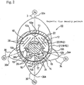
- Figure 2 is likewise a cross-sectional view thereof, showing the magnetic flux density pattern of the magnet roller.
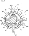
- Figure 3 is a cross-sectional view of a magnet roller illustrating a second embodiment of the present invention.
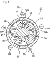
- Figure 4 is a cross-sectional view of a magnet roller illustrating a third embodiment of the present invention.
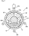
- Figure 5 is a cross-sectional view of a magnet roller illustrating a fourth embodiment of the present invention.
- Figure 6 is a cross-sectional view of a magnet roller illustrating Comparative Example 1.
- Figure 7 is a cross-sectional view of a magnet roller illustrating Comparative Example 2.
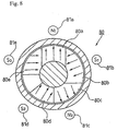
- Figure 8 is a cross-sectional view of a magnet roller illustrating Comparative Example 3.
- magnet roller 10 of the first embodiment is constituted by joining first to fourth magnet pieces 12, 14, 16 and 18 to the periphery of shaft 20, and installing these in a freely rotatable cylindrical sleeve 21.
- the arrangement is such that there is no mutual contact between the inner peripheral surface of the sleeve and the outer peripheral surface of the magnet.
- the respective joining faces 13, 15, 17 and 19 of the first to second magnet pieces 12, 14, 16 and 18 are made to coincide in the radial direction of the roller and the orientation magnetization directions 22, 24, 26, 28 (see Figure 2) of adjacent magnet pieces are set in position respectively facing joining faces 13, 15, 17 and 19; peaks 32a, 34a, 36a, 38a of magnetic poles 32, 34, 36 and 38 (see Figure 2) are thereby generated on the lines of extension of joining faces 13, 15, 17 and 19.
- the cross-sectional shape of shaft 20 could be any desired shape such as circular, elliptical, square or pentagonal etc and it could be of either magnetic or nonmagnetic material.
- the orientation magnetization direction 22 is arranged at 40o with respect to gluing face 12a on the side of the N pole and is arranged at 30o with respect to the gluing face 12b on the side of the S pole.
- the orientation magnetization direction 24 is arranged at 80o with respect to gluing face 14a on the side of the N pole and is arranged at 30o with respect to the gluing face 14b on the side of the S pole.
- the orientation magnetization direction 26 is arranged at 80o with respect to gluing face 16a on the side of the N pole and is arranged at 30o with respect to the gluing face 16b on the side of the S pole.
- the orientation magnetization direction 28 is arranged at 40o with respect to gluing face 18a on the side of the N pole and is arranged at 30o with respect to the gluing face 18b on the side of the S pole.
- the sum of the orientation magnetization angles is 80o (40o + 40o). It was found that the effect of a repulsive magnetic field is generated if the sum of the orientation magnetization angles is 30o or more. With this in view, the magnetic flux density was measured, varying the sum of the orientation magnetization directions by altering the orientation magnetization directions of the magnet pieces 12 and 18 in Figure 2. As shown in Figure 9, the result was that it was found that when the sum of the orientation magnetization directions is 30o to 140o, the magnetic flux density is 850 G or more, the greatest repulsive magnetic field being generated when the sum of the orientation magnetization angles was 80o.
- the sum of the orientation magnetization angles is then 60o (30o + 30o). By making the sum of the orientation magnetization angles at least 30o, a repulsive magnetic field can be generated and the magnetic flux density raised.
- the sum of the orientation magnetization angles is then 160o (80o + 80o). By making the sum of the orientation magnetization angles at least 30o, a repulsive magnetic field can be generated and the magnetic flux density raised.
- the sum of the orientation magnetization angles is then 60o (30o + 30o). By making the sum of the orientation magnetization angles at least 30o, a repulsive magnetic field can be generated and the magnetic flux density raised.
- the joining faces 13, 15, 17 and 19 of the first to fourth magnet pieces 12, 14, 16 and 18 are made to coincide in the radial direction of the roller and the orientation magnetization directions 22, 24, 26, 28 of adjacent magnet pieces are set in position facing joining faces 13, 15, 17 and 19; peaks 32a, 34a, 36a, 38a of magnetic poles 32, 34, 36 and 38 can thereby be generated on the lines of extension of joining faces 13, 15, 17 and 19.
- magnetic poles 32, 34, 36, 38 by forming magnetic poles 32, 34, 36, 38 by the repulsive magnetic fields at joining faces 13, 15, 17, 19, high magnetic force can be obtained at a plurality of magnetic poles (specified magnetic pole and other magnetic poles) 32, 34, 36, 38.
- peaks 32a, 34a, 36a, 38a were generated of the magnetic poles 32, 34, 36, 38 on the lines of extension of joining faces 13, 15, 17, 19, by making joining faces 13, 15, 17, 19 of the first to the fourth magnet pieces 12, 14, 16, 18 coincide with the radial directions of the roller.
- the number (four) of magnet pieces 12, 14, 16 and 18 can therefore be kept to the same number (four) as the number of required magnetic poles 32, 34, 36 and 38.
- first to fourth magnet pieces 12, 14, 16, 18 is fan shaped
- the angle of opening of the fan may be suitably set in accordance with the required magnetic flux density and/or shape of the magnetic flux density pattern.
- the faces of first to fourth magnet pieces 12, 14, 16 and 18 facing the shaft 20 may be suitably set being for example arcuate or linear, in accordance with the shape of shaft 20.
- orientation magnetization may be applied concurrently with molding, or magnetization may be effected after molding.
- the directions of orientation magnetization of first to fourth magnet pieces 12, 14, 16 and 18 may be set in accordance with the required magnetic flux density and/or shape of the magnetic flux density pattern.
- First to fourth magnet pieces 12, 14, 16 and 18 are formed by mixing and dispersing resin binder such as nylon (5 weight% to 50 weight%) with for example strontium-based ferrite magnetic powder (50 weight% to 95 weight%), melting and kneading, molding into pellets, then forming these pellets into fan shape by injection molding or extrusion molding.
- resin binder such as nylon (5 weight% to 50 weight%) with for example strontium-based ferrite magnetic powder (50 weight% to 95 weight%)
- a mixed magnetic powder obtained by mixing a magnetic powder constituted by ferrite magnetic powder and a rare earth magnetic powder, or a rare earth magnetic powder on its own may be employed.
- Such mixed magnetic powder or rare earth magnetic powder may be applied only to the magnet pieces that are to constitute the magnetic poles where high magnetic force is required, or may be applied to all the magnetic pieces.
- rare earth magnetic powders examples include: R (rare earth)-Fe-N based alloys, R-Fe-B based alloys, R-Co based alloys, or R-Fe-Co based alloys etc.
- exchange spring magnetic powders including a soft magnetic phase and a hard magnetic phase and having a structure in which there is a mutual exchange action of the magnetization of the two phases are preferred.
- Exchange spring magnetic powders have a low coercive force (to be described) originating from the soft magnetic phase and have a high residual magnetic flux density (to be described) originating from the mutual exchange action, so they can be made to have a desired high magnetic force and they also have much better resistance to oxidation than conventional rare earth magnetic powders; thus, rusting can be prevented without applying a surface coating such as plating and, in addition, since the exchange spring magnetic powder contains a large quantity of soft magnetic phase, its Curie point is high (400oC or more), so its limiting temperature of use is high (at least 200oC) and it shows little temperature dependence of residual magnetization.
- rare earth element R a combination of one or two or more of preferably Sm or Nd or in addition Pr, Dy, or Tb etc may be employed.
- one or two or more of elements such as Co, Ni, Cu, Zn, Ga, Ge, Al, Si, Sc, Ti, V, Cr, Mn, Zr, Nb, Mo, Tc, Ru, Rh, Pd, Ag, Cd, In, Sn, Sb, Hf, Ta, W, Re, Os, Ir, Pt, Au, Hg, T1, Pb or Bi may be added.
- the exchange spring magnetic powder it is preferable to employ a powder wherein R-Fe-B compound is employed as the hard magnetic phase and Fe phase or Fe-B compound phase is employed as the soft magnetic layer, or a powder wherein R-Fe-N compound is used as the hard magnetic phase and Fe phase as the soft magnetic layer.
- exchange spring magnetic powders such as Nd-Fe-B based alloys (soft magnetic phase: Fe-B Alloy, Fe), Sm-Fe-N based alloys (soft magnetic phase: Fe), Nd-Fe-Co-Cu-Nd-B based alloys (soft magnetic phase: Fe-B Alloy, Fe etc), or Nd-Fe-Co based alloys (soft magnetic phase: Fe etc) are preferable.
- Nd-Fe-B based alloys soft magnetic phase: Fe-B Alloy, Fe
- Sm-Fe-N based alloys soft magnetic phase: Fe
- Nd-Fe-Co-Cu-Nd-B based alloys soft magnetic phase: Fe-B Alloy, Fe etc
- Nd-Fe-Co based alloys soft magnetic phase: Fe etc
- Nd4Fe80B20 alloy soft magnetic phase: Fe-B Alloy, Fe
- Sm2Fe17N3 alloy soft magnetic phase: Fe
- anisotropic or isotropic ferrite magnetic powder having a chemical formula represented by MO.Fe 2 O 3 may be employed, where, in this formula, for M, a suitable selection is made of one or two or more of for example Sr, Ba or lead.
- resin binder (50 weight% to 95 weight%): (5 wt% to 50 weight%)
- silane-based or titanate-based coupling agent added as surface treatment agent
- an amide-based lubricating agent added as a lubricating agent to obtain good fluidity of the molten magnetic material
- the insufficiency of magnetic powder causes the magnetic properties of the magnet roller to be impaired so that the desired high magnetic force is not obtained, and if the content is more than 95 weight%, insufficiency of binder causes the molding properties of the magnet pieces to be impaired.
- resin binders examples include: ethylene-ethylacrylate resin, polyamide, polyethylene, polystyrene, PET (polyethylene terephthalate), PBT (polybutylene terephthalate), PPS (polyphenylene sulfide), EVA (ethylene vinyl acetate), EVOH (ethylene vinyl alcohol), and PVC (polyvinyl chloride) etc; a mixture of one or two or more of these may be employed.
- the main unit is a resin binder comprising nylon or the like
- a resin binder system having flexibility comprising a thermoplastic resin such as PVC, or a thermosetting resin such as epoxy resin or unsaturated polyester resin is even more preferable.
- coercive force means the inherent coercive force (iHc), and is the external magnetic field in opposition to the repulsive magnetic field produced by the residual magnetization when a residual magnetization of half this amount is maintained.
- Residual magnetic flux density (Br) means the magnetic force from the condition of saturated magnetic flux density i.e. the magnetic flux density when the magnetic field is removed.
- Exchange spring magnetization means that, when a large amount of soft magnetic phase is present in a magnet, the magnetizations of the crystal grains having soft magnetic characteristics and crystal grains having hard magnetic characteristics are mutually linked by the mutual exchange action, so that inversion of the magnetization of the soft magnetic crystal grains is impeded by the magnetization of the hard magnetic crystal grains, with the result that a characteristic is displayed as if the soft magnetic phase were not present.
- an exchange spring magnet contains a large amount of soft magnetic phase whose residual magnetic flux density is larger than that of the hard magnetic phase (usually a rare earth magnet consists solely of this phase) and whose coercive force is small, a magnet of small coercive force and high residual magnetic flux density is obtained.
- the magnet roller 40 of the second embodiment comprises first to fourth magnet pieces 42, 14, 16 and 48.
- First magnetic piece 42 is subjected to orientation magnetization that converges as shown by arrow 44 from the two faces: S pole side gluing face 42b and shaft 20 side bottom face 20a towards the apex 43 formed by the N pole side gluing face 42a and peripheral face 42c.
- fourth magnetic piece 48 is subjected to orientation magnetization that converges as shown by arrow 49 from the two faces: S pole side gluing face 48b and shaft 20 side bottom face 20a towards the apex 42d formed by the N pole side gluing face 48a and peripheral face 48c.
- magnet roller 50 according to the third embodiment comprises six first to sixth magnet pieces 51, 52, 53, 54, 55 and 56.
- first to sixth magnet pieces 51, 52, 53, 54, 55 and 56 By setting the orientation magnetization directions of first to sixth magnet pieces 51, 52, 53, 54, 55, and 56 as shown in Figure 4, three peaks of magnetic flux density are formed on the lines of extension of joining faces 58a, 58b, 58c and two peaks of magnetic flux density are formed at locations which are not on these lines of extension (i.e. a total of five locations).
- ⁇ is set to be less than 15 because if gap ⁇ is made larger than 15o the magnetic resistance becomes large and the magnetic force obtained is lowered.
- Magnet roller 10 of the first embodiment shown in Figure 2 was manufactured under the following conditions.
- the resin binder 10 weight% of nylon 12 was used and for the magnetic powder 90 weight% of strontium ferrite (SrO.6Fe 2 O 3 ) was used; these were mixed, melted and kneaded and molded into pellet shape before being extrusion molded to obtain four first to fourth magnet pieces 12, 14, 16 and 18 as shown in Figure 2 (diameter ⁇ of external periphery 13.6, diameter ⁇ of internal periphery 6, length 320 mm); concurrently with the molding, these magnet pieces were subjected to orientation magnetization with a magnetic field of 8 KOe to 15 KOe in the directions indicated by arrows 22, 24, 26, 28 (the leading end of the arrow represents the N pole).
- strontium ferrite SrO.6Fe 2 O 3
- Magnet roller 10 was manufactured by gluing these magnet pieces 12, 14, 16 and 18 to shaft 20 (magnetic material: SUM22; outer peripheral face diameter ⁇ : 6) by means of adhesive.
- a probe (sensor) was arranged at a location 8 mm distant from the center of the magnet roller 10 obtained, and the peak magnetic force of the respective magnetic poles measured using a gauss-meter whilst rotating magnet roller 10.
- Magnet roller 40 of the second embodiment shown in Figure 3 was manufactured under the same conditions as in Practical Example 1.
- Magnet roller 50 of the third embodiment shown in Figure 4 was manufactured under the same conditions as in Practical Example 1.
- the number of magnet pieces was 6 (number of magnetic poles + 1), and the directions of orientation magnetization of the magnet pieces were as shown in Figure 4; otherwise, this Practical Example was the same as Practical Example 1.
- Magnet roller 60 of the fourth embodiment shown in Figure 5 was manufactured under the same conditions as in Practical Example 1.
- Magnet roller 70 was constructed of the magnet pieces 70a to 70d shown in Figure 6. The positions of the magnetic poles (magnetic flux density peak positions) were the same as in the case of Practical Example 1.
- the results of the measurement were that the magnetic flux densities of N1 pole 75a, S1 pole 75b, N2 pole 75c and S2 pole 75d were respectively 850G, 550G, 650G and 600G.
- a magnet roller 76 was constructed with a roller body 76a of integrally molded type as shown in Figure 7.
- the positions of the magnetic poles were the same as in the case of Practical Example 1.
- the results of the measurement were that the magnetic flux densities of N1 pole 78a, S1 pole 78b, N2 pole 78c and S2 pole 78d were respectively 800G, 600G, 550G and 600G.
- a magnet roller 80 was constructed of the magnet pieces 80a to 80d shown in Figure 8.
- the results of the measurement were that the magnetic flux densities of N1 pole 81a, S1 pole 81b, N2 pole 81c, S2 pole 81d and S3 pole 81e were respectively 850G, 750G, 700G, 600G and 550G.
- the results of the measurement were that the magnetic flux densities of N1 pole 69a, S1 pole 69b, N2 pole 69c and S2 pole 69d were respectively 850G, 680G, 800G and 680G.
- gap ⁇ was set to 7o and 15o.
- the magnetic flux density was somewhat lower than in the case of Practical Example 1, in both cases a magnetic flux density of more than 900G could be ensured, the magnetic flux density being higher than in the Comparative Examples.
- the magnetic flux density was 850G.
- the magnetic flux density can be raised to 900G or more at the specified magnetic pole, and can be raised to 700 to 800G or more at the other magnetic poles.
- peaks of magnetic poles are generated on the lines of extension of the joining faces by setting the directions of orientation magnetization of adjacent magnet pieces facing the joining faces, the respective joining faces of the plurality of magnet pieces being made to coincide with roller radial directions of this magnet roller.
- the respective joining faces of the plurality of magnet pieces are directed in the roller radial directions and the orientation magnetization directions of adjacent magnet pieces are set facing the joining faces. Consequently, repulsive magnetic fields are generated at the joining faces, and the peaks of magnetic poles can be generated on the lines of extension of the joining faces.
- the peaks of the magnetic poles are caused to be generated on the lines of extension of the joining faces by directing the respective joining faces of the plurality of magnet pieces in radial directions of the roller. Consequently, the number of magnet pieces can be made the same as the number of magnetic poles required or can be restricted to the number of magnetic poles required +1.
- the sum of the angles of the orientation magnetization directions of at least one set of the adjacent magnet pieces is set at 30o to 140o.
- the magnetic flux density of for example the specified magnetic pole can therefore be made sufficiently large.
- the orientation magnetization directions of at least one set of the adjacent magnet pieces are made to converge towards the outside of the joining face.
- orientation magnetization directions of at least one set of the adjacent magnet pieces converge towards the outside of the joining face, it can be made possible to generate a repulsive magnetic field in most efficient manner.
- the magnetic flux density of for example the specified magnetic pole can thereby be raised even further.
Landscapes
- Physics & Mathematics (AREA)
- General Physics & Mathematics (AREA)
- Electromagnetism (AREA)
- Engineering & Computer Science (AREA)
- Power Engineering (AREA)
- Magnetic Brush Developing In Electrophotography (AREA)
- Manufacturing Cores, Coils, And Magnets (AREA)
Abstract
Description
| Magnetic flux density (G) | ||||||
| Practical Example 1 | N1 pole | S1 pole | N2 pole | S2 pole | S3 pole | Fig. 2 |
| 950G | 700G | 780G | 700G | - | ||
| Practical Example 2 | 970G | 730G | 790G | 720G | - | Fig. 3 |
| Practical Example 3 | 950G | 750G | 900G | 700G | 700G | Fig. 4 |
| Practical Example 4 | 940G | 700G | 790G | 700G | - | Fig. 5 |
| Practical Example 5 | 900G | 690G | 790G | 690G | - | Fig. 5 |
| Comparative example 1 | 850G | 550G | 650G | 600G | - | Fig. 6 |
| Comparative example 2 | 800G | 600G | 550G | 600G | - | Fig. 7 |
| Comparative Example 3 | 850G | 750G | 700G | 600G | 550G | Fig. 8 |
| Comparative Example 4 | 850G | 680G | 800G | 680G | - | Fig. 5 |
Claims (3)
- A magnet roller (10, 40, 50, 60) having a plurality of magnet pieces (12, 14, 16, 18, 42, 48, 51, 52, 53, 54, 55, 56, 62, 68) mounted at the periphery of a shaft (20) by joining at joining faces,
wherein, in this magnet roller (10, 40, 50, 60), peaks (32a, 34a, 36a, 38a) of magnetic poles (32, 34, 36, 38, 49a, 49b, 49c, 49d) are generated on the lines of extension of the joining faces (13, 15, 17, 19, 45) by setting the directions of orientation magnetization (22, 24, 26, 28, 44, 49) of adjacent magnet pieces (12, 14, 16, 18, 42, 48) facing the joining faces (13, 15, 17, 19, 45), the respective joining faces (13, 15, 17, 19, 45) of the plurality of magnet pieces (12, 14, 16, 18, 42, 48, 51, 52, 53, 54, 55, 56, 62, 68) being made to coincide with roller radial directions. - The magnet roller according to claim 1, wherein the sum of the angles of the orientation magnetization directions (22, 28) of at least one set of said adjacent magnet pieces (12, 14, 16, 18) is set at 30º to 140º.
- The magnet roller according to claim 1, wherein the orientation magnetization directions (44, 48) of at least one set of said adjacent magnet pieces (42, 14, 16, 48) are made to converge towards the outside of joining face (45).
Applications Claiming Priority (3)
| Application Number | Priority Date | Filing Date | Title |
|---|---|---|---|
| JP31933099 | 1999-11-10 | ||
| JP31933099A JP2001135518A (en) | 1999-11-10 | 1999-11-10 | Magnet roller |
| PCT/JP2000/007811 WO2001035426A1 (en) | 1999-11-10 | 2000-11-07 | Magnet roller |
Publications (2)
| Publication Number | Publication Date |
|---|---|
| EP1152437A1 true EP1152437A1 (en) | 2001-11-07 |
| EP1152437A4 EP1152437A4 (en) | 2003-01-29 |
Family
ID=18108989
Family Applications (1)
| Application Number | Title | Priority Date | Filing Date |
|---|---|---|---|
| EP00971823A Withdrawn EP1152437A4 (en) | 1999-11-10 | 2000-11-07 | Magnet roller |
Country Status (4)
| Country | Link |
|---|---|
| US (1) | US6762665B1 (en) |
| EP (1) | EP1152437A4 (en) |
| JP (1) | JP2001135518A (en) |
| WO (1) | WO2001035426A1 (en) |
Families Citing this family (10)
| Publication number | Priority date | Publication date | Assignee | Title |
|---|---|---|---|---|
| JP4746789B2 (en) * | 2001-08-01 | 2011-08-10 | 株式会社ブリヂストン | Mold for resin magnet molding and method for manufacturing resin magnet molded product |
| JP4338082B2 (en) * | 2004-01-29 | 2009-09-30 | Tdk株式会社 | Magnet roll and developing device |
| JPWO2005119374A1 (en) * | 2004-06-04 | 2008-04-03 | 株式会社カネカ | Magnet roller |
| US8500615B2 (en) * | 2007-01-11 | 2013-08-06 | Ricoh Company, Ltd. | Magnetic roller and manufacturing method thereof, developer carrier, development device, processing cartridge, and image forming apparatus |
| US8270114B2 (en) | 2008-02-08 | 2012-09-18 | International Business Machines Corporation | Magnetically biased tilting roller bearing tape guidance |
| US7839598B2 (en) * | 2008-02-08 | 2010-11-23 | International Business Machines Corporation | Balanced linkage actuation of tape head |
| US8228635B2 (en) | 2008-02-08 | 2012-07-24 | International Business Machines Corporation | Friction engaged tilting roller bearing tape guidance |
| US7649710B2 (en) * | 2008-02-08 | 2010-01-19 | International Business Machines Corporation | Moving magnet actuation of tape head |
| CN102893222B (en) * | 2010-06-02 | 2015-03-25 | Pm技研株式会社 | Magnet roller |
| JP7749986B2 (en) * | 2021-08-31 | 2025-10-07 | 富士フイルムビジネスイノベーション株式会社 | Magnet body, magnet part, and method for manufacturing the magnet body |
Family Cites Families (5)
| Publication number | Priority date | Publication date | Assignee | Title |
|---|---|---|---|---|
| CS213709B1 (en) * | 1979-03-13 | 1982-04-09 | Vaclav Landa | Anizotropous permanent magnets |
| US4557582A (en) * | 1982-04-02 | 1985-12-10 | Canon Kabushiki Kaisha | Magnet roll |
| JP2545602B2 (en) * | 1989-02-22 | 1996-10-23 | 日立金属株式会社 | Magnet roll |
| JP3116890B2 (en) * | 1997-03-06 | 2000-12-11 | 株式会社ブリヂストン | Magnet roller and method of manufacturing magnet roller |
| JP3567722B2 (en) * | 1997-06-09 | 2004-09-22 | 鐘淵化学工業株式会社 | Magnet roller |
-
1999
- 1999-11-10 JP JP31933099A patent/JP2001135518A/en active Pending
-
2000
- 2000-11-07 EP EP00971823A patent/EP1152437A4/en not_active Withdrawn
- 2000-11-07 US US09/868,907 patent/US6762665B1/en not_active Expired - Lifetime
- 2000-11-07 WO PCT/JP2000/007811 patent/WO2001035426A1/en not_active Ceased
Also Published As
| Publication number | Publication date |
|---|---|
| EP1152437A4 (en) | 2003-01-29 |
| JP2001135518A (en) | 2001-05-18 |
| US6762665B1 (en) | 2004-07-13 |
| WO2001035426A1 (en) | 2001-05-17 |
Similar Documents
| Publication | Publication Date | Title |
|---|---|---|
| US6762665B1 (en) | Magnet roller | |
| JP3828369B2 (en) | Magnet roller | |
| JP3799994B2 (en) | Magnet roller | |
| JP3564374B2 (en) | Magnet roller | |
| JP2000323322A (en) | Magnet roller | |
| JP2005300935A (en) | Magnet roller or its manufacturing method | |
| JP2004087644A (en) | Magnet roller | |
| JPH01115109A (en) | Magnet roll manufacturing method | |
| JP2001143923A (en) | Method of manufacturing magnet roller and method of manufacturing magnet piece | |
| JP2003015424A (en) | Magnet roller | |
| JP4556649B2 (en) | Magnet roller manufacturing method | |
| JP2007027220A (en) | Resin magnet compact, manufacturing method thereof, and magnetizing yoke | |
| JP2003086421A (en) | Magnet roller | |
| JP2001274015A (en) | Magnet roller | |
| JP2001142302A (en) | Magnet roller | |
| JP2864608B2 (en) | Manufacturing method of magnet roll | |
| US6703915B1 (en) | Magnet roller | |
| JPH071727B2 (en) | Anisotropic resin magnet and manufacturing method thereof | |
| JP4743575B2 (en) | Developing roll | |
| JP4572663B2 (en) | Magnet roller | |
| EP1253604A1 (en) | Magnet roller | |
| JP2000331823A (en) | Magnet roller | |
| JP3116890B2 (en) | Magnet roller and method of manufacturing magnet roller | |
| JPH05291027A (en) | Magnet roll and manufacturing method thereof | |
| JPS62235703A (en) | Anisotropic resin magnet |
Legal Events
| Date | Code | Title | Description |
|---|---|---|---|
| PUAI | Public reference made under article 153(3) epc to a published international application that has entered the european phase |
Free format text: ORIGINAL CODE: 0009012 |
|
| 17P | Request for examination filed |
Effective date: 20010718 |
|
| AK | Designated contracting states |
Kind code of ref document: A1 Designated state(s): AT BE CH CY DE DK ES FI FR GB GR IE IT LI LU MC NL PT SE TR |
|
| A4 | Supplementary search report drawn up and despatched |
Effective date: 20021213 |
|
| RIC1 | Information provided on ipc code assigned before grant |
Ipc: 7H 01F 7/02 B Ipc: 7G 03G 15/09 A |
|
| RBV | Designated contracting states (corrected) |
Designated state(s): DE FR GB IT NL |
|
| 17Q | First examination report despatched |
Effective date: 20051219 |
|
| GRAP | Despatch of communication of intention to grant a patent |
Free format text: ORIGINAL CODE: EPIDOSNIGR1 |
|
| STAA | Information on the status of an ep patent application or granted ep patent |
Free format text: STATUS: THE APPLICATION IS DEEMED TO BE WITHDRAWN |
|
| 18D | Application deemed to be withdrawn |
Effective date: 20090415 |