EP1152434A1 - Cell flow diverter and flow diverter/vortex generator assembly for BWR spacers - Google Patents
Cell flow diverter and flow diverter/vortex generator assembly for BWR spacers Download PDFInfo
- Publication number
- EP1152434A1 EP1152434A1 EP01303953A EP01303953A EP1152434A1 EP 1152434 A1 EP1152434 A1 EP 1152434A1 EP 01303953 A EP01303953 A EP 01303953A EP 01303953 A EP01303953 A EP 01303953A EP 1152434 A1 EP1152434 A1 EP 1152434A1
- Authority
- EP
- European Patent Office
- Prior art keywords
- flow
- cells
- flow diverter
- spacer
- cylindrical tube
- Prior art date
- Legal status (The legal status is an assumption and is not a legal conclusion. Google has not performed a legal analysis and makes no representation as to the accuracy of the status listed.)
- Withdrawn
Links
- 125000006850 spacer group Chemical group 0.000 claims abstract description 77
- 238000011144 upstream manufacturing Methods 0.000 claims abstract description 7
- 230000001154 acute effect Effects 0.000 claims description 7
- 239000003758 nuclear fuel Substances 0.000 claims description 7
- 239000000446 fuel Substances 0.000 abstract description 43
- 239000011800 void material Substances 0.000 abstract description 4
- 210000004027 cell Anatomy 0.000 description 98
- XLYOFNOQVPJJNP-UHFFFAOYSA-N water Substances O XLYOFNOQVPJJNP-UHFFFAOYSA-N 0.000 description 14
- 238000009835 boiling Methods 0.000 description 13
- 230000000295 complement effect Effects 0.000 description 5
- 238000011065 in-situ storage Methods 0.000 description 3
- 238000003466 welding Methods 0.000 description 3
- 230000005465 channeling Effects 0.000 description 2
- 239000002826 coolant Substances 0.000 description 2
- 238000004519 manufacturing process Methods 0.000 description 2
- 230000002093 peripheral effect Effects 0.000 description 2
- 230000009286 beneficial effect Effects 0.000 description 1
- 210000002421 cell wall Anatomy 0.000 description 1
- 238000006243 chemical reaction Methods 0.000 description 1
- 238000010276 construction Methods 0.000 description 1
- 238000006073 displacement reaction Methods 0.000 description 1
- 238000009434 installation Methods 0.000 description 1
- 239000000463 material Substances 0.000 description 1
- 239000002184 metal Substances 0.000 description 1
Images




Classifications
-
- G—PHYSICS
- G21—NUCLEAR PHYSICS; NUCLEAR ENGINEERING
- G21C—NUCLEAR REACTORS
- G21C3/00—Reactor fuel elements and their assemblies; Selection of substances for use as reactor fuel elements
- G21C3/30—Assemblies of a number of fuel elements in the form of a rigid unit
- G21C3/32—Bundles of parallel pin-, rod-, or tube-shaped fuel elements
- G21C3/322—Means to influence the coolant flow through or around the bundles
-
- Y—GENERAL TAGGING OF NEW TECHNOLOGICAL DEVELOPMENTS; GENERAL TAGGING OF CROSS-SECTIONAL TECHNOLOGIES SPANNING OVER SEVERAL SECTIONS OF THE IPC; TECHNICAL SUBJECTS COVERED BY FORMER USPC CROSS-REFERENCE ART COLLECTIONS [XRACs] AND DIGESTS
- Y02—TECHNOLOGIES OR APPLICATIONS FOR MITIGATION OR ADAPTATION AGAINST CLIMATE CHANGE
- Y02E—REDUCTION OF GREENHOUSE GAS [GHG] EMISSIONS, RELATED TO ENERGY GENERATION, TRANSMISSION OR DISTRIBUTION
- Y02E30/00—Energy generation of nuclear origin
- Y02E30/30—Nuclear fission reactors
Definitions
- the present invention relates to a cell flow diverter for use on spacers of a boiling water nuclear reactor for channeling flow through the spacer cells into a vortex generator or about a fuel rod passing through the spacer cell and flow diverter.
- the invention also relates to the combination of a cell flow diverter and vortex generator.
- each fuel bundle comprises an array of fuel rods passing through axially spaced spacers, all encompassed within a fuel channel.
- the fuel rods comprises full-length fuel rods with one or more part-length fuel rods interspersed at predetermined locations within the array of full-length rods.
- Part-length fuel rods terminate at an elevation within the fuel bundle typically below one or more of the uppermost spacers of the bundle.
- the termination of the part-length fuel rods creates voids in the upper sections of the fuel bundle bounded by adjacent full-length fuel rods.
- Various swirler vane arrangements have been proposed for disposition on the upper ends of the part-length fuel rods or on the spacers to circulate the boiling water/moderator in the void regions.
- a flow diverter for diverting flow between cells of a spacer for flow within the diverter wherein the diverter channels the flow into a vortex generator for distributing boiling water/moderator onto and into the interstices of adjacent full-length fuel rods adjacent void regions or channel the flow between the cells of the spacer onto a fuel rod passing through the spacer cell mounting the flow diverter.
- the flow diverter preferably includes a generally cylindrical tube for overlying a cell of a spacer.
- the flow diverter tube includes a plurality of tabs projecting laterally from the tube generally at perpendicular locations about the axis of the tube.
- Each tab extends diagonally relative to the rectilinear array of spacer cells into spaces between adjacent cells, i.e., between the rows and columns of cells. For example, each tab extends diagonally into the space between adjacent cells a distance such that the outer edge of the tab extends beyond a straight line interconnecting center lines of diagonally adjacent cells.
- boiling water/moderator is diverted from the interstices of the spacer cells through the tubular diverter for flow in an axial downstream direction at a spacer cell location generally corresponding to the cell location of the diverter.
- One beneficial effect of this construction and location of the flow diverter is that the coolant flow increases in pressure and velocity as it passes through the flow diverter. This is particularly effective in "supercharging" the flow when the diverter is disposed about a fuel rod.
- the flow diverter is employed in conjunction with a vortex generator.
- a cylindrical tube is provided having a plurality of slits opening through a downstream end of the tube.
- slits opening through a downstream end of the tube.
- each vane defined by adjacent slits in the vortex generator tube is twisted such that one edge lies inboard of the circumference of the tube and the opposite edge lies along the circumference of the tube.
- Tube portions between the slits forming the vanes are removed.
- the tips of the vanes meet at the central axis of the vortex generator and may be welded to one another at that location.
- the slit size and shape of the vanes ensure that the vanes of the vortex generator do not extend laterally beyond the periphery of the vortex generator tube.
- the tube of the flow diverter is preferably provided with a series of circumferentially spaced slots.
- the base of the vortex generator is provided with spring tabs angled such that upon displacement of the vortex generator toward the flow diverter, e.g., downwardly onto the flow diverter, the spring tabs deflect first inwardly and then outwardly into the slots of the flow diverter to secure the vortex generator to the flow diverter.
- the flow diverter and vortex generator may have complementary threads whereby the vortex generator may be screwthreaded onto the flow diverter.
- the vanes and threads are configured such that the swirling of the flow afforded by the vortex generator is in swirl direction tending to tighten the vortex generator on the flow diverter.
- the flow diverter comprises a cylindrical tube wherein the tabs are struck from the tube for extension into the interstices between adjacent spacer cells with the vortex generator forming an integral part of the flow diverter tube.
- the vortex generator is similar to the embodiment first described above without its interconnection with the flow diverter.
- the flow diverter may be secured to the spacer, for example, by welding, in a cell location which receives a fuel rod.
- the boiling water/moderator flows from between the spacer cells into the tube of the diverter and into an annular space between the diverter and fuel rod to maintain flow contact with the fuel rod.
- a flow diverter for diverting flow between cells of a spacer in a nuclear fuel bundle into the diverter and in a downstream flow direction relative to the spacer, the spacer having a rectilinear array of cells, comprising a cylindrical tube for overlying a spacer cell and having an axis, a plurality of tabs projecting laterally from the cylindrical tube at perpendicular locations relative to one another about the axis for disposition in the spacer between diagonally adjacent cells of the rectilinear array thereof, the tabs forming with the axis acute angles for diverting flow through the spacer into the cylindrical tube.
- a flow diverter/spacer combination for diverting flow between cells of a spacer in a nuclear fuel bundle for flow within the diverter and in a downstream flow direction relative to the spacer, comprising a spacer having generally cylindrical side-by-side cells in cell positions arranged in parallel rows and parallel columns forming a generally rectilinear array of cells, the cells having parallel axes, a cylindrical tube overlying a cell and having an axis generally coincident with the axis of the cell, a plurality of tabs projecting laterally from the cylindrical tube at perpendicular locations relative to one another about the axis, each tab extending diagonally relative to the rectilinear array of columns and rows of the cells into spaces between diagonally adjacent cells, the tabs forming with the axis acute angles opening in an upstream direction for diverting flow through openings between the cells of the spacer into the cylindrical tube.
- a conventional boiling water/nuclear fuel bundle generally designated 10, comprised of a plurality of fuel rods 12 disposed in a rectilinear array thereof and extending between upper and lower tie plates 14 and 16, respectively.
- a plurality of spacers S are axially spaced one from the other at various elevations along the fuel bundle.
- the fuel rods and spacers are enclosed within a fuel channel 18.
- the boiling water/moderator flows upwardly through the fuel bundle about the fuel rods and through the cells of the spacers S, generating steam for the generation of power.
- part-length fuel rods 20 which terminate at their upper ends short of the upper tie plate and typically below one or more of the upper spacers. Also illustrated in Figure 1 are a plurality of conventional swirl vanes 22 disposed on the downstream side of the spacers at spacer cell locations above the part-length rods 20.
- FIG. 2 there is illustrated a representative spacer S which schematically illustrates cells in a rectilinear horizontal array of cells.
- the rectilinear array is characterized by perpendicularly related rows and columns of cells 24, represented by x and y axes, respectively, in Figure 2.
- a 10x10 array of spacer cells is shown with ten cells in each row (except for water rod locations, not shown).
- the cells may be of the ferrule type, i.e., short cylindrical tubes for receiving the fuel rods or may comprise other types such as disclosed in U.S. Patents Nos. 5,740,218 and 5,727,039. Suffice to say that the present invention can be used with different and various configurations of cells.
- each flow diverter 26 comprises a cylindrical tube 30, preferably corresponding in diameter, in the illustrated form, to the diameter of the cell 24 ( Figure 2).
- the flow diverter 26 includes a plurality of tabs 32 which project laterally outwardly of the tube 30.
- the tabs 32 are also inclined relative to the axis of the tube 30 in an upstream direction when disposed over a cell 24.
- the tabs 32 are inclined downwardly, as illustrated in Figures 2 and 3 and form acute angles with the axis of the tubular cells 24.
- the lateral margins 34 of each tab 32 are shaped complementary to the arcuate outside surfaces of diagonally adjacent cells as illustrated in Figure 5, while the distal ends 36 of the tabs 32 are likewise arcuately configured for engagement against a diagonally adjacent cell which lies both in a different row and column as the flow diverter.
- the tabs 32 may be interposed in the spaces between the orthogonally related rows and columns of spacer cells.
- the diverter may be welded to each of the adjacent cells in the corresponding column and row whereby the tabs 32 abut the adjacent cells.
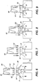
- the weld joints are denoted 35 in Figures 7-9.
- the distal ends 36 of the tabs 32 extend laterally outwardly of the diverter tube 30 a distance beyond a straight line 40 drawn between center lines of diagonally adjacent cells. That is, the distal ends 36 of tabs 32 extend beyond straight lines 40 extending between the center axes 42 of diagonally adjacent cells and preferably abut the cell walls of a second set of diagonally adjacent cells in columns and rows not common to the column and row containing the flow diverter. With this configuration, it will therefore be appreciated that the flow through the spaces between the diagonally adjacent cells is completely diverted into the tube 30 of the diverter 26.
- a vortex generator 28 formed of a generally cylindrical tube 50 of a diameter for reception within the tube 30 of the flow diverter 26.
- the lower end or base of the tube 50 has laterally outward spring tabs 52 having lower surfaces 53 inclined to the axis through the tube 50.
- a plurality of swirler vanes 60 are provided adjacent the upper end of the vortex generator 28.
- the vanes are formed by slitting the generally cylindrical tube 50 in an axial direction through one end thereof and twisting inwardly one edge of each vane 60.
- eight slits 61 are formed through the end of tube 50. Tube material between alternate pairs of slits is removed and the remaining vanes are twisted so that one edge inclines inwardly to meet at its end the inner edges of other vanes.
- the vanes lie within the tubular envelope defined by tube 50, i.e., the vanes do not extend outside the periphery of tube 50 and lie within its peripheral confines.
- the tip of each vane 60 along its inner edge contacts one another at an apex 62.
- the apices of the vane 60 may be welded at that location 62.
- the vanes impart a swirling motion to the boiling water/moderator flowing upwardly in the fuel bundle through the flow diverter 26 and into vortex generator 28, i.e., flowing in a downstream direction.
- a swirl-type flow above the assembly and in the void region above the part-length fuel rods is achieved.
- the spring tabs 52 can be deflected inwardly to release the vortex generator from the flow diverter in situ and even after irradiation.
- the flow diverter 26 is first applied over the upper or downstream end of a cell as illustrated in Figure 6.
- the tabs 32 extend between the diagonally adjacent cells and that their distal ends 36 are in contact with diagonally adjacent cells (Figure 5).
- Welds are formed between the sides of the tubes 30 and the adjoining cells 24 in the rows and columns to secure the flow diverter to the spacer.
- the vortex generator 28 is then displaced axially on top of the flow diverter as illustrated in Figure 8.
- the springs 52 deflect inwardly and then outwardly into slots 54 upon registration therewith to secure the vortex generator to the flow diverter as illustrated in Figure 9.
- the flow diverter 80 is constructed similarly as the flow diverter 26 except that, instead of slots 54, threads 81 are formed about the tube 30, the tabs 32 being identical as those of the previous embodiment.
- Vortex generator 82 is likewise formed similarly as the vortex generator 28, except that spring tabs 52 are omitted in favor of complementary threads 84.
- the vortex generator 82 thus may be threaded into the flow diverter 80 and released therefrom by unthreading action in situ and after irradiation.
- the vanes 60 of vortex generator 82 are formed similarly as the vanes of the prior embodiment.
- the threads 81 and 84 preferably comprise male/female threads, respectively, although the threads may be arranged vice-versa.
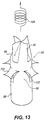
- FIG. 13-15 there is illustrated a combined flow diverter/vortex generator and cell assembly 96 formed of a single integral piece of tubular sheet metal stock.
- the tabs 100 of like configuration as the tabs 32 of the first embodiment are struck from the tubular body 98 to project laterally outwardly and at an angle to the tube axis as illustrated from a review of Figures 14 and 15.
- the tabs 100 have side and end configurations similarly as in the tabs 32 of the first embodiment, but leaving holes 102 in the tubular body 98 to receive the deflected flow generated by the tabs for flow in a downstream direction within the tubular body.
- the upper end of the tubular body 98 comprises the vortex generator 99 ( Figure 13) which includes vanes 60 constructed similarly as the vanes of the first embodiment.
- the lower tubular base of the assembly below the slots 102 forms a cell of the spacer disposed above a part-length fuel rod. That is, the tubular assembly 96 is substituted for a tubular cell 24 in the spacer S and forms an integral part therewith, i.e., by welding. Consequently, the boiling water/moderator flows in a downstream direction through the tubular body 98 and is joined by the deflected flow caused by the projecting tabs 100 for flow through the assembly and the vortex generator portion thereof.
- the vanes 60 impart the swirling motion to the flow, as represented by the circular arrow 108 in Figure 13, similarly as in the first embodiment.
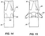
- Figure 14 illustrates the cuts 106 formed in the tubular body 98 such that the tabs may be struck and laterally projected from the body as illustrated in Figure 15.
- a flow diverter 120 for use in conjunction with a cell 24 which receives a fuel rod 12.
- the flow diverter 120 comprises a cylindrical or tubular body 122 similarly as the tube 30 of the first embodiment for securement on the top of a cell 24, also as in the embodiment of Figures 2-9.
- body 122 includes tabs 124 constructed similarly as tabs 32 and which project into the spaces between the cells. The boiling water/moderator is thus diverted from flowing between the cells into an annular space between the flow diverter 120 and a fuel rod 12 within the cell 24 thus increasing in flow velocity and pressure, e.g., "supercharging" the flow.
- the base of the flow diverter includes a plurality of upstream extending projections 128 whereby the flow diverter may be secured, for example, by welding along the upper margin of a cell of the spacer.
- the cell flow diverter 120 may be located at any position in the spacer where it is desirable to increase the flow about the fuel rod extending through that cell location.
- the tabs 124 can be cut to different lengths on opposite sides of one another, which when bent upwards would cause the coolant flow to swirl.
- the flow diverter 150 has tabs 152 which have long and short sides or edges 154 and 156, respectively. When the tabs 152 are struck from the diverter 150, the tab twists such that flow through the diverter not only increases in velocity but is also swirled in the direction of the long sides 154 of the tabs 152. Thus, the tabs 152 are twisted to provide a swirl-type flow.
Landscapes
- Physics & Mathematics (AREA)
- Engineering & Computer Science (AREA)
- Plasma & Fusion (AREA)
- General Engineering & Computer Science (AREA)
- High Energy & Nuclear Physics (AREA)
- Fuel Cell (AREA)
Abstract
A flow diverter (26) is provided for attachment to a spacer cell (24) above a
part-length fuel rod. The flow diverter includes a tubular base having a
plurality of laterally projecting tabs (32) extending in an upstream direction for
diverting flow from between the spacer cells into the volume above the spacer
void of a fuel rod. A vortex generator (28) is secured to or forms an integral
part with the flow diverter for swirling the flow onto and into the interstices of
laterally adjacent fuel rods. The flow diverter and vortex generator are formed
of tubular stock. The vanes (60) of the vortex generator are formed by
providing slits along the tubular stock and twisting alternating edges of the
stock inwardly to form the vanes.
Description
- The present invention relates to a cell flow diverter for use on spacers of a boiling water nuclear reactor for channeling flow through the spacer cells into a vortex generator or about a fuel rod passing through the spacer cell and flow diverter. The invention also relates to the combination of a cell flow diverter and vortex generator.
- In boiling water nuclear reactors, each fuel bundle comprises an array of fuel rods passing through axially spaced spacers, all encompassed within a fuel channel. The fuel rods comprises full-length fuel rods with one or more part-length fuel rods interspersed at predetermined locations within the array of full-length rods. Part-length fuel rods terminate at an elevation within the fuel bundle typically below one or more of the uppermost spacers of the bundle. As well known, the termination of the part-length fuel rods creates voids in the upper sections of the fuel bundle bounded by adjacent full-length fuel rods. Various swirler vane arrangements have been proposed for disposition on the upper ends of the part-length fuel rods or on the spacers to circulate the boiling water/moderator in the void regions. Certain problems are associated with these prior swirl vane arrangements which include difficulty of fabrication, attachment of the swirl vanes to the spacer, both during initial fabrication and in situ installation and removal of the swirl vane after fuel bundle irradiation. There is therefore a need for a flow diverter for channeling the flow into desired locations and particularly a flow diverter/vortex generator assembly for directing the boiling water/moderator flowing through the spacers and into the voids above part-length rods for flow about and into the interstices of adjacent upper regions of full-length fuel rods.
- In accordance with a preferred embodiment of the present invention, there is provided a flow diverter for diverting flow between cells of a spacer for flow within the diverter wherein the diverter channels the flow into a vortex generator for distributing boiling water/moderator onto and into the interstices of adjacent full-length fuel rods adjacent void regions or channel the flow between the cells of the spacer onto a fuel rod passing through the spacer cell mounting the flow diverter. The flow diverter preferably includes a generally cylindrical tube for overlying a cell of a spacer. The flow diverter tube includes a plurality of tabs projecting laterally from the tube generally at perpendicular locations about the axis of the tube. Each tab extends diagonally relative to the rectilinear array of spacer cells into spaces between adjacent cells, i.e., between the rows and columns of cells. For example, each tab extends diagonally into the space between adjacent cells a distance such that the outer edge of the tab extends beyond a straight line interconnecting center lines of diagonally adjacent cells. With the tab occupying the area between the diagonally adjacent cells and being angled laterally outwardly from the diverter in an axial upstream direction, boiling water/moderator is diverted from the interstices of the spacer cells through the tubular diverter for flow in an axial downstream direction at a spacer cell location generally corresponding to the cell location of the diverter. One beneficial effect of this construction and location of the flow diverter is that the coolant flow increases in pressure and velocity as it passes through the flow diverter. This is particularly effective in "supercharging" the flow when the diverter is disposed about a fuel rod.
- In a preferred embodiment of the present invention, the flow diverter is employed in conjunction with a vortex generator. In a first form of vortex generator, a cylindrical tube is provided having a plurality of slits opening through a downstream end of the tube. For example, where four vanes are to be provided, eight slits are provided and each vane defined by adjacent slits in the vortex generator tube is twisted such that one edge lies inboard of the circumference of the tube and the opposite edge lies along the circumference of the tube. Tube portions between the slits forming the vanes are removed. The tips of the vanes meet at the central axis of the vortex generator and may be welded to one another at that location. The slit size and shape of the vanes ensure that the vanes of the vortex generator do not extend laterally beyond the periphery of the vortex generator tube.
- To secure the vortex generator to the flow diverter, the tube of the flow diverter is preferably provided with a series of circumferentially spaced slots. The base of the vortex generator is provided with spring tabs angled such that upon displacement of the vortex generator toward the flow diverter, e.g., downwardly onto the flow diverter, the spring tabs deflect first inwardly and then outwardly into the slots of the flow diverter to secure the vortex generator to the flow diverter. In another form, the flow diverter and vortex generator may have complementary threads whereby the vortex generator may be screwthreaded onto the flow diverter. The vanes and threads are configured such that the swirling of the flow afforded by the vortex generator is in swirl direction tending to tighten the vortex generator on the flow diverter.
- In a further preferred embodiment hereof, the flow diverter comprises a cylindrical tube wherein the tabs are struck from the tube for extension into the interstices between adjacent spacer cells with the vortex generator forming an integral part of the flow diverter tube. The vortex generator is similar to the embodiment first described above without its interconnection with the flow diverter.
- In a still further form hereof, the flow diverter may be secured to the spacer, for example, by welding, in a cell location which receives a fuel rod. In this manner, the boiling water/moderator flows from between the spacer cells into the tube of the diverter and into an annular space between the diverter and fuel rod to maintain flow contact with the fuel rod.
- In a preferred embodiment according to the present invention, there is provided a flow diverter for diverting flow between cells of a spacer in a nuclear fuel bundle into the diverter and in a downstream flow direction relative to the spacer, the spacer having a rectilinear array of cells, comprising a cylindrical tube for overlying a spacer cell and having an axis, a plurality of tabs projecting laterally from the cylindrical tube at perpendicular locations relative to one another about the axis for disposition in the spacer between diagonally adjacent cells of the rectilinear array thereof, the tabs forming with the axis acute angles for diverting flow through the spacer into the cylindrical tube.
- In a further preferred embodiment according to the present invention, there is provided a flow diverter/spacer combination for diverting flow between cells of a spacer in a nuclear fuel bundle for flow within the diverter and in a downstream flow direction relative to the spacer, comprising a spacer having generally cylindrical side-by-side cells in cell positions arranged in parallel rows and parallel columns forming a generally rectilinear array of cells, the cells having parallel axes, a cylindrical tube overlying a cell and having an axis generally coincident with the axis of the cell, a plurality of tabs projecting laterally from the cylindrical tube at perpendicular locations relative to one another about the axis, each tab extending diagonally relative to the rectilinear array of columns and rows of the cells into spaces between diagonally adjacent cells, the tabs forming with the axis acute angles opening in an upstream direction for diverting flow through openings between the cells of the spacer into the cylindrical tube.
- The invention will now be described in greater detail, by way of example, with reference to the drawings, in which:-
- FIGURE 1 is a schematic perspective view with parts broken out and in cross-section of a conventional boiling water fuel bundle;
- FIGURE 2 is a schematic perspective view illustrating a spacer of a ferrule type having a flow diverter and vortex generator assembly constructed in accordance with a preferred embodiment of the present invention at specified cell locations;
- FIGURE 3 is a perspective view illustrating a preferred form of flow diverter and vortex generator prior to assembly with one another;
- FIGURE 4 is a view similar to Figure 3 illustrating the flow diverter and vortex generator in assembled condition;
- FIGURE 5 is a top plan view thereof;
- FIGURES 6-9 illustrate a sequence of steps for interconnecting the flow diverter, spacer cells and the vortex generator;
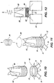
- FIGURE 10 is a perspective view of a flow diverter and vortex generator according to another preferred embodiment hereof;
- FIGURE 11 is a perspective view thereof in an assembled condition;
- FIGURE 12 is a side elevational view thereof in the assembled condition in a spacer;
- FIGURE 13 is a perspective view of a unitary cell flow diverter and vortex generator;
- FIGURES 14 and 15 illustrate the steps for forming the unitary flow diverter and vortex generator of Figure 13;
- FIGURE 16 is a perspective view of a spacer illustrating a flow diverter about a fuel rod through a spacer cell location; and
- FIGURE 17 is an exploded enlarged perspective view illustrating the flow diverter of Figure 16.
- FIGURE18 is another embodiment of the flow diverter of Figure 16.
-
- Referring now to the drawings, particularly to Figure 1, there is illustrated a conventional boiling water/nuclear fuel bundle, generally designated 10, comprised of a plurality of
fuel rods 12 disposed in a rectilinear array thereof and extending between upper andlower tie plates fuel channel 18. As conventional, the boiling water/moderator flows upwardly through the fuel bundle about the fuel rods and through the cells of the spacers S, generating steam for the generation of power. Also illustrated in Figure 1 are part-length fuel rods 20 which terminate at their upper ends short of the upper tie plate and typically below one or more of the upper spacers. Also illustrated in Figure 1 are a plurality ofconventional swirl vanes 22 disposed on the downstream side of the spacers at spacer cell locations above the part-length rods 20. - Referring to Figure 2, there is illustrated a representative spacer S which schematically illustrates cells in a rectilinear horizontal array of cells. For convenience, the rectilinear array is characterized by perpendicularly related rows and columns of
cells 24, represented by x and y axes, respectively, in Figure 2. In the illustrated spacer, a 10x10 array of spacer cells is shown with ten cells in each row (except for water rod locations, not shown). The cells may be of the ferrule type, i.e., short cylindrical tubes for receiving the fuel rods or may comprise other types such as disclosed in U.S. Patents Nos. 5,740,218 and 5,727,039. Suffice to say that the present invention can be used with different and various configurations of cells. - In Figure 2, there is illustrated a plurality of
flow diverters 26 in combination withvortex generators 28. Referring to Figure 3, eachflow diverter 26 comprises acylindrical tube 30, preferably corresponding in diameter, in the illustrated form, to the diameter of the cell 24 (Figure 2). Theflow diverter 26 includes a plurality oftabs 32 which project laterally outwardly of thetube 30. - The
tabs 32 are also inclined relative to the axis of thetube 30 in an upstream direction when disposed over acell 24. Thus, thetabs 32 are inclined downwardly, as illustrated in Figures 2 and 3 and form acute angles with the axis of thetubular cells 24. Thelateral margins 34 of eachtab 32 are shaped complementary to the arcuate outside surfaces of diagonally adjacent cells as illustrated in Figure 5, while thedistal ends 36 of thetabs 32 are likewise arcuately configured for engagement against a diagonally adjacent cell which lies both in a different row and column as the flow diverter. As best illustrated in Figure 5, with this configuration, thetabs 32 may be interposed in the spaces between the orthogonally related rows and columns of spacer cells. To secure theflow diverter 26 to the spacer, the diverter may be welded to each of the adjacent cells in the corresponding column and row whereby thetabs 32 abut the adjacent cells. The weld joints are denoted 35 in Figures 7-9. - Also as best seen in Figure 5, the distal ends 36 of the
tabs 32 extend laterally outwardly of the diverter tube 30 a distance beyond a straight line 40 drawn between center lines of diagonally adjacent cells. That is, the distal ends 36 oftabs 32 extend beyond straight lines 40 extending between the center axes 42 of diagonally adjacent cells and preferably abut the cell walls of a second set of diagonally adjacent cells in columns and rows not common to the column and row containing the flow diverter. With this configuration, it will therefore be appreciated that the flow through the spaces between the diagonally adjacent cells is completely diverted into thetube 30 of thediverter 26. - Also illustrated in Figures 2-5 is a
vortex generator 28 formed of a generallycylindrical tube 50 of a diameter for reception within thetube 30 of theflow diverter 26. The lower end or base of thetube 50 has laterallyoutward spring tabs 52 havinglower surfaces 53 inclined to the axis through thetube 50. At like spacing abouttube 30 ofdiverter 26 as thespring tabs 52 lie abouttube 50, there are provided a plurality ofslots 54 throughdiverter tube 30. By axially displacing thevortex generator 28 onto theflow diverter 26 as illustrated in sequence in Figures 8 and 9, thespring tabs 52 may be deflected first inwardly by engagement of theinclined surfaces 53 against the margin oftube 30 and then deflected outwardly in theslots 54 upon registration with the slots. The spring tabs/slot engagement thus maintain thevortex generator 28 assembled on the flow diverter 26 (Figure 4). - To generate a swirling flow through the flow diverter and vortex generator assembly, a plurality of
swirler vanes 60 are provided adjacent the upper end of thevortex generator 28. The vanes are formed by slitting the generallycylindrical tube 50 in an axial direction through one end thereof and twisting inwardly one edge of eachvane 60. For example, where fourvanes 60 are used, eightslits 61 are formed through the end oftube 50. Tube material between alternate pairs of slits is removed and the remaining vanes are twisted so that one edge inclines inwardly to meet at its end the inner edges of other vanes. By forming the vanes in this manner, the vanes lie within the tubular envelope defined bytube 50, i.e., the vanes do not extend outside the periphery oftube 50 and lie within its peripheral confines. Preferably, the tip of eachvane 60 along its inner edge contacts one another at an apex 62. The apices of thevane 60 may be welded at thatlocation 62. Thus, it will be appreciated that the vanes impart a swirling motion to the boiling water/moderator flowing upwardly in the fuel bundle through theflow diverter 26 and intovortex generator 28, i.e., flowing in a downstream direction. Thus, a swirl-type flow above the assembly and in the void region above the part-length fuel rods is achieved. Note that by employing a suitable tool, not shown, thespring tabs 52 can be deflected inwardly to release the vortex generator from the flow diverter in situ and even after irradiation. - To install the flow diverter/vortex generator, the
flow diverter 26 is first applied over the upper or downstream end of a cell as illustrated in Figure 6. Note that thetabs 32 extend between the diagonally adjacent cells and that theirdistal ends 36 are in contact with diagonally adjacent cells (Figure 5). Welds are formed between the sides of thetubes 30 and the adjoiningcells 24 in the rows and columns to secure the flow diverter to the spacer. Thevortex generator 28 is then displaced axially on top of the flow diverter as illustrated in Figure 8. Thus, as the lower end oftube 50 is received withintube 30, thesprings 52 deflect inwardly and then outwardly intoslots 54 upon registration therewith to secure the vortex generator to the flow diverter as illustrated in Figure 9. - Turning now to the embodiment hereof illustrated in Figures 10-12, the
flow diverter 80 is constructed similarly as theflow diverter 26 except that, instead ofslots 54,threads 81 are formed about thetube 30, thetabs 32 being identical as those of the previous embodiment.Vortex generator 82 is likewise formed similarly as thevortex generator 28, except thatspring tabs 52 are omitted in favor ofcomplementary threads 84. Thevortex generator 82 thus may be threaded into theflow diverter 80 and released therefrom by unthreading action in situ and after irradiation. Thevanes 60 ofvortex generator 82 are formed similarly as the vanes of the prior embodiment. Note also that the reaction force on thevortex generator 82 indicated by thearrow 86 resulting from swirling the flow in the direction illustrated by thearrow 88 in Figure 11 tends to tighten thethreads 84 of thevortex generator 82 about thethreads 81 of theflow diverter 80. Thethreads - Referring now to the embodiment hereof illustrated in Figures 13-15, there is illustrated a combined flow diverter/vortex generator and
cell assembly 96 formed of a single integral piece of tubular sheet metal stock. For example, thetabs 100 of like configuration as thetabs 32 of the first embodiment are struck from thetubular body 98 to project laterally outwardly and at an angle to the tube axis as illustrated from a review of Figures 14 and 15. Thetabs 100 have side and end configurations similarly as in thetabs 32 of the first embodiment, but leavingholes 102 in thetubular body 98 to receive the deflected flow generated by the tabs for flow in a downstream direction within the tubular body. The upper end of thetubular body 98 comprises the vortex generator 99 (Figure 13) which includesvanes 60 constructed similarly as the vanes of the first embodiment. In this form, the lower tubular base of the assembly below theslots 102 forms a cell of the spacer disposed above a part-length fuel rod. That is, thetubular assembly 96 is substituted for atubular cell 24 in the spacer S and forms an integral part therewith, i.e., by welding. Consequently, the boiling water/moderator flows in a downstream direction through thetubular body 98 and is joined by the deflected flow caused by the projectingtabs 100 for flow through the assembly and the vortex generator portion thereof. Thevanes 60 impart the swirling motion to the flow, as represented by thecircular arrow 108 in Figure 13, similarly as in the first embodiment. Figure 14 illustrates thecuts 106 formed in thetubular body 98 such that the tabs may be struck and laterally projected from the body as illustrated in Figure 15. - Referring to the final embodiment of the present invention illustrated in Figures 16 and 17, there is provided a
flow diverter 120 for use in conjunction with acell 24 which receives afuel rod 12. Theflow diverter 120 comprises a cylindrical ortubular body 122 similarly as thetube 30 of the first embodiment for securement on the top of acell 24, also as in the embodiment of Figures 2-9. Thus,body 122 includestabs 124 constructed similarly astabs 32 and which project into the spaces between the cells. The boiling water/moderator is thus diverted from flowing between the cells into an annular space between theflow diverter 120 and afuel rod 12 within thecell 24 thus increasing in flow velocity and pressure, e.g., "supercharging" the flow. In Figure 17, it will be appreciated that the base of the flow diverter includes a plurality of upstream extendingprojections 128 whereby the flow diverter may be secured, for example, by welding along the upper margin of a cell of the spacer. Thecell flow diverter 120 may be located at any position in the spacer where it is desirable to increase the flow about the fuel rod extending through that cell location. - Also, the
tabs 124 can be cut to different lengths on opposite sides of one another, which when bent upwards would cause the coolant flow to swirl. Thus, as illustrated in Figure 18, theflow diverter 150 hastabs 152 which have long and short sides oredges tabs 152 are struck from thediverter 150, the tab twists such that flow through the diverter not only increases in velocity but is also swirled in the direction of thelong sides 154 of thetabs 152. Thus, thetabs 152 are twisted to provide a swirl-type flow. - For the sake of good order, various aspects of the invention are set out in the following clauses:-
- 1. A flow diverter for diverting flow between cells of a spacer in a nuclear
fuel bundle into the diverter and in a downstream flow direction relative to the
spacer, the spacer having a rectilinear array of cells, comprising:
- a cylindrical tube for overlying a spacer cell and having an axis, a plurality of tabs projecting laterally from said cylindrical tube at perpendicular locations relative to one another about said axis for disposition in the spacer between diagonally adjacent cells of the rectilinear array thereof;
- said tabs forming with said axis acute angles for diverting flow through the spacer into said cylindrical tube.
- 2. A flow diverter according to Clause 1 wherein said tabs are integral with the cylindrical tube.
- 3. A flow diverter according to Clause 1 wherein said tabs have tips and arcuate side edges terminating in said tips, said side edges being arcuate for substantial conformance with arcuate side edges of diagonally adjacent spacer cells.
- 4. A flow diverter according to Clause 1 including a vortex generator carried by said cylindrical tube, said vortex generator including vanes for swirling the flow diverted through the cylindrical tube.
- 5. A flow diverter according to Clause 4 wherein said vortex generator comprises a second cylindrical tube having an axis generally coincident with the axis of said flow diverter, said vanes extending integrally from said second cylindrical tube in an axial direction and extending inwardly from walls of said tube such that an edge of each vane lies adjacent the axis of the second cylindrical tube.
- 6. A flow diverter according to Clause 5 wherein the tips of said vanes are welded to one another.
- 7. A flow diverter according to Clause 6 wherein said vortex generator is removably mounted on said flow diverter.
- 8. A flow diverter according to Clause 4 wherein said vortex generator comprises a second cylindrical tube having a plurality of locking projections, the first mentioned cylindrical tube having a plurality of slots therethrough for receiving said locking projections to releasably secure said second cylindrical tube and said first cylindrical tube to one another.
- 9. A flow diverter according to
Clause 8 wherein said projections comprise spring-biased tabs of the vortex generator. - 10. A flow diverter according to Clause 5 wherein said first and second tubes have complementary threads for releasably securing the first and second tubes to one another, said vanes extending inwardly in a direction tending to tighten the threads of said second cylinder on the threads of said first cylinder in response to flow through said vortex generator.
- 11. A flow diverter according to Clause 4 wherein said vanes are twisted, said vanes lying within peripheral confines of said vortex generator tube.
- 12. A flow diverter according to Clause 1 wherein said tabs are twisted to impart a swirl to the flow diverted for flow through said tube.
- 13. A flow diverter according to
Clause 12 wherein said tabs have opposite edges, one edge being longer than an opposite edge. - 14. A flow diverter/spacer combination for diverting flow between cells of a
spacer in a nuclear fuel bundle for flow within the diverter and in a
downstream flow direction relative to the spacer, comprising:
- a spacer having generally cylindrical side-by-side cells in cell positions arranged in parallel rows and parallel columns forming a generally rectilinear array of cells, the cells having parallel axes;
- a cylindrical tube overlying a cell and having an axis generally coincident with the axis of the cell, a plurality of tabs projecting laterally from said cylindrical tube at perpendicular locations relative to one another about said axis, each tab extending diagonally relative to said rectilinear array of columns and rows of said cells into spaces between diagonally adjacent cells;
- said tabs forming with said axis acute angles opening in an upstream direction for diverting flow through openings between the cells of the spacer into said cylindrical tube.
- 15. A flow diverter according to
Clause 14 wherein each of said tabs terminates in a tip extending beyond a straight line interconnecting centers of the diagonally adjacent cells between which the tab projects. - 16. A flow diverter according to
Clause 14 wherein said tabs are integral with the cylindrical tube. - 17. A flow diverter according to
Clause 14 wherein said tabs have tips and arcuate side edges terminating in said tips, said side edges being arcuate and in substantial conformance with the arcuate side edges of said diagonally adjacent cells. - 18. A flow diverter according to
Clause 14 including four tabs perpendicular to one another about said cylindrical tube, each tab extending diagonally relative to said rectilinear array of columns and rows of said cells into spaces between diagonally pairs of cells, a cell of each pair of diagonally adjacent cells being common to an adjacent pair of diagonally adjacent cells between which a tab extends. - 19. A flow diverter according to
Clause 14 including a vortex generator carried by said cylindrical tube downstream of said tube for swirling the flow diverted through the cylindrical tube. - 20. A flow diverter according to Clause 19 wherein said vortex generator comprises a second cylindrical tube having integral vanes extending axially in a downstream direction and curved inwardly from walls of said second cylindrical tube such that an edge of each vane lies adjacent the axis of the second cylinder.
- 21. A flow diverter according to
Clause 20 wherein the tips of said vanes are welded to one another. - 22. A flow diverter according to Clause 19 wherein said vortex generator is removably mounted on said flow diverter.
- 23. A flow diverter according to
Clause 22 wherein said vortex generator comprises a second cylindrical tube having a plurality of locking projections, the first mentioned cylindrical tube having a plurality of slots therethrough for receiving said locking projections to releasably secure said second cylindrical tube and said first cylindrical tube to one another. - 24. A flow diverter according to Clause 23 wherein said projections comprise spring-biased tabs of the vortex generator.
- 25. A flow diverter according to
Clause 20 wherein said first and second tubes have complementary threads for releasably securing the first and second tubes to one another, said vanes being curved inwardly in a direction tending to tighten the threads of said second cylinder on the threads of said first cylinder in response to flow through said vortex generator. - 26. A flow diverter according to Clause 19 wherein said vortex generator includes vanes extending axially in a downstream direction and twisted inwardly so that an edge of each vane lies adjacent the axis of said cell, said tabs and said vanes being formed integrally with said first cylindrical tube.
- 27. A flow diverter according to
Clause 14 in combination with a fuel rod extending through the cell corresponding in location to the location of said diverter, the fuel rod extending through the cylindrical flow diverter whereby flow is diverted by the diverter into an annulus between said cylindrical tube and said fuel rod. - 28. A flow diverter according to
Clause 14 wherein said tabs are twisted to afford a swirl to the flow diverted by the diverter and into the cylindrical tube. -
Claims (10)
- A flow diverter (28, 80) for diverting flow between cells (24) of a spacer (S) in a nuclear fuel bundle into the diverter and in a downstream flow direction relative to the spacer, the spacer having a rectilinear array of cells, comprising:a cylindrical tube (30, 98, 122) for overlying a spacer cell and having an axis, a plurality of tabs (32, 100, 124) projecting laterally from said cylindrical tube at perpendicular locations relative to one another about said axis for disposition in the spacer between diagonally adjacent cells of the rectilinear array thereof;said tabs forming with said axis acute angles for diverting flow through the spacer into said cylindrical tube.
- A flow diverter according to Claim 1 wherein said tabs are integral with the cylindrical tube.
- A flow diverter according to Claim 1 Or 2 wherein said tabs have tips (36) and arcuate side edges (34) terminating in said tips, said side edges being arcuate for substantial conformance with arcuate side edges of diagonally adjacent spacer cells.
- A flow diverter according to Claim 1, 2 or 3 including a vortex generator (28, 99) carried by said cylindrical tube, said vortex generator including vanes for swirling the flow diverted through the cylindrical tube.
- A flow diverter according to Claim 4 wherein said vortex generator comprises a second cylindrical tube (28) having an axis generally coincident with the axis of said flow diverter, said vanes extending integrally from said second cylindrical tube in an axial direction and extending inwardly from walls of said tube such that an edge of each vane lies adjacent the axis of the second cylindrical tube.
- A flow diverter/spacer combination for diverting flow between cells of a spacer in a nuclear fuel bundle for flow within the diverter and in a downstream flow direction relative to the spacer, comprising:a spacer (S) having generally cylindrical side-by-side cells (24) in cell positions arranged in parallel rows and parallel columns forming a generally rectilinear array of cells, the cells having parallel axes;a cylindrical tube (30, 98, 122) overlying a cell and having an axis generally coincident with the axis of the cell, a plurality of tabs (32, 100, 124) projecting laterally from said cylindrical tube at perpendicular locations relative to one another about said axis, each tab extending diagonally relative to said rectilinear array of columns and rows of said cells into spaces between diagonally adjacent cells;said tabs forming with said axis acute angles opening in an upstream direction for diverting flow through openings between the cells of the spacer into said cylindrical tube.
- A flow diverter according to Claim 6 wherein each of said tabs terminates in a tip extending beyond a straight line (40) interconnecting centers of the diagonally adjacent cells between which the tab projects.
- A flow diverter according to Claim 6 or 7 wherein said tabs are integral with the cylindrical tube.
- A flow diverter according to Claim 6 wherein said tabs have tips (36) and arcuate side edges (34) terminating in said tips, said side edges being arcuate and in substantial conformance with the arcuate side edges of said diagonally adjacent cells.
- A flow diverter according to Claim 14 including four tabs (32, 100, 124) perpendicular to one another about said cylindrical tube, each tab extending diagonally relative to said rectilinear array of columns and rows of said cells into spaces between diagonally pairs of cells, a cell of each pair of diagonally adjacent cells being common to an adjacent pair of diagonally adjacent cells between which a tab extends.
Applications Claiming Priority (2)
| Application Number | Priority Date | Filing Date | Title |
|---|---|---|---|
| US09/562,866 US6507630B1 (en) | 2000-05-01 | 2000-05-01 | Cell flow diverter and flow diverter/vortex generator assembly for BWR spacers |
| US562866 | 2000-05-01 |
Publications (1)
| Publication Number | Publication Date |
|---|---|
| EP1152434A1 true EP1152434A1 (en) | 2001-11-07 |
Family
ID=24248119
Family Applications (1)
| Application Number | Title | Priority Date | Filing Date |
|---|---|---|---|
| EP01303953A Withdrawn EP1152434A1 (en) | 2000-05-01 | 2001-04-30 | Cell flow diverter and flow diverter/vortex generator assembly for BWR spacers |
Country Status (3)
| Country | Link |
|---|---|
| US (1) | US6507630B1 (en) |
| EP (1) | EP1152434A1 (en) |
| JP (1) | JP2002022873A (en) |
Families Citing this family (5)
| Publication number | Priority date | Publication date | Assignee | Title |
|---|---|---|---|---|
| SE519517C2 (en) * | 2000-07-03 | 2003-03-11 | Westinghouse Atom Ab | Fuel cartridge for a nuclear reactor arranged with flow-acting spreader |
| SE517733C2 (en) * | 2000-11-02 | 2002-07-09 | Westinghouse Atom Ab | Fuel cartridge and tubular element for a nuclear boiler water reactor |
| US20050220261A1 (en) * | 2002-02-08 | 2005-10-06 | Framatome Anp Gmbh | Fuel assembly for a boiling water reactor |
| KR100456500B1 (en) * | 2002-06-12 | 2004-11-10 | 한국과학기술원 | Flow Mixing Rotation Vane Attached In Nuclear Fuel Spacer |
| US7548602B2 (en) * | 2006-03-09 | 2009-06-16 | Westinghouse Electric Co. Llc | Spacer grid with mixing vanes and nuclear fuel assembly employing the same |
Citations (3)
| Publication number | Priority date | Publication date | Assignee | Title |
|---|---|---|---|---|
| US3787286A (en) * | 1971-12-17 | 1974-01-22 | Combustion Eng | Fuel assembly flow redistribution |
| US3886038A (en) * | 1972-01-13 | 1975-05-27 | British Nuclear Fuels Ltd | Nuclear reactor fuel element assemblies |
| EP0465925A1 (en) * | 1990-07-09 | 1992-01-15 | General Electric Company | Flow diverter with flow tabs for large water rod |
Family Cites Families (23)
| Publication number | Priority date | Publication date | Assignee | Title |
|---|---|---|---|---|
| GB1301584A (en) * | 1970-04-08 | 1972-12-29 | ||
| US3847736A (en) | 1972-01-24 | 1974-11-12 | Combustion Eng | Flow twister for a nuclear reactor |
| US3809609A (en) * | 1972-06-27 | 1974-05-07 | Combustion Eng | Twisted tape flow deflector in a nuclear reactor fuel assembly |
| US3933584A (en) * | 1973-04-23 | 1976-01-20 | Nuclear Fuel Services, Inc. | Grid for nuclear fuel assembly |
| FR2235464A1 (en) * | 1973-06-28 | 1975-01-24 | Commissariat Energie Atomique | Fuel element lattice restraint structure - with integral constraints to inhibit swelling of fuel element cladding |
| US4224107A (en) | 1978-05-09 | 1980-09-23 | Commissariat A L'energie Atomique | Spacer grids for a nuclear reactor fuel assembly |
| FR2577343B1 (en) * | 1985-02-08 | 1991-03-22 | Commissariat Energie Atomique | DEVICE FOR SPACING AND HOLDING COMBUSTIBLE PENCILS IN A FUEL ASSEMBLY |
| US4844860A (en) | 1986-06-20 | 1989-07-04 | Combustion Engineering, Inc. | Support grid with integral vanes |
| US4725403A (en) | 1986-11-14 | 1988-02-16 | Combustion Engineering, Inc. | Box-type flow deflector for nuclear fuel grid |
| US4913875A (en) | 1987-09-24 | 1990-04-03 | General Electric Company | Swirl vanes integral with spacer grid |
| JPH0713664B2 (en) * | 1989-04-26 | 1995-02-15 | 株式会社日立製作所 | Fuel assembly and fuel spacer |
| JPH03176695A (en) * | 1989-12-06 | 1991-07-31 | Mitsubishi Nuclear Fuel Co Ltd | Support grating |
| DE4006264A1 (en) * | 1990-02-28 | 1991-08-29 | Siemens Ag | BOILER WATER CORE REACTOR AND CORE REACTOR FUEL ELEMENT FOR THIS BOILER WATER CORE REACTOR |
| JP2945459B2 (en) * | 1990-10-25 | 1999-09-06 | 株式会社日立製作所 | Fuel assembly |
| US5186891A (en) | 1991-05-17 | 1993-02-16 | General Electric Company | Swirl vanes in inconel spacer |
| US5416812A (en) * | 1991-05-17 | 1995-05-16 | General Electric Company | Optimized critical power in a fuel bundle with part length rods |
| US5247551A (en) * | 1991-09-24 | 1993-09-21 | Siemens Power Corporation | Spacer sleeve for nuclear fuel assembly |
| US5345485A (en) * | 1992-03-13 | 1994-09-06 | Siemens Power Corporation | Coolant vent fuel rod for a light water reactor |
| US5371768A (en) | 1992-12-14 | 1994-12-06 | General Electric Company | Swirl type spacer for boiling water reactor fuel |
| JP3195101B2 (en) | 1993-01-29 | 2001-08-06 | 株式会社東芝 | Fuel spacer and fuel assembly |
| SE503776C2 (en) * | 1994-12-21 | 1996-09-02 | Asea Atom Ab | Fuel cartridge and spreader for a nuclear reactor |
| US5875224A (en) | 1997-09-02 | 1999-02-23 | General Electric Company | Swirler attachment for a spacer of a nuclear fuel bundle |
| US6148054A (en) * | 1998-11-09 | 2000-11-14 | General Electric Company | Removable separation devices for nuclear fuel bundles |
-
2000
- 2000-05-01 US US09/562,866 patent/US6507630B1/en not_active Expired - Fee Related
-
2001
- 2001-04-27 JP JP2001130945A patent/JP2002022873A/en not_active Withdrawn
- 2001-04-30 EP EP01303953A patent/EP1152434A1/en not_active Withdrawn
Patent Citations (3)
| Publication number | Priority date | Publication date | Assignee | Title |
|---|---|---|---|---|
| US3787286A (en) * | 1971-12-17 | 1974-01-22 | Combustion Eng | Fuel assembly flow redistribution |
| US3886038A (en) * | 1972-01-13 | 1975-05-27 | British Nuclear Fuels Ltd | Nuclear reactor fuel element assemblies |
| EP0465925A1 (en) * | 1990-07-09 | 1992-01-15 | General Electric Company | Flow diverter with flow tabs for large water rod |
Also Published As
| Publication number | Publication date |
|---|---|
| JP2002022873A (en) | 2002-01-23 |
| US6507630B1 (en) | 2003-01-14 |
Similar Documents
| Publication | Publication Date | Title |
|---|---|---|
| US6393087B1 (en) | Duct-type spacer grid with swirl flow vanes for nuclear fuel assemblies | |
| US5032351A (en) | Modified cross point spacer apparatus and construction | |
| EP0304724B1 (en) | Nuclear fuel assembly grid | |
| EP0514120B1 (en) | Swirl vanes in inconel spacer | |
| US6421407B1 (en) | Nuclear fuel spacer grid with dipper vanes | |
| US5491733A (en) | Nuclear fuel rod assembly apparatus | |
| US5024810A (en) | Support grid with integral inclined waves | |
| RU97108408A (en) | FUEL ASSEMBLY OF THE NUCLEAR REACTOR | |
| US4775509A (en) | Spacer grid for a nuclear fuel assembly | |
| US4775510A (en) | Nuclear fuel assembly hollow flow deflector | |
| US5384815A (en) | Hydraulic resistance strip for a light water reactor | |
| EP1978528B2 (en) | Fuel assembly and and insertable interelement spacer | |
| US6507630B1 (en) | Cell flow diverter and flow diverter/vortex generator assembly for BWR spacers | |
| EP0455011A1 (en) | Debris-resistant lower tie plate assembly | |
| US6385271B2 (en) | Nuclear fuel assembly | |
| US6714619B2 (en) | Spacer grid with double deflected vanes for nuclear fuel assemblies | |
| JPH06273559A (en) | Spacer with swirl vane for fuel bundle of boiling water nuclear reactor | |
| US5875223A (en) | Spacer for a nuclear fuel assembly and a nuclear fuel assembly | |
| US4888152A (en) | Fuel assembly grid for light water reactor | |
| JPH067187B2 (en) | Swirling vanes integrated with spacer grid | |
| US4626405A (en) | Cruciform skeleton and water cross for a BWR fuel assembly | |
| US5859888A (en) | Part length fuel rod extension | |
| EP0465925A1 (en) | Flow diverter with flow tabs for large water rod | |
| EP0992039B1 (en) | Nuclear fuel assembly | |
| EP0906624A1 (en) | Nuclear fuel assembly |
Legal Events
| Date | Code | Title | Description |
|---|---|---|---|
| PUAI | Public reference made under article 153(3) epc to a published international application that has entered the european phase |
Free format text: ORIGINAL CODE: 0009012 |
|
| AK | Designated contracting states |
Kind code of ref document: A1 Designated state(s): AT BE CH CY DE DK ES FI FR GB GR IE IT LI LU MC NL PT SE TR |
|
| AX | Request for extension of the european patent |
Free format text: AL;LT;LV;MK;RO;SI |
|
| 17P | Request for examination filed |
Effective date: 20020507 |
|
| AKX | Designation fees paid |
Free format text: CH DE ES LI |
|
| STAA | Information on the status of an ep patent application or granted ep patent |
Free format text: STATUS: THE APPLICATION HAS BEEN WITHDRAWN |
|
| 18W | Application withdrawn |
Effective date: 20030605 |