EP1152269A1 - Fibre optic termination arrangements - Google Patents
Fibre optic termination arrangements Download PDFInfo
- Publication number
- EP1152269A1 EP1152269A1 EP00109600A EP00109600A EP1152269A1 EP 1152269 A1 EP1152269 A1 EP 1152269A1 EP 00109600 A EP00109600 A EP 00109600A EP 00109600 A EP00109600 A EP 00109600A EP 1152269 A1 EP1152269 A1 EP 1152269A1
- Authority
- EP
- European Patent Office
- Prior art keywords
- fibre optic
- face
- termination
- socket
- treatment means
- Prior art date
- Legal status (The legal status is an assumption and is not a legal conclusion. Google has not performed a legal analysis and makes no representation as to the accuracy of the status listed.)
- Withdrawn
Links
Images

Classifications
-
- G—PHYSICS
- G02—OPTICS
- G02B—OPTICAL ELEMENTS, SYSTEMS OR APPARATUS
- G02B6/00—Light guides; Structural details of arrangements comprising light guides and other optical elements, e.g. couplings
- G02B6/24—Coupling light guides
- G02B6/255—Splicing of light guides, e.g. by fusion or bonding
- G02B6/2552—Splicing of light guides, e.g. by fusion or bonding reshaping or reforming of light guides for coupling using thermal heating, e.g. tapering, forming of a lens on light guide ends
-
- G—PHYSICS
- G02—OPTICS
- G02B—OPTICAL ELEMENTS, SYSTEMS OR APPARATUS
- G02B6/00—Light guides; Structural details of arrangements comprising light guides and other optical elements, e.g. couplings
- G02B6/24—Coupling light guides
- G02B6/25—Preparing the ends of light guides for coupling, e.g. cutting
-
- G—PHYSICS
- G02—OPTICS
- G02B—OPTICAL ELEMENTS, SYSTEMS OR APPARATUS
- G02B6/00—Light guides; Structural details of arrangements comprising light guides and other optical elements, e.g. couplings
- G02B6/24—Coupling light guides
- G02B6/36—Mechanical coupling means
- G02B6/38—Mechanical coupling means having fibre to fibre mating means
- G02B6/3807—Dismountable connectors, i.e. comprising plugs
Definitions
- This invention relates to fibre optic terminations and in particular to an arrangement for treating the end face of a fibre optic.
- the fibre optic end face can be arranged to be relatively freely accessible after termination for end face treatment.
- the treatment of the fibre optic end face which is in a socket may only be found to be possible with specially formed dies which are inserted into the socket.
- the invention provides a fibre optic termination comprising a socket housing arranged in use to provide access to a fibre optic end face for an end face treatment means, characterised in that the access is provided through at least one radially defined aperture in the socket housing.
- the end face treatment means may comprise a laser.
- the invention also provides a fibre optic termination comprising a socket housing arranged in use to provide access to a fibre optic end face for an end face treatment means, wherein the end face treatment means comprises a laser and the access is provided through a substantially laser transparent portion of the socket housing.
- the fibre optic end face may be treated after the termination has been made.
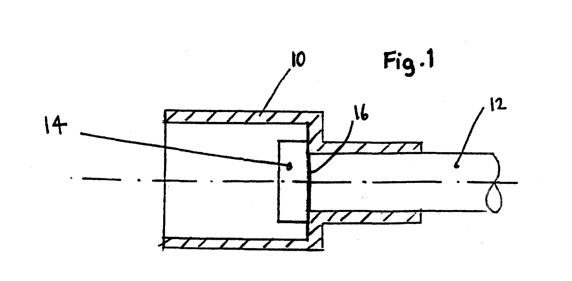
- a fibre optic termination comprises a socket 10 which is crimped to a fibre optic member 12 so that the socket 10 can co-operate with a pin (not shown) so as to join the fibre optic 12 in optical communication with a further fibre optic (not shown).
- the socket 10 defines radially opposed apertures in the form of windows 14.
- the windows 14 allow substantially radial access to an end face 16 of the fibre optic 12 so that the end face 16 can be treated in order to assist with optical alignment with the further fibre optic.
- the end face 16 may be treated by an end face treatment means (not shown) which may advantageously be in the form of a laser.
- a socket 100 is crimped to a fibre optic 120.
- the socket 100 is made from a material which is transparent to laser, so that a laser based end face treatment means (not shown) can be used to treat the end face 160.
- a laser based end face treatment means (not shown) can be used to treat the end face 160.
- access to the end face 160 for treatment can be achieved radially.
- the improved fibre optic termination allows end face treatment of the fibre optic after the fibre optic termination has been made. This avoids inaccuracies which might occur if the end face was treated before the termination was made and reduces axial off-set to a minimum. If the end face is treated before the termination is made, the invention allows post assembly correction of any minor inaccuracies which might be caused by the making of the terminations, e.g. through crimping.
- the improved accessibility to the end face 16, 160 also allows checking thereof after manufacture.
Landscapes
- Physics & Mathematics (AREA)
- General Physics & Mathematics (AREA)
- Optics & Photonics (AREA)
- Engineering & Computer Science (AREA)
- Plasma & Fusion (AREA)
- Optical Couplings Of Light Guides (AREA)
- Mechanical Coupling Of Light Guides (AREA)
Abstract
A fibre optic termination arrangement is disclosed in which a socket
housing (10) is crimped to a fibre optic (12). Access to an end face
(16) of the fibre optic (12) is provided, so as to allow an end face
treatment means to trim the end of the fibre optic (12) after assembly
of the termination, so as to improve alignment with an associated pin
and further fibre optic (not shown). In one embodiment of the invention,
the socket (10) is provided with windows or slots (14) in its side. In a
second embodiment of the invention, the end face treatment means
comprises a laser and the socket (100) has at least a portion which is
laser transparent so as to provide access to the end face (160) in
similar fashion to access provided in the first embodiment.
Description
- This invention relates to fibre optic terminations and in particular to an arrangement for treating the end face of a fibre optic.
- It is known to provide pin and socket connections for fibre optic cables. To meet the tolerances which are necessary for the relative positioning of the fibre optics forming the connection, it is preferable to use matched pairs of pins and sockets. To help achieve this, the end faces of the fibre optic cables forming the connection are treated by an end face treatment means.
- One arrangement for treating the end faces of fibre optic cables is disclosed in US 4,587,768 (Doyle R R). In this arrangement, the fibre optic is treated before the termination is made. This might give rise to later problems with alignment, e.g. if either or both of the fibre optics forming the connection are terminated by being crimped into their pin/socket, either or both may move slightly out of axial alignment with the mating half. It should also be noted that if the end face is treated before assembly, a later check over the end face would be advisable in case of axial misalignment but may prove difficult because of poor accessibility into the socket.
- In the case of the pin portion of a pin/socket connection, the fibre optic end face can be arranged to be relatively freely accessible after termination for end face treatment. The treatment of the fibre optic end face which is in a socket, however, may only be found to be possible with specially formed dies which are inserted into the socket.
- It is an object of this invention to provide an improved end face termination arrangement.
- Accordingly, the invention provides a fibre optic termination comprising a socket housing arranged in use to provide access to a fibre optic end face for an end face treatment means, characterised in that the access is provided through at least one radially defined aperture in the socket housing. The end face treatment means may comprise a laser.
- The invention also provides a fibre optic termination comprising a socket housing arranged in use to provide access to a fibre optic end face for an end face treatment means, wherein the end face treatment means comprises a laser and the access is provided through a substantially laser transparent portion of the socket housing.
- In either case, the fibre optic end face may be treated after the termination has been made.
- The invention will now be described with reference to the accompanying drawings, in which:
- Figure 1 is a plan view of a section through a fibre optic termination according to a first embodiment of the invention;
- Figure 2 is a side view of a section through the fibre optic termination of Figure 1; and
- Figure 3 is a section through a fibre optic termination according to a second embodiment of the invention.
-
- Referring now to Figures 1 and 2, a fibre optic termination comprises a
socket 10 which is crimped to a fibreoptic member 12 so that thesocket 10 can co-operate with a pin (not shown) so as to join the fibre optic 12 in optical communication with a further fibre optic (not shown). - The
socket 10 defines radially opposed apertures in the form ofwindows 14. Thewindows 14 allow substantially radial access to anend face 16 of the fibre optic 12 so that theend face 16 can be treated in order to assist with optical alignment with the further fibre optic. Theend face 16 may be treated by an end face treatment means (not shown) which may advantageously be in the form of a laser. - Referring now to Figure 3, in a second embodiment of the invention a
socket 100 is crimped to a fibre optic 120. Thesocket 100 is made from a material which is transparent to laser, so that a laser based end face treatment means (not shown) can be used to treat theend face 160. In similar fashion to the first embodiment, access to theend face 160 for treatment can be achieved radially. - In both embodiments it can be seen that the improved fibre optic termination allows end face treatment of the fibre optic after the fibre optic termination has been made. This avoids inaccuracies which might occur if the end face was treated before the termination was made and reduces axial off-set to a minimum. If the end face is treated before the termination is made, the invention allows post assembly correction of any minor inaccuracies which might be caused by the making of the terminations, e.g. through crimping. The improved accessibility to the
end face
Claims (4)
- A fibre optic termination comprising a socket housing (10) arranged in use to provide access to a fibre optic end face (16) for an end face treatment means, characterised in that the access is provided through at least one radially defined aperture (14) in the socket housing (10).
- A fibre optic termination according to Claim 1, the end face treatment means comprising a laser.
- A fibre optic termination comprising a socket housing (100) arranged in use to provide access to a fibre optic end face (160) for an end face treatment means, wherein the end face treatment means comprises a laser and the access is provided through a substantially laser transparent portion of the socket housing (100).
- A fibre optic termination according to any preceding claim, wherein the fibre optic end face (16; 160) is treated after the termination has been made.
Priority Applications (1)
| Application Number | Priority Date | Filing Date | Title |
|---|---|---|---|
| EP00109600A EP1152269A1 (en) | 2000-05-05 | 2000-05-05 | Fibre optic termination arrangements |
Applications Claiming Priority (1)
| Application Number | Priority Date | Filing Date | Title |
|---|---|---|---|
| EP00109600A EP1152269A1 (en) | 2000-05-05 | 2000-05-05 | Fibre optic termination arrangements |
Publications (1)
| Publication Number | Publication Date |
|---|---|
| EP1152269A1 true EP1152269A1 (en) | 2001-11-07 |
Family
ID=8168629
Family Applications (1)
| Application Number | Title | Priority Date | Filing Date |
|---|---|---|---|
| EP00109600A Withdrawn EP1152269A1 (en) | 2000-05-05 | 2000-05-05 | Fibre optic termination arrangements |
Country Status (1)
| Country | Link |
|---|---|
| EP (1) | EP1152269A1 (en) |
Citations (3)
| Publication number | Priority date | Publication date | Assignee | Title |
|---|---|---|---|---|
| US4747658A (en) * | 1983-03-14 | 1988-05-31 | International Telephone And Telegraph Corporation | Fiber optic contact |
| EP0558230A1 (en) * | 1992-02-28 | 1993-09-01 | AT&T Corp. | Microlenses for coupling optical fibers to elliptical light beams |
| US5293438A (en) * | 1991-09-21 | 1994-03-08 | Namiki Precision Jewel Co., Ltd. | Microlensed optical terminals and optical system equipped therewith, and methods for their manufacture, especially an optical coupling method and optical coupler for use therewith |
-
2000
- 2000-05-05 EP EP00109600A patent/EP1152269A1/en not_active Withdrawn
Patent Citations (3)
| Publication number | Priority date | Publication date | Assignee | Title |
|---|---|---|---|---|
| US4747658A (en) * | 1983-03-14 | 1988-05-31 | International Telephone And Telegraph Corporation | Fiber optic contact |
| US5293438A (en) * | 1991-09-21 | 1994-03-08 | Namiki Precision Jewel Co., Ltd. | Microlensed optical terminals and optical system equipped therewith, and methods for their manufacture, especially an optical coupling method and optical coupler for use therewith |
| EP0558230A1 (en) * | 1992-02-28 | 1993-09-01 | AT&T Corp. | Microlenses for coupling optical fibers to elliptical light beams |
Similar Documents
| Publication | Publication Date | Title |
|---|---|---|
| US5809192A (en) | Optical fiber connector having enhanced assembly means | |
| US4789351A (en) | Blind mating connector with snap ring insertion | |
| CN111200210B (en) | Connector | |
| US9678286B2 (en) | Optical connection assembly with improved guiding of the ferrules of optical contacts, ferule with reduced dimensions and connection method associated | |
| EP1133709A1 (en) | Fiber optic adapter, including hybrid connector system | |
| EP1172673A3 (en) | Alignment system for fiber optic connectors | |
| CN110208913A (en) | A kind of optical fiber connector of site operation | |
| KR100713430B1 (en) | Optical connector plug, manufacturing method and assembly tool | |
| JP2001525558A (en) | Optical connector system | |
| US6074235A (en) | Alignment post having an improved locking feature | |
| US20020028055A1 (en) | Optical cable adapter or connector | |
| JP3120354U (en) | Die-cast adapter | |
| KR20010006472A (en) | Contact connector system for light waveguides | |
| EP0827237A1 (en) | Low insertion force connector | |
| KR101492611B1 (en) | Field installable optical connector | |
| JP3312192B2 (en) | Optical fiber holding structure and optical connector | |
| CN1985412B (en) | Cable connector and method of assembling cables to said cable connector | |
| US20040062488A1 (en) | Fiber optic adapter sleeve | |
| US6485195B2 (en) | Ferrule and fiber optic connector housing having enlarged shoulders | |
| EP1659432A1 (en) | Optical coupling component for use in an optical communication connector and an optical connector using such optical coupling component | |
| JP7051706B2 (en) | Contact elements for optical connectors and optical connectors | |
| JPH07270646A (en) | Fiber optic connector | |
| US7351078B2 (en) | Connector arrangement | |
| JPH09510793A (en) | Plug-in optical connector and method of manufacturing plug-in optical connector | |
| US7118282B2 (en) | Receptacle-type optical connector easily adaptable to various specifications and method of producing the same |
Legal Events
| Date | Code | Title | Description |
|---|---|---|---|
| PUAI | Public reference made under article 153(3) epc to a published international application that has entered the european phase |
Free format text: ORIGINAL CODE: 0009012 |
|
| AK | Designated contracting states |
Kind code of ref document: A1 Designated state(s): AT BE CH CY DE DK ES FI FR GB GR IE IT LI LU MC NL PT SE |
|
| AX | Request for extension of the european patent |
Free format text: AL;LT;LV;MK;RO;SI |
|
| AKX | Designation fees paid | ||
| REG | Reference to a national code |
Ref country code: DE Ref legal event code: 8566 |
|
| STAA | Information on the status of an ep patent application or granted ep patent |
Free format text: STATUS: THE APPLICATION IS DEEMED TO BE WITHDRAWN |
|
| 18D | Application deemed to be withdrawn |
Effective date: 20020508 |