EP1152260A1 - Récepteur à filtres spectraux et lidar Doppler à détection directe en faisant application - Google Patents
Récepteur à filtres spectraux et lidar Doppler à détection directe en faisant application Download PDFInfo
- Publication number
- EP1152260A1 EP1152260A1 EP01401123A EP01401123A EP1152260A1 EP 1152260 A1 EP1152260 A1 EP 1152260A1 EP 01401123 A EP01401123 A EP 01401123A EP 01401123 A EP01401123 A EP 01401123A EP 1152260 A1 EP1152260 A1 EP 1152260A1
- Authority
- EP
- European Patent Office
- Prior art keywords
- filter
- polarizer
- standard
- spectrum
- filters
- Prior art date
- Legal status (The legal status is an assumption and is not a legal conclusion. Google has not performed a legal analysis and makes no representation as to the accuracy of the status listed.)
- Granted
Links
- 230000003595 spectral effect Effects 0.000 title claims abstract description 25
- 238000001514 detection method Methods 0.000 title claims description 4
- 238000001228 spectrum Methods 0.000 claims description 24
- 230000003287 optical effect Effects 0.000 claims description 8
- 230000004907 flux Effects 0.000 claims description 7
- 238000005259 measurement Methods 0.000 claims description 7
- 125000006850 spacer group Chemical group 0.000 claims description 2
- 238000011144 upstream manufacturing Methods 0.000 claims description 2
- 230000005540 biological transmission Effects 0.000 description 8
- 238000009792 diffusion process Methods 0.000 description 5
- 230000010287 polarization Effects 0.000 description 5
- 239000000463 material Substances 0.000 description 4
- 230000000694 effects Effects 0.000 description 3
- 239000002245 particle Substances 0.000 description 3
- 230000010363 phase shift Effects 0.000 description 3
- VYPSYNLAJGMNEJ-UHFFFAOYSA-N silicon dioxide Inorganic materials O=[Si]=O VYPSYNLAJGMNEJ-UHFFFAOYSA-N 0.000 description 3
- 230000008878 coupling Effects 0.000 description 2
- 238000010168 coupling process Methods 0.000 description 2
- 238000005859 coupling reaction Methods 0.000 description 2
- 238000010586 diagram Methods 0.000 description 2
- 239000003989 dielectric material Substances 0.000 description 2
- 239000011159 matrix material Substances 0.000 description 2
- 238000002310 reflectometry Methods 0.000 description 2
- 238000009825 accumulation Methods 0.000 description 1
- 239000000443 aerosol Substances 0.000 description 1
- 230000003667 anti-reflective effect Effects 0.000 description 1
- 230000002238 attenuated effect Effects 0.000 description 1
- 230000000295 complement effect Effects 0.000 description 1
- 238000002592 echocardiography Methods 0.000 description 1
- 235000021183 entrée Nutrition 0.000 description 1
- 238000000605 extraction Methods 0.000 description 1
- 230000002349 favourable effect Effects 0.000 description 1
- 239000011521 glass Substances 0.000 description 1
- 230000010070 molecular adhesion Effects 0.000 description 1
- 239000010453 quartz Substances 0.000 description 1
- 238000000926 separation method Methods 0.000 description 1
- 239000000377 silicon dioxide Substances 0.000 description 1
- 238000010183 spectrum analysis Methods 0.000 description 1
Images
Classifications
-
- G—PHYSICS
- G01—MEASURING; TESTING
- G01S—RADIO DIRECTION-FINDING; RADIO NAVIGATION; DETERMINING DISTANCE OR VELOCITY BY USE OF RADIO WAVES; LOCATING OR PRESENCE-DETECTING BY USE OF THE REFLECTION OR RERADIATION OF RADIO WAVES; ANALOGOUS ARRANGEMENTS USING OTHER WAVES
- G01S7/00—Details of systems according to groups G01S13/00, G01S15/00, G01S17/00
- G01S7/48—Details of systems according to groups G01S13/00, G01S15/00, G01S17/00 of systems according to group G01S17/00
- G01S7/483—Details of pulse systems
- G01S7/486—Receivers
- G01S7/487—Extracting wanted echo signals, e.g. pulse detection
-
- G—PHYSICS
- G01—MEASURING; TESTING
- G01S—RADIO DIRECTION-FINDING; RADIO NAVIGATION; DETERMINING DISTANCE OR VELOCITY BY USE OF RADIO WAVES; LOCATING OR PRESENCE-DETECTING BY USE OF THE REFLECTION OR RERADIATION OF RADIO WAVES; ANALOGOUS ARRANGEMENTS USING OTHER WAVES
- G01S17/00—Systems using the reflection or reradiation of electromagnetic waves other than radio waves, e.g. lidar systems
- G01S17/02—Systems using the reflection of electromagnetic waves other than radio waves
- G01S17/50—Systems of measurement based on relative movement of target
- G01S17/58—Velocity or trajectory determination systems; Sense-of-movement determination systems
-
- G—PHYSICS
- G01—MEASURING; TESTING
- G01S—RADIO DIRECTION-FINDING; RADIO NAVIGATION; DETERMINING DISTANCE OR VELOCITY BY USE OF RADIO WAVES; LOCATING OR PRESENCE-DETECTING BY USE OF THE REFLECTION OR RERADIATION OF RADIO WAVES; ANALOGOUS ARRANGEMENTS USING OTHER WAVES
- G01S17/00—Systems using the reflection or reradiation of electromagnetic waves other than radio waves, e.g. lidar systems
- G01S17/88—Lidar systems specially adapted for specific applications
- G01S17/95—Lidar systems specially adapted for specific applications for meteorological use
-
- G—PHYSICS
- G01—MEASURING; TESTING
- G01S—RADIO DIRECTION-FINDING; RADIO NAVIGATION; DETERMINING DISTANCE OR VELOCITY BY USE OF RADIO WAVES; LOCATING OR PRESENCE-DETECTING BY USE OF THE REFLECTION OR RERADIATION OF RADIO WAVES; ANALOGOUS ARRANGEMENTS USING OTHER WAVES
- G01S7/00—Details of systems according to groups G01S13/00, G01S15/00, G01S17/00
- G01S7/48—Details of systems according to groups G01S13/00, G01S15/00, G01S17/00 of systems according to group G01S17/00
- G01S7/481—Constructional features, e.g. arrangements of optical elements
- G01S7/4816—Constructional features, e.g. arrangements of optical elements of receivers alone
-
- G—PHYSICS
- G01—MEASURING; TESTING
- G01S—RADIO DIRECTION-FINDING; RADIO NAVIGATION; DETERMINING DISTANCE OR VELOCITY BY USE OF RADIO WAVES; LOCATING OR PRESENCE-DETECTING BY USE OF THE REFLECTION OR RERADIATION OF RADIO WAVES; ANALOGOUS ARRANGEMENTS USING OTHER WAVES
- G01S7/00—Details of systems according to groups G01S13/00, G01S15/00, G01S17/00
- G01S7/48—Details of systems according to groups G01S13/00, G01S15/00, G01S17/00 of systems according to group G01S17/00
- G01S7/483—Details of pulse systems
- G01S7/486—Receivers
-
- Y—GENERAL TAGGING OF NEW TECHNOLOGICAL DEVELOPMENTS; GENERAL TAGGING OF CROSS-SECTIONAL TECHNOLOGIES SPANNING OVER SEVERAL SECTIONS OF THE IPC; TECHNICAL SUBJECTS COVERED BY FORMER USPC CROSS-REFERENCE ART COLLECTIONS [XRACs] AND DIGESTS
- Y02—TECHNOLOGIES OR APPLICATIONS FOR MITIGATION OR ADAPTATION AGAINST CLIMATE CHANGE
- Y02A—TECHNOLOGIES FOR ADAPTATION TO CLIMATE CHANGE
- Y02A90/00—Technologies having an indirect contribution to adaptation to climate change
- Y02A90/10—Information and communication technologies [ICT] supporting adaptation to climate change, e.g. for weather forecasting or climate simulation
Definitions
- the present invention relates to a spectral receiver allowing extract a narrow bandwidth from a light flux. It can be used in any optical instrument in which one wishes to extract, from a light beam input, at least two fine spectral lines, and if necessary have also of an output beam containing the residual band. She finds a particularly important, although not exclusive, application in distance measuring devices by reflection of short light pulses, so-called “lidars", and in particular in Doppler lidars - also performing a speed measurement - so-called inconsistent or direct detection.
- the present invention aims in particular to provide a receiver allowing simultaneously and at the same time an extraction spectral separation of at least two very narrow bandwidths and optimal use of light flux entry available.
- a reflector such as a mirror will be placed on the path of the said fraction upstream of the second standard filter so that the two filters can be placed parallel to each other.
- Each standard filter will generally be a Fabry-Pérot reflection filter multiple, in a material chosen so as to be transparent for the light of the input beam to be analyzed. High selectivity will be obtained by planning sufficiently numerous reflections, generally several tens.
- the the polarizer will advantageously be replaced by a blade used under a Brewster incidence, which transmits the polarization parallel to the plane of incidence and reflects the orthogonal polarization.
- Such a receiver has very favorable characteristics.
- the resolution spectral and optical performance of such a receiver are very high. Groups bandwidths extracted can be as fine as necessary, up to a few tens of MHz or even more.
- Each standard is generally used in normal incidence. Tolerance for alignment errors is high (typically several tens of ⁇ rad), even at high resolution.
- the field of view is also important when the standard is used in incidence normal. There is simultaneous time access to both channels, which allows access almost simultaneous time on both channels if desired.
- the receiver can in particular be incorporated into a Doppler lidar which further includes means for determining the Doppler shift from of the reflection of a brief monochromatic light pulse on a target mobile.
- a Doppler lidar which further includes means for determining the Doppler shift from of the reflection of a brief monochromatic light pulse on a target mobile.
- the invention finds a very particular interest in the lidars used to measure the spectral shift with high resolution light pulses reflected or scattered by the atmosphere, clouds or the surface of the ground and coming from a laser on the ground or mounted on an aircraft or a satellite.
- the invention therefore also aims to provide an atmospheric lidar which used to determine the altitude of the atmospheric layer, clouds or ground from time-of-flight measurements of the pulses reflected on atmospheric particles and their speed, and this by determining the frequency center of the backscattered signal - and therefore its offset from frequency resignation.
- it aims to take into account the simultaneous presence of two components, of different origins, of the spectrum backscattered by the atmosphere.
- the document FR-A-2 735 935 describes a lidar with a Fizeau interferometer which allows obtain a high signal-to-noise ratio by accumulating the results obtained during numerous successive laser shots, for a narrow spectral band. Accumulation makes it possible to measure very small Doppler shifts (by example 5 MHz for a speed of 1 m / s and a wavelength of 0.35 ⁇ m) due to the movement of particles.
- the spectrum backscattered by the atmosphere has two spectral components.
- the first component is of equal spectral width or similar to that of the laser (approximately 25 to 50 MHz) and comes from the diffusion on aerosol type particles.
- a direct detection Doppler lidar for measuring the frequency central of the backscattered signal and possibly take account of the two components of different origins in the spectrum backscattered by the atmosphere can include a pulsed light source of polarized light such that a laser, a receiver of the above kind, arranged to receive echoes of light pulses emitted by the source and, on each output path of the receiver, a detector allowing spectral analysis of the beam corresponding.
- Each detector can be a matrix device with coupling of charges or CCD thus receiving spectral components selected by filters and whose respective intensity provides an indication of the offset frequency relative to the median frequency between the centers of the bands of standard filters.
- Finding the center of the line and the spectral difference due to the Doppler effect is facilitated in the case of a receiver with two standard filters by tuning the two filters so that their bandwidths are placed symmetrically on the wings of the backscattered line in the absence of Doppler shift, by detecting the two filter output streams and calculating the ratio between the difference of flow and their sum.
- the standard filters are advantageously tuned so that the ratio between the difference of flows and their sum is the same for the Mie and Rayleigh spectrum.
- the invention thus takes advantage of the fact that the receiver presents only losses very weak. In other words, it offers a wind lidar with a receiver of the above type and means for determining the offset Doppler by calculating the ratio between the difference and the sum of the flows.
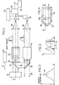
- the lidar represented in FIG. 1 comprises a source 10 of pulses short, bright lights linearly polarized in the direction shown by an arrow f and, on a return path of the backscattered light flux, a afocal optics such as a telescope followed by a spectral receiver 14 in two standard filters 16a and 16b of the same constitution. Only that of analyzer 6a is shown.
- the source 10 is generally constituted by a laser emitting very short monochromatic pulses (20 to 30 ns in general) in the visible or in the ultraviolet.
- a laser emitting very short monochromatic pulses (20 to 30 ns in general) in the visible or in the ultraviolet.
- the backscattered reflected beam is received on a polarizer 18, shown in the form of a Brewster blade oriented to allow passage to the beam entry.
- the output beam passes through a quarter-wave plate 20, which can be a thin blade of birefringent material such as quartz.
- the quarter-wave blade is followed by the first standard filter 16a.
- this filter will generally be a filter Fabry-Pérot type interference. Thirty reflections allow to obtain the spectral transmission necessary for satisfactory measurements.
- a standard filter having plates in silica and shims made of material with a low coefficient of expansion. Plates and wedges are advantageously assembled by molecular adhesion, to to obtain the mechanical stability, of about 2 nm, required in ultraviolet.
- the faces internal plates will usually be covered with thin layers dielectrics ensuring high reflectivity. We were thus able to obtain a 80% reflectivity with a distance between plates of 3 mm and an interval free spectral of 20 pm for a wavelength of 350 nm.
- the phase shift at each reflection can be made minimal, since the thin layers are usually used at normal incidence.
- the loss due to the phase shifts multiple reflections can generally be reduced to about 0.1%.
- Air-glass dioptres will generally be covered with layers anti-reflective dielectrics to improve the optical efficiency of the spectral separator.
- the filter 16a In the case of a source 10 having a wavelength of 0.35 ⁇ m, the filter 16a will generally have a maximum transmission T of around 70%, a spectral width at mid-height of about 1 pm and a loss of flux due to the phase shift by a few percent, including in polarizer 18.
- the alignment tolerances and the field of view can be 50 ⁇ rad and a few mrad respectively, normal incidence.
- the receiver thus constituted operates as follows: the beam incident is linearly polarized by the polarizer 18.
- the quarter-wave plate 20 gives the beam a circular polarization.
- the beam reflected by the filter standard 16a crosses back the slide 20 and becomes linearly polarized again, with a polarization orthogonal to the initial polarization. It is then reflected by the polarizer 18.
- This reflected beam is not attenuated, relative to the input beam, only losses, which are minimal, and the narrow band transmitted by the filter 16a. It is received by a mirror 22 which directs it towards the standard filter 6b placed parallel to filter 16a and functioning as filter 16a, but to extract a different band.
- a quarter wave plate 24 is interposed between the mirror 22 formed by a polarizer and the filter 16b. It is then possible to collect an output flow 26 corresponding to the input flow minus the gaps filters created by the filters, either for another use or to treat the component obtained by Rayleigh scattering, in a much larger band wide as the component due to Mie diffusion (as stated in the request FR 99 00566 which can be referred to) if the bandwidths of the filters standards are optimized to use Mie diffusion.
- the receiver 6a is followed by a relay optic 18 which focuses the beam received on a detector.
- each beam of output is focused by a lens 28 on the image area of a matrix sensor to charge coupling or CCD 32.
- This image area has P lines and N columns of photosensitive sites.
- a sequencer 30 defines, on each transmission of a pulse by the source 10, an observation period during which the CCD 32 measures and stores the received optical signal and a reading period.
- the signals read by a circuit 34 are processed by a processing circuit 36 which calculates the difference of flows and their sum and determines the ratio.
- a single CCD sensor is used, either alternately or with assignment of certain columns to one channel and of the other columns to I other way.
- an interference filter 16 distributes spectrally the light received towards different columns of the image area.
- the material constitution of the receiver can be that shown schematically on the Figure 5, which guarantees high spectral stability of the two filters and avoids measurement bias.
- the receiver is integrated into a single optical component.
- the polarizer 18 and the quarter wave plate 20 are fixed on a double standard of large width sharing the same layers and the same spacers including one fraction is the first filter and another fraction is the second filtered.
- a thin layer 40 balances the filters.
- the mirror 22 is fixed symmetrically to the polarizer.
- the spacing E of the transmission peaks T of the standard filters is substantially equal to the width halfway up this spectrum, as shown in Figure 3 where the effect of the shift on the intensities transmitted.
- a compromise to take account of two spectra will lead to tighten the transmission peaks relative to the Rayleigh spectrum to analyze the wings of the Rayleigh spectrum and the variation of transmission of the Mie spectrum, as shown in Figure 4.
Landscapes
- Engineering & Computer Science (AREA)
- Physics & Mathematics (AREA)
- Computer Networks & Wireless Communication (AREA)
- General Physics & Mathematics (AREA)
- Radar, Positioning & Navigation (AREA)
- Remote Sensing (AREA)
- Electromagnetism (AREA)
- Optical Radar Systems And Details Thereof (AREA)
- Radar Systems Or Details Thereof (AREA)
Abstract
Description
- ayant successivement, dans la direction de propagation d'un faisceau de lumière d'entrée, un polariseur incliné sur la dite direction, une lame quart d'onde, et un premier filtre étalon à cavité accordée livrant passage à une bande spatiale étroite et réfléchissant la fraction du spectre du faisceau située hors de la bande passante vers la lame quart d'onde et le polariseur et
- ayant, sur le trajet de la dite fraction du spectre, après réflexion sur le polariseur, un second filtre étalon à cavité accordée livrant passage à une autre bande spectrale étroite.
- la figure 1 est un schéma synoptique d'un lidar incorporant un mode particulier de mise en oeuvre de l'invention ;
- la figure 2 est un schéma montrant la disposition relative du spectre Mie et du spectre Rayleigh pour une raie dans l'ultra violet ;
- la figure 3 montre une disposition possible les courbes de transmission des filtres d'un séparateur conforme à un mode de mise en oeuvre de l'invention, par rapport à un spectre de diffusion Rayleigh ;
- la figure 4 montre un montage possible des étalons, intégrés dans un seul composant.
Claims (10)
- Récepteur à filtres étalons ayant successivement, dans la direction de propagation d'un faisceau de lumière d'entrée, un polariseur (18) incliné sur la dite direction, une lame quart d'onde (12), et un premier filtre étalon (16a) à cavité accordée livrant passage à une bande spatiale étroite et réfléchissant la fraction du spectre du faisceau hors de la bande vers la lame quart d'onde et le polariseur et ayant, sur le trajet de la dite fraction du spectre, qui est réfléchie par le polariseur (18), un second filtre étalon (16b) à cavité accordée livrant passage à une autre bande spectrale étroite.
- Récepteur selon la revendication 1, caractérisé en ce que chaque filtre étalon est un filtre Fabry-Pérot à réflexions multiples, placé sous incidence normale.
- Récepteur selon la revendication 1 ou 2, caractérisé en ce que le polariseur (18) est une lame de Brewster.
- Récepteur selon la revendication 1, 2 ou 3, caractérisé en ce qu'il est intégré dans un seul composant optique, le polariseur (18) et la lame quart d'onde (20) étant fixées sur un double étalon de grande largeur partageant les mêmes couches et les mêmes intercalaires, dont une fraction constitue le premier filtre et une autre fraction constitue le second filtre.
- Récepteur selon l'une quelconque des revendications précédentes, caractérisé par un miroir (22) placé en amont du second filtre étalon (6b) placé parallèlement au premier filtre (16a).
- Récepteur selon la revendication 5, caractérisé en ce qu' une lame quart d'onde (24) est interposée entre le miroir (22) formé par un polariseur et le second filtre.
- Lidar Doppler comprenant un récepteur suivant l'une quelconque des revendications précédentes d'extraction de deux bandes passantes étroites d'un faisceau de lumière polarisé, décalées l'une par rapport à l'autre, et comprenant des moyens de détermination du décalage Doppler du faisceau à partir de la mesure de l'intensité des bandes spectrales à la sortie des deux filtres.
- Lidar Doppler à détection directe suivant la revendication 7, pour mesurer simultanément deux composantes d'origines différentes du spectre rétrodiffusé par l'atmosphère, comme le spectre de Mie et le spectre de Rayleigh, comportant de plus une source lumineuse impulsionnelle (10), dont les deux filtres étalons sont accordés de façon que leurs bandes passantes se placent symétriquement sur les ailes de la raie rétrodiffusée en l'absence de décalage Doppler.
- Lidar Doppler selon la revendication 8, caractérisé par des moyens prévus pour mesurer les flux de sortie des deux filtres et calculer le rapport entre la différence des flux et leur somme.
- Lidar Doppler selon la revendication 7 ou 8, caractérisé en ce que les deux filtres étalons sont accordés de façon que le rapport entre la différence des flux et leur somme soit le même pour le spectre de Mie et de Rayleigh.
Applications Claiming Priority (2)
| Application Number | Priority Date | Filing Date | Title |
|---|---|---|---|
| FR0005578 | 2000-05-02 | ||
| FR0005578A FR2808595B1 (fr) | 2000-05-02 | 2000-05-02 | Recepteur a filtres speciaux et lidar doppler a detection directe en faisant application |
Publications (2)
| Publication Number | Publication Date |
|---|---|
| EP1152260A1 true EP1152260A1 (fr) | 2001-11-07 |
| EP1152260B1 EP1152260B1 (fr) | 2005-12-21 |
Family
ID=8849794
Family Applications (1)
| Application Number | Title | Priority Date | Filing Date |
|---|---|---|---|
| EP01401123A Expired - Lifetime EP1152260B1 (fr) | 2000-05-02 | 2001-04-30 | Récepteur à filtres spectraux et lidar Doppler à détection directe en faisant application |
Country Status (4)
| Country | Link |
|---|---|
| EP (1) | EP1152260B1 (fr) |
| DE (1) | DE60115986T2 (fr) |
| FR (1) | FR2808595B1 (fr) |
| NO (1) | NO321213B1 (fr) |
Cited By (5)
| Publication number | Priority date | Publication date | Assignee | Title |
|---|---|---|---|---|
| US8427649B2 (en) | 2009-05-15 | 2013-04-23 | Michigan Aerospace Corporation | Range imaging lidar |
| US8797550B2 (en) | 2009-04-21 | 2014-08-05 | Michigan Aerospace Corporation | Atmospheric measurement system |
| CN105974432A (zh) * | 2016-04-28 | 2016-09-28 | 中国科学技术大学 | 基于Fabry-Perot标准具的太阳辐射背景噪声抑制系统 |
| US10598769B2 (en) | 2013-05-06 | 2020-03-24 | Danmarks Tekniske Universitet | Coaxial direct-detection LIDAR-system |
| US11194024B2 (en) | 2017-07-12 | 2021-12-07 | Airbus Defence and Space GmbH | LIDAR arrangement and LIDAR method |
Families Citing this family (1)
| Publication number | Priority date | Publication date | Assignee | Title |
|---|---|---|---|---|
| DE102015122201A1 (de) * | 2015-12-18 | 2017-06-22 | Leibniz-Institut Für Atmosphärenphysik E.V. An Der Universität Rostock | Verfahren und Vorrichtung zur Bestimmung der Windgeschwindigkeit |
Citations (1)
| Publication number | Priority date | Publication date | Assignee | Title |
|---|---|---|---|---|
| US5216477A (en) * | 1991-05-20 | 1993-06-01 | Korb Charles L | Edge technique for measurement of laser frequency shifts including the doppler shift |
-
2000
- 2000-05-02 FR FR0005578A patent/FR2808595B1/fr not_active Expired - Lifetime
-
2001
- 2001-04-30 DE DE60115986T patent/DE60115986T2/de not_active Expired - Lifetime
- 2001-04-30 NO NO20012148A patent/NO321213B1/no not_active IP Right Cessation
- 2001-04-30 EP EP01401123A patent/EP1152260B1/fr not_active Expired - Lifetime
Patent Citations (1)
| Publication number | Priority date | Publication date | Assignee | Title |
|---|---|---|---|---|
| US5216477A (en) * | 1991-05-20 | 1993-06-01 | Korb Charles L | Edge technique for measurement of laser frequency shifts including the doppler shift |
Non-Patent Citations (2)
| Title |
|---|
| ELORANTA E W ET AL: "Modification of the High Spectral Resolution Lidar for the measurement of multiply scattered lidar returns", CONFERENCE PROCEEDINGS. SECOND TOPICAL SYMPOSIUM ON COMBINED OPTICAL-MICROWAVE EARTH AND ATMOSPHERE SENSING (CAT. NO.95TH8015), CONFERENCE PROCEEDINGS SECOND TOPICAL SYMPOSIUM ON COMBINED OPTICAL-MICROWAVE EARTH AND ATMOSPHERE SENSING, ATLANTA, GA, U, 1995, New York, NY, USA, IEEE, USA, pages 204, XP002157459, ISBN: 0-7803-2402-1 * |
| GRUND C J ET AL: "UNIVERSITY OF WISCONSIN HIGH SPECTRAL RESOLUTION LIDAR", OPTICAL ENGINEERING,US,SOC. OF PHOTO-OPTICAL INSTRUMENTATION ENGINEERS. BELLINGHAM, vol. 30, no. 1, 1991, pages 6 - 12, XP000173780, ISSN: 0091-3286 * |
Cited By (6)
| Publication number | Priority date | Publication date | Assignee | Title |
|---|---|---|---|---|
| US8797550B2 (en) | 2009-04-21 | 2014-08-05 | Michigan Aerospace Corporation | Atmospheric measurement system |
| US8427649B2 (en) | 2009-05-15 | 2013-04-23 | Michigan Aerospace Corporation | Range imaging lidar |
| US10598769B2 (en) | 2013-05-06 | 2020-03-24 | Danmarks Tekniske Universitet | Coaxial direct-detection LIDAR-system |
| CN105974432A (zh) * | 2016-04-28 | 2016-09-28 | 中国科学技术大学 | 基于Fabry-Perot标准具的太阳辐射背景噪声抑制系统 |
| CN105974432B (zh) * | 2016-04-28 | 2018-09-07 | 中国科学技术大学 | 基于Fabry-Perot标准具的太阳辐射背景噪声抑制系统 |
| US11194024B2 (en) | 2017-07-12 | 2021-12-07 | Airbus Defence and Space GmbH | LIDAR arrangement and LIDAR method |
Also Published As
| Publication number | Publication date |
|---|---|
| NO20012148L (no) | 2001-11-05 |
| NO321213B1 (no) | 2006-04-03 |
| NO20012148D0 (no) | 2001-04-30 |
| DE60115986D1 (de) | 2006-01-26 |
| DE60115986T2 (de) | 2006-09-07 |
| FR2808595B1 (fr) | 2002-07-19 |
| EP1152260B1 (fr) | 2005-12-21 |
| FR2808595A1 (fr) | 2001-11-09 |
Similar Documents
| Publication | Publication Date | Title |
|---|---|---|
| EP4090993B1 (fr) | Systeme d'imagerie lidar cohérent | |
| EP3765835B1 (fr) | Ellipsomètre ou scattéromètre instantané et procédé de mesure associé | |
| EP0870180B1 (fr) | Composant optique de modulation de polarisation, et son utilisation dans un polarimetre ou dans un ellipsometre | |
| EP3137881B1 (fr) | Systeme et procede de spectrometrie de decharge luminescente et de mesure in situ de la profondeur de gravure d'un echantillon | |
| EP3394560A1 (fr) | Dispositif et procede de mesure de hauteur en presence de couches minces | |
| WO2002095475A1 (fr) | Procede et dispostif de mesure par imagerie confocale a chromatisme entendu | |
| FR2761782A1 (fr) | Velocimetre et telemetre laser utilisant une detection coherente | |
| FR2774766A1 (fr) | Polarimetre et procede de mesure correspondant | |
| EP0027763A1 (fr) | Procédé et appareil de mesure de distance par interférométrie laser à deux longueurs d'ondes | |
| EP2405287B1 (fr) | Dispositif dé telédétection laser et procédé d'interférometrie | |
| FR3021111A1 (fr) | Pyrometre accordable en longueur d'onde pour la mesure par voie radiometrique de la temperature d'un corps | |
| EP2284510B1 (fr) | Interféromètre statique à champ compensé pour la spectroscopie a transformée de fourier | |
| EP1152260B1 (fr) | Récepteur à filtres spectraux et lidar Doppler à détection directe en faisant application | |
| EP0942261B1 (fr) | Procédé et dispositif pour la mesure de fonds de cratères sur la surface d'un échantillon | |
| EP0645645B1 (fr) | Sonde vélocimétrique et clinométrique à laser | |
| FR2929402A1 (fr) | Spectrometre compact a echantillonage bidimensionnel. | |
| FR3076347A1 (fr) | Instrument d'observation comportant un dispositif interferometrique statique a sauts de differences de marche | |
| EP4163674B1 (fr) | Système imageur lidar à détection hétérodyne de type fmcw à encombrement réduit | |
| FR2788605A1 (fr) | Separateur spectral et lidar doppler a detection directe en faisant application | |
| EP3977158B1 (fr) | Systeme lidar comprenant un element diffractif interferentiel et procede d'imagerie lidar | |
| FR3112605A1 (fr) | Dispositif de caractérisation polarimétrique de l’anisotropie d’un milieu, et système d’imagerie correspondant | |
| EP4078217B1 (fr) | Systeme lidar comprenant deux composants diffractifs | |
| EP2309236A1 (fr) | Téléscope concentrateur de champ destiné à des missions de sondage atmosphérique | |
| Liu et al. | System optimization of a field-widened Michelson interferometric spectral filter for high spectral resolution lidar | |
| FR3167720A1 (fr) | Dispositif d’étalonnage pour vélocimètre laser |
Legal Events
| Date | Code | Title | Description |
|---|---|---|---|
| PUAI | Public reference made under article 153(3) epc to a published international application that has entered the european phase |
Free format text: ORIGINAL CODE: 0009012 |
|
| AK | Designated contracting states |
Kind code of ref document: A1 Designated state(s): AT BE CH CY DE DK ES FI FR GB GR IE IT LI LU MC NL PT SE TR Kind code of ref document: A1 Designated state(s): CH DE GB IT LI |
|
| AX | Request for extension of the european patent |
Free format text: AL;LT;LV;MK;RO;SI |
|
| 17P | Request for examination filed |
Effective date: 20020321 |
|
| AKX | Designation fees paid |
Free format text: CH DE GB IT LI |
|
| RAP1 | Party data changed (applicant data changed or rights of an application transferred) |
Owner name: EADS ASTRIUM SAS |
|
| GRAP | Despatch of communication of intention to grant a patent |
Free format text: ORIGINAL CODE: EPIDOSNIGR1 |
|
| GRAS | Grant fee paid |
Free format text: ORIGINAL CODE: EPIDOSNIGR3 |
|
| GRAA | (expected) grant |
Free format text: ORIGINAL CODE: 0009210 |
|
| RAP1 | Party data changed (applicant data changed or rights of an application transferred) |
Owner name: EADS ASTRIUM SAS |
|
| AK | Designated contracting states |
Kind code of ref document: B1 Designated state(s): CH DE GB IT LI |
|
| REG | Reference to a national code |
Ref country code: GB Ref legal event code: FG4D Free format text: NOT ENGLISH |
|
| REG | Reference to a national code |
Ref country code: CH Ref legal event code: EP |
|
| REF | Corresponds to: |
Ref document number: 60115986 Country of ref document: DE Date of ref document: 20060126 Kind code of ref document: P |
|
| REG | Reference to a national code |
Ref country code: CH Ref legal event code: NV Representative=s name: ISLER & PEDRAZZINI AG |
|
| GBT | Gb: translation of ep patent filed (gb section 77(6)(a)/1977) |
Effective date: 20060322 |
|
| PLBE | No opposition filed within time limit |
Free format text: ORIGINAL CODE: 0009261 |
|
| STAA | Information on the status of an ep patent application or granted ep patent |
Free format text: STATUS: NO OPPOSITION FILED WITHIN TIME LIMIT |
|
| 26N | No opposition filed |
Effective date: 20060922 |
|
| REG | Reference to a national code |
Ref country code: CH Ref legal event code: PCAR Free format text: ISLER & PEDRAZZINI AG;POSTFACH 1772;8027 ZUERICH (CH) |
|
| PGFP | Annual fee paid to national office [announced via postgrant information from national office to epo] |
Ref country code: DE Payment date: 20200408 Year of fee payment: 20 Ref country code: CH Payment date: 20200424 Year of fee payment: 20 |
|
| PGFP | Annual fee paid to national office [announced via postgrant information from national office to epo] |
Ref country code: GB Payment date: 20200427 Year of fee payment: 20 Ref country code: IT Payment date: 20200410 Year of fee payment: 20 |
|
| REG | Reference to a national code |
Ref country code: DE Ref legal event code: R071 Ref document number: 60115986 Country of ref document: DE |
|
| REG | Reference to a national code |
Ref country code: CH Ref legal event code: PL |
|
| REG | Reference to a national code |
Ref country code: GB Ref legal event code: PE20 Expiry date: 20210429 |
|
| PG25 | Lapsed in a contracting state [announced via postgrant information from national office to epo] |
Ref country code: GB Free format text: LAPSE BECAUSE OF EXPIRATION OF PROTECTION Effective date: 20210429 |