EP1152215A1 - Angular speed sensor - Google Patents
Angular speed sensor Download PDFInfo
- Publication number
- EP1152215A1 EP1152215A1 EP00981722A EP00981722A EP1152215A1 EP 1152215 A1 EP1152215 A1 EP 1152215A1 EP 00981722 A EP00981722 A EP 00981722A EP 00981722 A EP00981722 A EP 00981722A EP 1152215 A1 EP1152215 A1 EP 1152215A1
- Authority
- EP
- European Patent Office
- Prior art keywords
- electrodes
- arms
- electrode
- oscillator
- arm
- Prior art date
- Legal status (The legal status is an assumption and is not a legal conclusion. Google has not performed a legal analysis and makes no representation as to the accuracy of the status listed.)
- Withdrawn
Links
Images


Classifications
-
- G—PHYSICS
- G01—MEASURING; TESTING
- G01C—MEASURING DISTANCES, LEVELS OR BEARINGS; SURVEYING; NAVIGATION; GYROSCOPIC INSTRUMENTS; PHOTOGRAMMETRY OR VIDEOGRAMMETRY
- G01C19/00—Gyroscopes; Turn-sensitive devices using vibrating masses; Turn-sensitive devices without moving masses; Measuring angular rate using gyroscopic effects
- G01C19/56—Turn-sensitive devices using vibrating masses, e.g. vibratory angular rate sensors based on Coriolis forces
- G01C19/5607—Turn-sensitive devices using vibrating masses, e.g. vibratory angular rate sensors based on Coriolis forces using vibrating tuning forks
Definitions
- the present invention relates to an angular rate sensor for an attitude controlling and navigation of mobile units including air crafts, automobiles, robots, vessels, and vehicles, for a protection from wobble of a still camera or video camera hands, and for a remote controller for remote controlling.
- a monolithic type of an angular rate sensor is known as fabricated by directly bonding two quartz counterparts as single crystalline piezoelectric materials in the direction of the crystallographic axis and the thickness which create opposite polarities of piezoelectric effect and then cutting them into a tuning-fork shape.
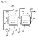
- Fig. 15 is a schematic view of the arrangement of electrodes on arms of a tuning fork oscillator in the angular rate sensor. The sensor will be described below.
- the tuning fork oscillator 100 has arms 100a and 100b.
- the tuning fork oscillator 100 also has a set of electrodes 101 to 108 provided on the arms 100a and 100b substantially throughout the whole length.
- Each electrode is formed by sputtering or vapor depositing a layer of Cr on a base material and then sputtering or vapor depositing a layer of Au, Ag, Al, or the like on the Cr layer.
- a pair of driver electrodes 101 and 102 are mounted on a first main surface and a second main surface of the arm 100a, respectively.
- a monitor electrode 106 is mounted on the second main surface of the arm 100a.
- Grounding electrodes 103, 104, and 105 are mounted on outer and inner surfaces of the arm 100a and a first main surface of the arm 100b, respectively.
- a pair of detector electrodes 107 and 108 are mounted on inner and outer surfaces of the arm 100b, respectively.
- the pair of the driver electrodes 101 and 102 mounted on the arm 100a are connected to an oscillator 109 and electrically driven by the oscillator 109.
- the amplitude of the oscillation on the tuning fork oscillator 100 developed by the oscillator circuit 109 is measured by the monitor electrode 106 mounted on the second main surface of the arm 100b.
- An angular rate input about the axis of the tuning fork oscillator 100 generates a Coriolis force in a direction vertical to the main surface of the arm 100b. The force develops a stress on the arm 100b, and then the stress is detected by the detector electrodes 107 and 108 piezoelectrically.
- a charge generated on the monitor electrode 106 is amplified by an external circuit and transferred to an automatic gain control (AGC) circuit. Then, it is compared with a reference level signal predetermined by the AGC circuit. The circuit controls the oscillator 109 in order to maintain the amplitude of the oscillation of the tuning fork oscillator 100 in constant.
- a signal from the detector electrodes 107 and 108 is amplified by an external circuit. The signal is synchronously-detected with the oscillation of the tuning fork detected by the monitor electrode 106, so that a signal with the Coriolis force modulated by the tuning fork oscillator 100 may be demodulated. Then, the signal has an undesired frequency component cut off by a low pass filter (LPF), and is output as a sensor output.
- LPF low pass filter
- the conventional angular rate sensor having the foregoing arrangement has the paired driver electrodes provided on the main surfaces of one of the arms. Thus, this makes the driving operation of the tuning fork oscillator electrically driven with a constant voltage be hardly improved.
- the present invention is developed for solving the above drawback and the object is to provide an angular rate sensor which is improved in the efficiency of the driving operation.
- an angular rate sensor includes a tuning fork oscillator having a first oscillator member of a single crystalline piezoelectric material composed of at least two arms and a base joining the two arms and a second oscillator member of the single crystalline piezoelectric material having a substantially identical shape to the first oscillator member.
- the two oscillator members are bonded directly to each other in the direction of the crystallographic axis and the thickness so that opposite polarities of a piezoelectric effect may be developed along the widthwise direction of the oscillator members.
- the tuning fork oscillator thus includes at least two arms and a base.
- the sensor further includes: first, second, third, and fourth electrodes provided on a first main surface, a second main surface, an outer surface, and an inner surface of one of the two arms of the tuning fork oscillator, respectively; a fifth electrode provided on either a first main surface or a second main surface of the other arm of the tuning fork oscillator; and sixth and seventh electrodes provided on an inner surface and an outer surface of the other arm of the tuning fork oscillator, respectively.
- a driving voltage is applied to the second and fifth electrodes at the same polarity, and applied to the first electrode at the reverse polarity against the second and fifth electrodes.
- a driving voltage is applied to the second and fifth electrodes at the opposite polarity to each other, and applied to the first electrode at the same polarity as the fifth electrode.
- the angular rate sensor has the efficiency of a driving operation improved.
- Fig. 1 is a perspective view of a tuning fork oscillator, seen from a first main surface of an angular rate sensor according to Embodiment 1 of the present invention.
- Fig. 2 is a perspective view of the tuning fork oscillator seen from a second main surface.
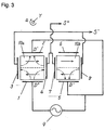
- Fig. 3 is a schematic view illustrating the positional arrangement of electrodes on arms of the angular rate sensor.
- Fig. 4 is a block diagram of an electric circuit of the angular rate sensor.
- Fig. 5 is a schematic view of the positional arrangement of electrodes on arms in an angular rate sensor according to Embodiment 2 of the present invention.
- Fig. 1 is a perspective view of a tuning fork oscillator, seen from a first main surface of an angular rate sensor according to Embodiment 1 of the present invention.
- Fig. 2 is a perspective view of the tuning fork oscillator seen from a second main surface.
- Fig. 3 is a schematic view illustrating the position
- FIG. 6 is a schematic view of the positional arrangement of electrodes on arms in an angular rate sensor according to Embodiment 3 of the present invention.
- Fig. 7 is a schematic view of the positional arrangement of electrodes on arms in an angular rate sensor according to Embodiment 4 of the present invention.
- Fig. 8 is a schematic view of the positional arrangement of electrodes on arms in an angular rate sensor according to Embodiment 5 of the present invention.
- Fig. 9 is a schematic view of the positional arrangement of electrodes on arms in an angular rate sensor according to Embodiment 6 of the present invention.
- Fig. 10 is a schematic view of the positional arrangement of electrodes on arms in an angular rate sensor according to Embodiment 7 of the present invention.
- FIG. 11 is a perspective view of a tuning fork oscillator, seen from its first main surface of an angular rate sensor according to Embodiment 8 of the present invention.
- Fig. 12 is a perspective view of the tuning fork oscillator seen from a second main surface.
- Fig. 13 is a perspective view of a modification of the same seen from a first main surface.
- Fig. 14 is a perspective view of a modification of the same seen from a second main surface.
- Fig. 15 is a schematic view illustrating the positional arrangement of electrodes on arms in a conventional angular rate sensor.
- Fig. 1 is a perspective view of a tuning fork oscillator, seen from the first main surface of an angular rate sensor according to Embodiment 1 of the present invention.
- Fig. 2 is a perspective view of the tuning fork oscillator seen from a second main surface.
- Fig. 3 is a schematic view illustrating the positional arrangement of electrodes on arms in the angular rate sensor.
- Fig. 4 is a block diagram of an electric circuit of the angular rate sensor.
- reference numerals 20a and 20b denote arms, which are oscillating portions, joined to each other at a base 20c, a fixing portion, thus forming an oscillator member 20.
- reference numerals 30a and 30b denote arms, oscillating portions, joined to each at a base 30c, a fixing portion, thus forming an oscillator member 30.
- the oscillator members 20 and 30 are made of single crystalline piezoelectric material and bonded directly to each other to have a bimorph structure thus forming a tuning fork oscillator 10.
- the tuning fork oscillator 10 thus includes arms 10a and 10b and a base 10c.
- elements to be bonded have the surfaces smoothed, hydrophilized, absorbed with hydrides, joined to each other, and heated up for removing the hydrides and hydrogen from the interface. As a result, the elements are bonded like a single structure.
- the oscillator member 20 has a crystallographic axis in the leftward direction on the figure.
- the oscillator member 30 has a crystallographic axis in the rightward direction on the figure.
- the oscillator members 20 and 30 are bonded to each other so that the crystallographic axes (along the x-axis) for generating piezoelectric forces extend in opposite directions against each other.
- reference numerals 1 through 8 denote electrodes.
- Denoted by numerals 1, 2, and 5 are driver electrodes mounted on the first and second main surfaces of the arm 10a and the first main surfaces of the arm 10b, respectively.
- the driver electrodes 1, 2, and 5 extend almost throughout the whole length of the arms 10a and 10b. They are provided by sputtering or vapor depositing a layer of Cr on a base material and then sputtering or vapor depositing a layer of Au, Ag, or Al on the layer of Cr. Electrode pads and lead-out portions of the electrodes are provided on the base 10c of the tuning fork oscillator 10.
- the lead-out portions of the electrodes on the base 10c of the tuning fork oscillator 10 is finer than the electrodes on the arms 10a and 10b of the tuning fork oscillator 10, thus they can significantly be spaced from each other. This allows the coupling capacitance between the electrodes to be minimized.
- reference numeral 6 denotes a monitor electrode 6 on the second main surface of the arm 10b.
- reference numerals 3 and 8 denote detector electrodes on outer surfaces of the arms 10a and 10b, respectively, which are connected to each other.
- Reference numerals 4 and 7 denote detector electrodes on inner surfaces of the arms 10a and 10b, respectively, which are connected to each other.
- the detector electrodes 4, 7 are linked to the electrode pad 15 through a lead-out portion 15a patterned on the first main surface of the base 10c.
- the detector electrodes 3, 8 are linked to the electrode pad 16 through a lead-out portion 16a patterned on the first main surface of the base 10c.
- the driver electrodes 1, 2, and 5 are linked to electrode pads 11, 12, and 13 and lead-out portions 11a, 12a, and 13a, respectively, patterned on the first main surface of the base 10c.
- the electrode pad 14 and lead-out portion 14a of the monitor electrode 6 are patterned on the first main surface of the base 10c.
- the lead-out portions 13a, 14a, and 16a extend from the driver electrode 2 on the second main surface to the electrode pad 13, from the monitor electrode 6 on the second main surface to the electrode pad 14, and from the detector electrodes 3 and 8 on the outer surfaces to the electrode pad 16, respectively.
- the lead-out portions are patterned on the second main surface and the outer surfaces of the base 10c then reach the first main surface.
- the positional arrangement of the electrodes in Embodiment 1 is illustrated in Fig. 3.
- a drive source 9 Between the driver electrode 1 and the driver electrode 2, 5, two alternating currents having a phase difference of 180 degrees from each other by a drive source 9.
- the arms 10a and 10b oscillate in leftward and rightward directions (along the main surfaces) in Fig. 3, respectively.
- the arrows denoted by solid line represent the crystallographic axis of quartz (electric axis).
- the arrows denoted the one-dot chain line represent the direction of an electric field.
- the alternating current signal is supplied from the drive source 9.
- the driver electrode 1 is loaded with a positive electric field
- the electrodes 2, 5 are loaded with a negative electric field at a certain time.
- the electric field is applied in the same direction as of the electric axis or polarizing direction, and thus, the left half of the arm 10a is expanded.
- the electric field is applied in a direction opposite to the electric axis or polarizing direction, hence being contracted.
- the arm 10a bows toward the inside (the right side) in Fig. 3.
- the alternating current from the drive source 9 has the polarity inverted
- the arm 10a bows toward the outside (the left side) in Fig. 3. Repeating the operation makes the arm 10a perform a resonant oscillation.
- the electric field is applied in a direction opposite to the electric axis or polarizing direction, and thus, the left half of the arm 10b is compressed.
- the electric field is applied in the same direction as of the electric axis or polarizing direction, thus being expanded.
- the arm 10b is bows toward the inside (the left side) in Fig. 3.
- the alternating current from the drive source 9 is inverted, the arm 10b bows toward the outside (the right side) in Fig. 3. Repeating the operation makes the arm 10b perform a resonant oscillation.
- the Coriolis effect deflects the arm 10a toward the lower side and the arm 10b toward the upper side in Fig. 3.
- the polarity of each charge generated on the arms is inverted, i.e., a negative charge is generated the common port S+, and a positive charge is generated in while the other common port S-.
- the angular rate is detected from the charges.
- Fig. 4 is a block diagram showing an electric circuit of the angular sensor.
- a driver circuit includes a current amplifier 40, a comparator 41, an AGC circuit 42, and an inverter 43 assembled to form a self-excited oscillator.
- the monitor electrode 6 of the tuning fork oscillator 10 develops a charge corresponding to the amplitude of an oscillation.
- the charge is received by the current amplifier circuit 40 and compared by the comparator circuit 41 with a predetermined reference level for maintaining the amplitude in constant.
- the AGC circuit 42 applies an appropriate level of sine-wave signal to the driver electrodes 2, 5 via the driver electrode 1 and the inverter 43 for attenuating the amplitude .
- the AGC circuit 42 applies a sine-wave signal to the driver electrodes 2, 5 via the driver electrode 1 and the inverter circuit 43, so that the amplitude may increases to a desired level.
- the charges having different polarities and being in proportion with the angular rate is generated by the Coriolis effect on the detector electrodes 3, 4, 7, and 8.
- the charges are received by a differential amplifier 44, phase-advanced in 90 degrees by a phase shifter 45, and synchronously-detected by a synchronous detector 46 to which an output of the current amplifier 40 in the driver circuit is supplied.
- a signal component an undesired signal component
- the electrodes for applying a driving voltage is more than that of the conventional arrangement, and the efficiency of the driving operation increases to 1.5 times.
- the driver electrode 5 and monitor electrode 6 are mounted on the first main surface and the second main surface of the arm 10b, respectively, in the embodiment. They may be switched in the location, and a signal supplied to the newly-disposed driver electrode may accordingly be inverted
- the detector electrodes 3 and 4 are mounted on the outer and inner surfaces of the arm 10a, respectively, however they may be grounding electrodes.
- a angular rate applied along the Z-axis of the arms 10a, 10b has the influence reduced or eliminated by the detector electrodes 3, 4, 7, and 8.
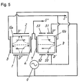
- Fig. 5 is a schematic view of the arrangement of electrodes on arms of an angular rate sensor according to Embodiment 2 of the present invention.
- like components are denoted by like numerals as those illustrated in Figs. 1, 2, 3, and 4 and will be described in no more detail but different components.
- reference numeral 50 denotes a driver electrode disposed on an outer portion of the first main surface of the arm 10b.
- Reference numeral 51 denotes a driver electrode disposed on an outer portion of the second main surface of the arm 10b.
- Reference numeral 52 denotes a monitor electrode disposed on an inner portion of the first main surface of the arm 1b.
- Reference numeral 53 denotes a monitor electrode disposed on an inner portion of the second main surface of the arm 10b.
- the electrodes for applying a driving voltage is more than that of the conventional sensor, and the efficiency of the driving operation increases to 1.7 times.
- Embodiment 2 a coupling capacitance component contained in an undesired signal component in the driving signal received by the detector electrodes is eliminated.
- the driver electrode 51 and monitor electrode 53 are mounted on the outer and inner portions of the second main surface of the arm 10b, respectively, in Embodiment 2. The locations of them may be switched over with equal effects.
- the monitor electrodes 52, 53 are mounted on the outer portion of the first main surface and the inner surface of the second main surface of the arm 10b, respectively, in Embodiment 2. Each of them may be a grounding electrode.
- Fig. 6 is a schematic view of the arrangement of electrodes on arms of an angular rate sensor according to Embodiment 3 of the present invention.
- like components are denoted by like numerals as those illustrated in Figs. 1, 2, 3, and 4 and will be described in no more detail but different components.
- reference numeral 54 denotes a driver electrode provided on a portion of the outer surface closer to the first main surface of the arm 10a.
- Reference numeral 55 denotes a driver electrode provided on a portion of the outer surface closer to the second main surface of the arm 10a.
- the electrodes for applying a driving voltage is more than that of the conventional sensor, and the intensity of electric field applied to a region of the arm 10a close to the outer surface is higher. Accordingly, the efficiency of the driving operation increases to 2.5 times.
- Embodiment 3 a coupling capacitance component contained in an undesired signal component in the driving signal received by the detector electrodes is eliminated.
- the driver electrode 5 and monitor electrode 6 are mounted on the first main surface and the second main surface of the arm 10b, respectively, in Embodiment 2. They may be switched over in the location, and the alternating currents applied to the respective driver electrodes may accordingly by opposite in the polarity to those of this arrangement.
- the monitor electrodes 54, 55 are mounted on the outer surface of the arm 10a in Embodiment 3, and the detector electrode 4 is mounted on the inner surface of the arm.
- the electrodes 54, 55 may be switched over with the detector electrode 4 in the location.
- the detector electrode 4 is mounted on the inner surface of the arm 10a in the embodiment, and however may be a grounding electrode.
- the driver electrode 5 is mounted on the first main surface of the arm 10b in the embodiment, and however may be a grounding electrode. This increases the efficiency of the driving operation to 2.0 times greater than that of the conventional sensor. Simultaneously, as the driver electrodes 1, 2 are equally spaced from the corresponding detector electrodes 7, 8, undesired coupling capacitance components generated on the detector electrode 7, 8 are offset to each other, hence an influence of a noise is eliminated.
- Fig. 7 is a schematic view of the arrangement of electrodes on arms of an angular rate sensor according to Embodiment 4 of the present invention.
- like components are denoted by like numerals as those illustrated in Fig. 6 and will be described in no more detail but different components.
- reference numeral 56 denotes a driver electrode provided on a portion of the inner surface closer to the first main surface of the arm 10a.
- Reference numeral 57 denotes a driver electrode provided on a portion of the inner surface closer to the second main surface of the arm 10a.
- the electrodes for applying a driving voltage is more than that of the conventional sensor, and the intensity of electric field applied to the arm 10a is higher than the conventional sensor. Accordingly, the efficiency of the driving operation increases to 3.2 times greater.
- Embodiment 4 a coupling capacitance component contained in an undesired signal component in the driving signal received by the detector electrodes is canceled.
- the driver electrode 5 and monitor electrode 6 are mounted on the first and second main surfaces of the arm 10b, respectively, in the embodiment. They may be switched over in the location, and the alternating currents applied to the respective driver electrodes may accordingly opposite in the polarity to those of this arrangement.
- the driver electrode 5 mounted on the first main surface of the arm 10b may be a grounding electrode. This increases the efficiency of the driving operation to 2.7 times greater than that of the conventional sensor. Simultaneously, as the driver electrodes 1, 2 are equally spaced from the corresponding detector electrodes 7, 8, undesired coupling capacitance components developed on the detector electrode 7, 8 is offset to each other, hence an influence of a noise is eliminated.
- Fig. 8 is a schematic view of the arrangement of electrodes on arms of an angular rate sensor according to Embodiment 5 of the present invention.
- like components are denoted by like numerals as those illustrated in Fig. 6 and will be described in no more detail but different components.
- reference numeral 58 denotes a driver electrode provided on a portion of the first main surface closer to the outer surface of the arm 10a.
- Reference numeral 59 denotes a driver electrode provided on a portion of the second main surface closer to the outer surface of the arm 10a.
- Reference numeral 60 denotes a monitor electrode provided on a portion of the first main surface closer to the inner surface of the arm 10a.
- Reference numeral,61 denotes a monitor electrode provided on a portion of the second main surface closer to the inner surface of the arm 10a.
- Reference numeral 62 denotes a driver electrode provided on a portion of the outer surface closer to the first main surface of the arm 10b.
- Reference numeral 63 denotes a driver electrode provided on a portion of the outer surface closer to the second main surface of the arm 10b.
- the intensity of electric field at regions of the arms 10a and 10b close to the outer surface is higher than that of the conventional sensor, as shown in Fig. 8. Accordingly, the efficiency of the driving operation increases to 3.4 times greater. As the number of monitor electrodes increases, a charge to be monitored increases hence declining the ratio of a noise to the input signal received by the AGC circuit 42.
- the drivers electrodes 58, 54, 55, 59, 50, 62, 63, and 51 are fairly spaced from the detector electrodes 4, 7 on the arms 10a, 10b. An influence of an undesired coupling capacitance component to the detector electrodes 4, 7 commonly-connected is reduced. Also, even if a small intensity of the electric field is applied to the detector electrodes 4, 7 from the driver electrodes 58, 54, 55, 59, 50, 62, 63, and 51, the undesired coupling capacitance component is offset to each other.
- the driver electrodes 54, 55 are mounted on the outer surface of the arm 10a.
- the detector electrode 4 is mounted on the inner surface of the arm.
- the driver electrode 58 and monitor electrode 60 are mounted on the first main surface of the arm.
- the driver electrode 59 and monitor electrode 61 are mounted on the second main surface of the arm.
- the driver electrodes 54, 55 and detector electrode 4 may be switched over in the location, the driver electrode 58 and monitor electrode 60 may simultaneously be switched over in the location, and the driver electrode 59 and monitor electrode 61 may be simultaneously switched over in the location. In this case, an angular rate is detected with the differential signal of the detector electrodes 4 and 7.
- the driver electrodes 62, 63 are mounted on the outer surface of the arm 10b.
- the detector electrode 7 is mounted on the inner surface of the arm.
- the driver electrode 50 and monitor electrode 52 are mounted on the first main surface.
- the driver electrode 51 and monitor electrode 53 are mounted on the second main surface of the arm 10b.
- the locations of the driver electrodes 62, 63 and that of the detector electrode 7 may be switched over, the location of the driver electrode 50 and that of the monitor electrode 52 may be simultaneously switched over, and the location of the driver electrode 51 and that of the monitor electrode 53 may be simultaneously switched over. In this case, an angular rate is detected from the differential signal of the detector electrodes 4 and 7.
- the driver electrodes 54, 55 are mounted on the outer surface of the arm 10a.
- the detector electrode 4 is mounted on the inner surface of the arm.
- the driver electrode 58 and monitor electrode 60 are mounted on the first main surface of the arm.
- the driver electrode 59 and monitor electrode 61 are mounted on the second main surface of the arm.
- the driver electrodes 62, 63 are mounted on the outer surface of the arm 10b.
- the detector electrode 7 is mounted on the inner surface of the arm.
- the driver electrode 50 and monitor electrode 52 are mounted on the first main surface of the arm.
- the driver electrode 51 and monitor electrode 53 are mounted on the second main surface of the arm.
- the locations of the driver electrode 54, 55 and that of the detector electrode 4 may be switched over, the location of the driver electrode 58 and that of the monitor electrode 60 may be simultaneously switched over, the location of the driver electrode 59 and that of the monitor electrode 61 may be simultaneously switched over, and the locations of the driver electrodes 62, 63 and that of the detector electrode 7 may be simultaneously switched over, the location of the driver electrode 50 and that of the monitor electrode 52 may be simultaneously switched over, the location of the driver electrode 51 and that of the monitor electrode 53 may be simultaneously switched over.
- an angular rate is detected, similarly to Embodiment 5, with the detector electrodes 4 and 7 connected to a common port.
- the monitor electrodes 60, 61 are mounted on the first and second main surfaces of the arm 10a, respectively, while the monitor electrodes 52 and 53 are mounted on the first and second main surfaces of the other arm 10b, respectively.
- two of the monitor electrodes 52, 53, 60, and 61 are assigned as the monitor electrodes, and rest of the two may be grounding electrodes. This arrangement permits the grounding electrodes to be disposed between the driver electrode and the detector electrode, thus reducing an undesired coupling capacitance component transferred from the driver electrode to the detector electrode.
- Fig. 9 is a schematic view of the arrangement of electrodes on arms of an angular rate sensor according to Embodiment 6 of the present invention.
- like components are denoted by like numerals as those illustrated in Figs. 3 and 8 and will be described in no more detail but different components.
- the intensity of electric field at regions of the arms 10a and 10b close to the outer surface is higher than that of the conventional sensor, as shown in Fig. 9. Accordingly, the efficiency of the driving operation increases to 3.7 times greater.
- a coupling capacitance component in an undesired signal component of the signal received by the detector electrode 4 of the arm 10a is eliminated.
- the driver electrodes 50, 51, 62, and 63 are fairly spaced from the detector electrode 7 of the arm 10b, an influence of the coupling capacitance component on the detector electrode 7 is reduced. Furthermore, even when a small electric field generated by the driver electrodes 50, 51, 62, and 63 is applied to the detector electrode 7, the coupling capacitance component is canceled on the detector electrode 7.
- the driver electrodes 54 and 55 are mounted on the outer surface of the arm 10a.
- the detector electrode 4 is mounted on the inner surface of the arm.
- the driver electrode 1 is mounted on the first main surface.
- the driver electrode 2 is mounted on the second main surface of the arm.
- the locations of the driver electrodes 54, 55 and that of the detector electrode 4 may be switched over. In this case, the angular rate is detected from a differential signal of the detector electrodes 4 and 7.
- the driver electrodes 62, 63 are mounted on the outer surface of the arm 10b.
- the detector electrode 7 is mounted on the inner surface of the arm.
- the driver electrode 50 and monitor electrode 52 are mounted on the first main surface of the arm.
- the driver electrode 51 and monitor electrode 53 are mounted on the second main surface of the arm.
- the locations of the driver electrodes 62, 63 and that of the detector electrode 7 may be switched over, the location of the driver electrode 50 and that of the monitor electrode 52 may be simultaneously switched over, the location of the driver electrode 51 and that of the monitor electrode 53 may be simultaneously switched over.
- the angular rate signal is calculated from the differential signal of the detector electrodes 4 and 7.
- the driver electrodes 54 and 55 are mounted on the outer surface of the arm 10a.
- the detector electrode 4 is mounted on the inner surface of the arm.
- the driver electrode 1 is mounted on the first main surface of the arm.
- the driver electrode 2 is mounted on the second main surface of the arm.
- the driver electrodes 62 and 63 are mounted on the outer surface of the arm 10b.
- the detector electrode 7 is mounted on the inner surface of the arm 10b.
- the driver electrode 50 and monitor electrode 52 are mounted on the first surface of the arm 10b.
- the driver electrode 51 and monitor electrode 53 are mounted on the second main surface of the arm 10b.
- the locations of the driver electrode 54, 55 and that of the detector electrode 4 may be switched over, the locations of the driver electrodes 62, 63 and that of the detector electrode 7 may be simultaneously switched over, the location of the driver electrode 50 and that of the monitor electrode 52 may be simultaneously switched over, the location of the driver electrode 51 and that of the monitor electrode 53 may be simultaneously switched over.
- the angular rate is detected with the detector electrodes 4 and 7 connected to a common port, similarly to Embodiment 6.
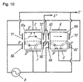
- Fig. 10 is a schematic view of the arrangement of electrodes on arms of an angular rate sensor according to Embodiment 7 of the present invention.
- like components are denoted by like numerals as those illustrated in Figs. 7 and 9 and will be described in no more detail but different components.
- reference numeral 64 denotes a driver electrode provided on a portion of the inner surface closer to the first main surface of the arm 10b.
- Reference numeral 65 denotes a detector electrode provided on a portion of the inner surface closer to the second main surface of the arm 10b.
- Reference numeral 71 denotes a detector electrode provided on a portion of the outer surface closer to the second main surface of the arm 10a.
- Reference numeral 72 denotes a detector electrode provided on a portion of the inner surface closer to the second main surface of the arm 10a.
- reference numeral 73 denotes a detector electrode provided on a portion of the outer surface closer to the second main surface of the arm 10b.
- the electrodes for applying a driving voltage are more than those of the conventional sensor, and the intensity of electric field at regions of the arms 10a and 10b close to the first main surface is higher. Accordingly, the efficiency of the driving operation increases to 3.2 times greater.
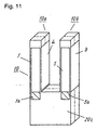
- Figs. 11, 13 and Figs. 12, 14 are perspective views of a tuning fork oscillator of an angular sensor, seen from the first and second main surfaces, respectively, according to Embodiment 8 of the present invention.
- like components are denoted by like numerals as those illustrated in Figs. 1, 2, and 3 and will be explained in no more detail but different components.
- reference numeral 1a denotes an electrode extension of the electrode 1 provided on the first main surface of an arm 10a and arranged extending into a base 20c.
- Reference numeral 5a denotes an electrode extension of the electrode 5 provided on the first main surface of a arm 10b and arranged extending into a base 20c.
- Fig. 11 denotes an electrode extension of the electrode 1 provided on the first main surface of an arm 10a and arranged extending into a base 20c.
- Reference numeral 5a denotes an electrode extension of the electrode 5 provided on the first main surface of a arm 10b and arranged extending into a base 20c.
- reference numeral 2a denotes an electrode extension of the electrode 2 provided on the second main surface of an arm 10a and arranged extending into a base 30c.
- Reference numeral 6a denotes an electrode extension of the electrode 6 provided on the second main surface of an arm 10b and arranged extending into a base 30c.
- each driver electrode of Embodiment 8 extends into the base 10c longer than that of the conventional sensor, the total area of the electrodes increases thus improving the efficiency of the driving operation.
- reference numeral 8a denotes an electrode extension of the detector electrode 8 provided on the outer surface of the arm 10b and arranged extending into the base 10c.
- Reference numeral 3a denotes an electrode extension of the detector electrode 3 provided on the outer surface of the arm 10a and arranged extending into the base 10c.
- each detector electrode of Embodiment 8 extends into the base 10c longer than that of the conventional sensor, the total area of the electrodes increases thus improving the efficiency of the detecting operation.
- the electrodes on the arms 10a and 10b described above extends into the base 10c.
- the separated electrodes on the arms such as shown in any of Embodiments 2 to 7, may extend into the base 10c.
- an angular rate sensor includes a tuning fork oscillator having a first oscillator member of a single crystalline piezoelectric material composed of at least two arms and a base joining the two arms and a second oscillator member of the single crystalline piezoelectric material having an substantially identical shape to the first oscillator member.
- the two oscillators are bonded directly to each other in the direction of the crystallographic axis and the thickness so that opposite polarities of a piezoelectric effect my be developed along the widthwise direction of the oscillators.
- the tuning fork oscillator includes at least two arms and a base.
- the sensor further includes: first, second, third, and fourth electrodes provided on a first main surface, a second main surface, an outer surface, and an inner surface of one of the two arms of the tuning fork oscillator, respectively; a fifth electrode provided on either a first main surface or a second main surface of the other arm of the tuning fork oscillator; and sixth and seventh electrodes provided on an inner surface and an outer surface of the other arm of the tuning fork oscillator, respectively.
- a driving voltage is applied to the second and fifth electrodes at the same polarity, and applied to the first electrode at the reverse polarity against the second and fifth electrodes.
- the angular rate sensor includes more electrodes to which the driving voltage is applied and has the efficiency of a driving operation improved.
Landscapes
- Physics & Mathematics (AREA)
- Engineering & Computer Science (AREA)
- General Physics & Mathematics (AREA)
- Radar, Positioning & Navigation (AREA)
- Remote Sensing (AREA)
- Gyroscopes (AREA)
Abstract
Description
Claims (32)
- An angular rate sensor comprising:a tuning fork oscillator having at least two arms and a base, including:a first oscillator member of a single crystalline piezoelectric material having at least two arms and a base joining the two arms; anda second oscillator member of the single crystalline piezoelectric material having a shape substantially identical to a shape of the first oscillator member, the first and second oscillator members being bonded directly to each other in a direction of a thickness and in a direction of a crystallographic axis so that opposite polarities of a piezoelectric effect may be developed along a widthwise direction of the first and second oscillator members;first, second, third, and fourth electrodes provided on a first main surface, a second main surface, an outer surface, and an inner surface of one of the arms of the tuning fork oscillator, respectively;a fifth electrode provided on one of first and second main surfaces of other arm of the arms of the tuning fork oscillator; andsixth and seventh electrodes provided on inner and outer surfaces of the other arm of the tuning fork oscillator, respectively,wherein, when the fifth electrode is provided on the first main surface, a driving voltage is applied to the second and fifth electrodes at a polarity identical to each other and applied to the first electrode at a polarity opposite to the second and fifth electrodes, andwherein, when the fifth electrode is provided on the second main surface, a driving voltage is applied to the second and fifth electrodes at polarities opposite to each other and applied to the first electrode at a polarity identical to the fifth electrode.
- The angular rate sensor according to claim 1,
wherein the third and seventh electrodes are connected to a common port, the fourth and sixth electrodes are connected to another common port, and a detection signal is detected from a differential signal between the common ports. - An angular rate sensor comprising:a tuning fork oscillator having at least two arms and a base, including:a first oscillator member of a single crystalline piezoelectric material having at least two arms and a base joining the two arms; anda second oscillator member of the single crystalline piezoelectric material having a shape substantially identical to a shape of the first oscillator member, the first and second oscillator members being bonded directly to each other in a direction of a thickness and in a direction of a crystallographic axis so that opposite polarities of a piezoelectric effect may be developed along a widthwise direction of the first and second oscillator members;first, second, third, and fourth electrodes provided on a first main surface, a second main surface, an outer surface, and an inner surface of one of the arms of the tuning fork oscillator, respectively;fifth and sixth electrodes provided on first and second main surfaces of other arm of the arms of the tuning fork oscillator, respectively, the fifth and sixth electrodes being provided on portions close to one of outer and inner surfaces of the other arm, respectively; anda seventh electrode provided on a surface of the other arm of the tuning fork oscillator,wherein, when the fifth and sixth electrodes are provided on the portions close to the outer surface of the other arm, respectively, the seventh electrode is provided on the outer surface,wherein, when the fifth and sixth electrodes are provided on the portions close to the inner surface of the other arm, respectively, the seventh electrode is provided on the inner surface, andwherein a driving voltage is applied to the first and sixth electrodes at a polarity identical to each other and applied to the second and fifth electrodes at an polarity opposite to the first and sixth electrodes.
- The angular rate sensor according to claim 3, further comprising an eighth electrode provided on a surface opposite to the surface of the other form arm of the fork oscillator on which the seventh electrode is provided,wherein, when the seventh electrode is provided on the outer surface, the fourth and eight electrodes are connected to a common port, the third and seventh electrodes are connected to another common port, and a detection signal is detected from a differential signal between the common ports, andwherein, when the seventh electrode is provided on the inner surface, the third and eight electrodes are connected to a common port, the fourth and seventh electrodes are connected to another common port, and a detection signal is detected from a differential signal between the common ports.
- An angular rate sensor comprising:a tuning fork oscillator having at least two arms and a base, including:a first oscillator member of a single crystalline piezoelectric material having at least two arms and a base joining the two arms; anda second oscillator member of the single crystalline piezoelectric material having a shape substantially identical to a shape of the first oscillator member, the first and second oscillator members being bonded directly to each other in a direction of a thickness and in a direction of a crystallographic axis so that opposite polarities of a piezoelectric effect may be developed along a widthwise direction of the first and second oscillator members;first, second, third, and fourth electrodes provided on a first main surface, a second main surface, an outer surface, and an inner surface of one of the arms of the tuning fork oscillator, respectively; andfifth, sixth, seventh, and eighth electrodes provided on a first main surface, a second main surface, an outer surface, and an inner surface of other arm of the arms of the tuning fork oscillator, respectively,wherein, when the fifth electrode is provided on a portion close to the outer surface of the other arm, the sixth electrode is provided on a portion close to the inner surface of the other arm,wherein, when the fifth electrode is provided on a portion close to the inner surface of the other arm, the sixth electrode is provided on a portion close to the outer surface of the other arm, andwherein a driving voltage is applied to the first and sixth electrodes at a polarity identical to each other and applied to the second and fifth electrodes at a polarity opposite to the first and sixth electrodes.
- The angular rate sensor according to claim 5, wherein a detection signal is detected from a differential signal between the third and fourth electrodes.
- An angular rate sensor comprising:wherein a driving voltage is applied to the first and fourth electrodes at a polarity identical to each other and applied to the second and third electrodes at a polarity opposite to the first and fourth electrodes.a tuning fork oscillator having at least two arms and a base, including:a first oscillator member of a single crystalline piezoelectric material having at least two arms and a base joining the two arms; anda second oscillator member of the single crystalline piezoelectric material having a shape substantially identical to a shape of the first oscillator member, the first and second oscillator members being bonded directly to each other in a direction of a thickness and in a direction of a crystallographic axis so that opposite polarities of a piezoelectric effect may be developed along a widthwise direction of the first and second oscillator members;first and second electrodes provided on first and second main surfaces of one of the arms of the tuning fork oscillator, respectively;third and fourth electrodes provided on one of outer and inner surfaces of the one of the arms, the third and fourth electrodes being provided on a portion close to the first electrode and a portion close to the second electrode, respectively; anda fifth electrode provided on a surface opposite to the surface on which the third and fourth electrodes are provided,
- The angular rate sensor according to claim 7, further comprising sixth and seventh electrodes provided on inner and outer surfaces of the other arm of the tuning fork oscillator, respectively,wherein, when the fifth electrode is provided on the inner surface of the one of the arms, a detection signal is detected from a differential signal between the sixth and seventh electrodes, or the fifth and sixth electrodes are connected to a common port, and a detection signal is detected from a differential signal between the common port and the seventh electrode, andwherein, when the fifth electrode is provided on the outer surface of the one of the arms, a detection signal is detected from a differential signal between the sixth and seventh electrodes, or the fifth and seventh electrodes are connected to a common port, and a detection signal is detected from a differential signal between the common port and the sixth electrode.
- The angular rate sensor according to claim 7, further comprising:a sixth electrode provided on one of first and second main surfaces of the other arm of the tuning fork oscillator; andseventh and eighth electrodes provided on inner and outer surfaces of the other arm, respectively,wherein, when the sixth electrode is provided on the first main surface, a driving voltage is applied to the first and sixth electrodes at polarities opposite to each other, andwherein, when the sixth electrode is provided on the second main surface, a driving voltage is applied to the first and sixth electrodes at a polarity identical to each other.
- The angular rate sensor according to claim 9,wherein, when the fifth electrode is provided on the inner surface of the one of the arms, a detection signal is detected from a differential signal between the seventh and eighth electrodes, or the fifth and seventh electrodes are connected to a common port, and a detection signal is detected from a differential signal between the common port and the eighth electrode, andwherein, when the fifth electrode is provided on the outer surface of the one of the arms, a detection signal is detected from a differential signal between the seventh and eighth electrodes, or the fifth and eight electrodes are connected to a common port, and a detection signal is detected from a differential signal between the common port and the seventh electrode.
- An angular rate sensor comprising:a tuning fork oscillator having at least two arms and a base, including:a first oscillator member of a single crystalline piezoelectric material having at least two arms and a base joining the two arms; anda second oscillator member of the single crystalline piezoelectric material having a shape substantially identical to a shape of the first oscillator member, the first and second oscillator members being bonded directly to each other in a direction of a thickness and in a direction of a crystallographic axis so that opposite polarities of a piezoelectric effect may be developed along a widthwise direction of the first and second oscillator members;first and second electrodes provided on first and second main surfaces of one of the arms of the tuning fork oscillator, respectively;third and fourth electrodes provided on an outer surface of the one of the arms, the third and fourth electrodes being provided on a portion close to the first electrode and a portion close to the second electrode, respectively; andfifth and sixth electrodes provided on an inner surface of the one of the arms, the fifth and sixth electrodes being provided on a portion close to the first electrode and a portion close to the second electrode, respectively, wherein a driving voltage is applied to the first, fourth, and sixth electrodes at a polarity identical to one another and applied to the second, third, and fifth electrodes at a polarity opposite to the first, fourth, and sixth electrodes
- The angular rate sensor according to claim 11, further comprising seventh and eighth electrodes provided on inner and outer surfaces of the other arm of the tuning fork oscillator, respectively, wherein a detection signal is detected from a differential signal between the seventh and eighth electrodes.
- The angular rate sensor according to claim 11, further comprising:a seventh electrode provided on one of first and second main surfaces of other arm of the aims of the tuning fork oscillator; andeighth and ninth electrodes provided on inner and outer surfaces of the other arm, respectively,wherein, when the seventh electrode is provided on the first main surface, a driving voltage is applied to the first and seventh electrodes at polarities opposite to each other, andwherein, when the seventh electrode is provided on the second main surface, a driving voltage is applied to the first and seventh electrodes at a polarity identical to each other.
- The angular rate sensor according to claim 13, wherein a detection signal is detected from a differential signal between the eighth and ninth electrodes.
- An angular rate sensor comprising:wherein a driving voltage is applied to the first, fourth, sixth, and seventh electrodes at a polarity identical to one another and applied to the second, third, fifth, and eighth electrodes at a polarity opposite to the first, fourth, sixth, and seventh electrodes.a tuning fork oscillator having at least two arms and a base, including:a first oscillator member of a single crystalline piezoelectric material having at least two arms and a base joining the two arms; anda second oscillator member of the single crystalline piezoelectric material having a shape substantially identical to a shape of the first oscillator member, the first and second oscillator members being bonded directly to each other in a direction of a thickness and in a direction of a crystallographic axis so that opposite polarities of a piezoelectric effect may be developed along a widthwise direction of the first and second oscillator members;first and second electrodes provided on first and second main surfaces of one of the arms of the tuning fork oscillator, respectively, the first and second electrodes being provided on portions close to an outer surface of the one of the arms, respectively;third and fourth electrodes provided on the outer surface of the one of the arms, the third and fourth electrodes being provided on a portion close to the first main surface of the one of the arms and a portion close to the second main surface of the one of the arms, respectively;fifth and sixth electrodes provided on first and second main surfaces of other arm of the arms of the tuning fork oscillator, the fifth and sixth electrodes being provided on portions close to an outer surface of the other arm of the tuning fork oscillator, respectively; andseventh and eighth electrodes provided on the outer surface of the other arm, the seventh and eighth electrodes being provided on a portion close to the first main surface of the other arm and a portion close to the second main surface of the other arm, respectively,
- The angular rate sensor according to claim 7, further comprising electrodes provided on inner surfaces of the arms of the tuning fork oscillator, respectively, wherein the electrodes being connected to a common port, and a detection signal is detected from the common port.
- An angular rate sensor comprising:wherein a driving voltage is applied to the first, fourth, sixth, and seventh electrodes at a polarity identical to one another and applied to the second, third, fifth, and eighth electrodes at a polarity opposite to the first, fourth, sixth, and seventh electrodes.a tuning fork oscillator having at least two arms and a base, including:a first oscillator member of a single crystalline piezoelectric material having at least two arms and a base joining the two arms; anda second oscillator member of the single crystalline piezoelectric material having a shape substantially identical to a shape of the first oscillator member, the first and second oscillator members being bonded directly to each other in a direction of a thickness and in a direction of a crystallographic axis so that opposite polarities of a piezoelectric effect may be developed along a widthwise direction of the first and second oscillator members;first and second electrodes provided on first and second main surfaces of one of the arms of the tuning fork oscillator, respectively, the first and second electrodes being provided on portions close to an inner surface of the one of the arms, respectively;third and fourth electrodes provided on the inner surface of the one of the arms, the third and fourth electrodes being provided on a portion close to the first main surface of the one of the arms and a portion close to the second main surface of the one of the arms, respectively;fifth and sixth electrodes provided on first and second main surfaces of other arm of the arms of the tuning fork oscillator, respectively, the fifth and sixth electrodes being provided on portions close to an inner surface of the other arm, respectively; andseventh and eighth electrodes provided on the inner surface of the other arm, the seventh and eighth electrodes being provided on a portion close to the first main surface of the other arm and a portion close to the second main surface of the other arm, respectively,
- The angular rate sensor according to claim 17, further comprising electrodes provided on outer surfaces of the arms of the tuning fork oscillator, respectively, wherein the electrodes are connected to a common port, and a detection signal is detected from the common port.
- An angular rate sensor comprising:wherein a driving voltage is applied to the first, fourth, sixth, and seventh electrodes at a polarity identical to one another and applied to the second, third, fifth, and eighth electrodes at a polarity opposite to the first, fourth, sixth, and seventh electrodes.a tuning fork oscillator having at least two arms and a base, including:a first oscillator member of a single crystalline piezoelectric material having at least two arms and a base joining the two arms; anda second oscillator member of the single crystalline piezoelectric material having a shape substantially identical to a shape of the first oscillator member, the first and second oscillator members being bonded directly to each other in a direction of a thickness and in a direction of a crystallographic axis so that opposite polarities of a piezoelectric effect may be developed along a widthwise direction of the first and second oscillator members;first and second electrodes provided on first and second main surfaces of one of the arms of the tuning fork oscillator, respectively, the first and second electrodes being provided on portions close to an outer surface of the one of the arms, respectively;third and fourth electrodes provided on the outer surface of the one of the arms, the third and fourth electrodes being provided on a portion close to the first main surface of the one of the arms and a portion close to the second main surface of the one of the arms, respectively;fifth and sixth electrodes provided on first and second main surfaces of other arm of the arms of the tuning fork oscillator, respectively, the fifth and sixth electrodes being provided on portions close to an inner surface of the other arm, respectively; andseventh and eighth electrodes provided on the inner surface of the other arm, the seventh and eighth electrodes being provided on a portion close to the first main surface of the other arm and a portion close to the second main surface of the other arm, respectively,
- The angular rate sensor according to claim 19, further comprising:a ninth electrode provided on an inner surface of the one of the arms of the tuning fork oscillator; anda tenth electrode provided on an outer surface of the other arm, wherein a detection signal is detected from a differential signal between the ninth and tenth electrodes.
- An angular rate sensor comprising:wherein a driving voltage is applied to the first, fourth, sixth, and seventh electrodes at a polarity identical to one another and applied to the second, third, fifth, and eighth electrodes at a polarity opposite to the first, fourth, sixth, and seventh electrodes.a tuning fork oscillator having at least two arms and a base, including:a first oscillator member of a single crystalline piezoelectric material having at least two arms and a base joining the two arms; anda second oscillator member of the single crystalline piezoelectric material having a shape substantially identical to a shape of the first oscillator member, the first and second oscillator members being bonded directly to each other in a direction of a thickness and in a direction of a crystallographic axis so that opposite polarities of a piezoelectric effect may be developed along a widthwise direction of the first and second oscillator members;first and second electrodes provided on first and second main surfaces of one of the arms of the tuning fork oscillator, respectively, the first and second electrodes being provided on portions close to an inner surface of the one of the arms, respectively;third and fourth electrodes provided on the inner surface of the one of the arms, the third and fourth electrodes being provided on a portion close to the first main surface of the one of the arms and a portion close to the second main surface of the one of the arms, respectively;fifth and sixth electrodes provided on first and second main surfaces of other arm of the arms of the tuning fork oscillator, respectively, the fifth and electrodes being provided on portions close to an outer surface of the other arm, respectively; andseventh and eighth electrodes provided on the outer surface of the other arm, the seventh and eighth electrodes being provided on a portion close to the first main surface of the other arm and a portion close to the second main surface of the other arm, respectively,
- The angular rate sensor according to claim 21, further comprising:a ninth electrode provided on an outer surface of the one of the arms of the tuning fork oscillator; anda tenth electrode provided on an inner surface of the other arm, wherein a detection signal is detected from a differential signal between the ninth and tenth electrodes.
- The angular rate sensor according to any of claims 15 to 22, further comprising four monitor electrodes provided on remaining portions of the first and second main surfaces of the arms of the tuning fork oscillator, respectively.
- The angular rate sensor according to any of claims 16, 18, 20, and 22, further comprising:two grounding electrodes provided on remaining portions of the first and second main surfaces of the one of the arms of the tuning fork oscillator, respectively; andtwo monitor electrodes provided on remaining portions of the first and second main surfaces of the other arm.
- An angular rate sensor comprising:wherein a driving voltage is applied to the first, fourth, seventh, and eighth electrodes at a polarity identical to one another and applied to the second, third, sixth, and ninth electrodes at a polarity opposite to the first, fourth, seventh, and eighth electrodes.a tuning fork oscillator having at least two arms and a base, including:a first oscillator member of a single crystalline piezoelectric material having at least two arms and a base joining the two arms; anda second oscillator member of the single crystalline piezoelectric material having a shape substantially identical to a shape of the first oscillator member, the first and second oscillator members being bonded directly to each other in a direction of a thickness and in a direction of a crystallographic axis so that opposite polarities of a piezoelectric effect may be developed along a widthwise direction of the first and second oscillator members;first and second electrodes provided on first and second main surfaces of one of the arms of the tuning fork oscillator, respectively;third and fourth electrodes provided on one of outer and inner surfaces of the one of the arms, the third and fourth electrodes being provided on a portion close to the first electrode and a portion close to the second electrode, respectively;a fifth electrode provided on one of the inner and outer surfaces of the one of the arms, the fifth electrodes being provided on a surface opposite to the surface on which the third and fourth electrodes are provided;sixth and seventh electrodes provided on first and second main surfaces of other arm of the arms of the tuning fork oscillator, respectively, the sixth and seventh electrodes being provided on portions close to an outer surface of the other arm, respectively; andeighth and ninth electrodes provided on the outer surface of the other arm, the eighth and ninth electrodes being provided on a portion close to the sixth electrode and a portion close to the seventh electrode, respectively,
- The angular rate sensor according to claim 25, further comprising:a tenth electrode provided on an inner surface of the other arm of the tuning fork oscillator; andtwo monitor electrodes provided on remaining portions of the first and second main surfaces of the other arm, respectively,wherein, when the fifth electrode is provided on the inner surface of the one of the arms, the fifth and tenth electrodes are connected to a common port from which a detection signal is detected, andwherein, when the fifth electrode is provided on the outer surface of the one of the arms, a detection signal is detected from a differential signal between the fifth and tenth electrodes.
- An angular rate sensor comprising:wherein a driving voltage is applied to the first, fourth, seventh, and eighth electrodes at a polarity identical to one another and applied to the second, third, sixth, and ninth electrodes at a polarity opposite to the first, fourth, seventh, and eighth electrodes.a tuning fork oscillator having at least two arms and a base, including:a first oscillator member of a single crystalline piezoelectric material having at least two arms and a base joining the two arms; anda second oscillator member of the single crystalline piezoelectric material having a shape substantially identical to a shape of the first oscillator member, the first and second oscillator members being bonded directly to each other in a direction of a thickness and in a direction of a crystallographic axis so that opposite polarities of a piezoelectric effect may be developed along a widthwise direction of the first and second oscillator members;first and second electrodes provided on first and second main surfaces of one of the arms of the tuning fork oscillator, respectively;third and fourth electrodes provided on one of outer and inner surfaces of the one of the arms, the third and fourth electrodes being provided on a portion close to the first electrode and a portion close to the second electrode, respectively;a fifth electrode provided on one of the inner and outer surfaces of the one of the arms, the fifth electrode being disposed a surface opposite to the surface on which the third and fourth electrodes are provided;sixth and seventh electrodes provided on first and second main surfaces of other arm of the arms of the tuning fork oscillator, respectively, the sixth and seventh electrodes being provided on portions close to an inner surface of the other arm, respectively; andeighth and ninth electrodes provided on the inner surface of the other arm, the eighth and ninth electrodes being provided on a portion close to the sixth electrode and a portion close to the seventh electrode, respectively,
- The angular rate sensor according to claim 27, further comprising:a tenth electrode provided on an outer surface of the other arm of the tuning fork oscillator; andtwo monitor electrodes provided on remaining portions of the first and second main surfaces of the other arm,wherein, when the fifth electrode is provided on the inner surface of the one of the arms, a detection signal is detected from a differential signal between the fifth and tenth electrodes, andwherein, when the fifth electrode is provided on the outer surface of the one of the arms, the fifth and tenth electrodes are connected to a common port from which a detection signal is detected.
- An angular rate sensor comprising:a tuning fork oscillator having at least two arms and a base, including:a first oscillator member of a single crystalline piezoelectric material having at least two arms and a base joining the two arms; anda second oscillator member of the single crystalline piezoelectric material having a shape substantially identical to a shape of the first oscillator member, the first and second oscillator members being bonded directly to each other in a direction of a thickness and in a direction of a crystallographic axis so that opposite polarities of a piezoelectric effect may be developed along a widthwise direction of the first and second oscillator members;first and second electrodes provided on first and second main surfaces of one of the arms of the tuning fork oscillator, respectively;third and fourth electrodes provided on an outer surface of the one of the arms, the third and fourth electrodes being provided on a portion close to the first electrode and a portion close to the second electrode, respectively;fifth and sixth electrodes provided on an inner surface of the one of the arms, the fifth and sixth electrodes being provided on a portion close to the first electrode and a portion close to the second electrode, respectively;a seventh electrode provided on one of first and second main surfaces of other arm of the arms of the tuning fork oscillator;eighth and ninth electrodes provided on an outer surface of the other arm, the eighth and ninth electrodes being provided on a portion close to the first main surface of the other arm and a portion close to the second main surface of the other arm, respectively; andtenth and eleventh electrodes provided on an inner surface of the other arm, the tenth and eleventh electrodes being provided on a portion close to the first main surface of the other arm and a portion close to the second main surface of the other arm, respectively,wherein, when the seventh electrode is provided on the first main surface, a driving voltage is applied to the first, eighth, and tenth electrodes at a polarity identical to one another and applied to the second, third, fifth, and seventh electrodes at a polarity opposite to the first, eighth, and tenth electrodes, andwherein, when the seventh electrode is provided on the second main surface, a driving voltage is applied to the first and seventh electrodes at a polarity identical to each other and applied to the second, third, fifth, ninth, and eleventh electrodes at a polarity opposite to the first and seventh electrodes.
- The angular rate sensor according to claim 29,wherein, when the seventh electrode is provided on the first main surface, the fourth and ninth electrodes are connected to a common port, the sixth and eleventh electrodes are connected to another common port, and a detection signal is detected from a differential signal between the common ports, andwherein, when the seventh electrode is provided on the second main surface, the fourth and eighth electrodes are connected to a common port, the sixth and tenth electrodes are connected to another common port, and a detection signal is detected from a differential signal between the common ports.
- The angular rate sensor according to any of claims 1 to 30, wherein the electrodes provided on the first and second main surfaces of the arms are extended onto a surface of the base.
- The angular rate sensor according to any of claim 1, claims 3 to 9, claims 11 to 13, and claims 15 to 29, wherein the electrodes provided on the outer surfaces of the arms are extended onto a surface of the base.
Applications Claiming Priority (3)
| Application Number | Priority Date | Filing Date | Title |
|---|---|---|---|
| JP35430499 | 1999-12-14 | ||
| JP35430499A JP4449128B2 (en) | 1999-12-14 | 1999-12-14 | Angular velocity sensor |
| PCT/JP2000/008862 WO2001044755A1 (en) | 1999-12-14 | 2000-12-14 | Angular speed sensor |
Publications (2)
| Publication Number | Publication Date |
|---|---|
| EP1152215A1 true EP1152215A1 (en) | 2001-11-07 |
| EP1152215A4 EP1152215A4 (en) | 2006-06-07 |
Family
ID=18436645
Family Applications (1)
| Application Number | Title | Priority Date | Filing Date |
|---|---|---|---|
| EP00981722A Withdrawn EP1152215A4 (en) | 1999-12-14 | 2000-12-14 | Angular speed sensor |
Country Status (4)
| Country | Link |
|---|---|
| US (1) | US6523410B2 (en) |
| EP (1) | EP1152215A4 (en) |
| JP (1) | JP4449128B2 (en) |
| WO (1) | WO2001044755A1 (en) |
Cited By (3)
| Publication number | Priority date | Publication date | Assignee | Title |
|---|---|---|---|---|
| EP1152214A4 (en) * | 1999-11-16 | 2006-06-07 | Matsushita Electric Industrial Co Ltd | ANGLE SPEED SENSOR |
| EP1314962A4 (en) * | 2000-08-30 | 2006-06-21 | Matsushita Electric Industrial Co Ltd | ANGULAR SPEED SENSOR |
| US7188525B2 (en) | 2001-10-09 | 2007-03-13 | Fujitsu Limited | Angular velocity sensor |
Families Citing this family (13)
| Publication number | Priority date | Publication date | Assignee | Title |
|---|---|---|---|---|
| JP2001208546A (en) * | 1999-11-16 | 2001-08-03 | Matsushita Electric Ind Co Ltd | Angular velocity sensor |
| JP2002122431A (en) * | 2000-10-16 | 2002-04-26 | Matsushita Electric Ind Co Ltd | Angular velocity sensor and manufacturing method thereof |
| JP2004153624A (en) * | 2002-10-31 | 2004-05-27 | Nippon Dempa Kogyo Co Ltd | Tuning fork type crystal resonator and rod resonator |
| US6941207B2 (en) * | 2003-10-10 | 2005-09-06 | Matsushita Electric Industrial Co., Ltd. | Steering angular velocity detecting device |
| JP5117506B2 (en) * | 2006-11-10 | 2013-01-16 | コーニンクレッカ フィリップス エレクトロニクス エヌ ヴィ | Oscillating element for photoacoustic detector |
| JP2008157701A (en) | 2006-12-22 | 2008-07-10 | Sony Corp | Piezoelectric element, vibration-type gyro sensor, electronic device, and method of manufacturing piezoelectric element |
| JP2008157748A (en) | 2006-12-22 | 2008-07-10 | Fujitsu Media Device Kk | Angular velocity sensor |
| JP4395171B2 (en) | 2007-02-23 | 2010-01-06 | 多摩川精機株式会社 | Angular velocity sensor and manufacturing method thereof |
| JP2009194629A (en) * | 2008-02-14 | 2009-08-27 | Seiko Instruments Inc | Method of manufacturing piezoelectric vibration piece, piezoelectric vibration piece, wafer, piezoelectric vibrator, oscillator, electronic equipment, and radio clock |
| JP4636093B2 (en) * | 2008-02-20 | 2011-02-23 | セイコーエプソン株式会社 | Vibrating piece, vibrator, oscillator, and vibrating piece manufacturing method |
| CN102725606A (en) * | 2010-01-29 | 2012-10-10 | 松下电器产业株式会社 | Angular velocity sensor |
| WO2012081294A1 (en) * | 2010-12-16 | 2012-06-21 | 株式会社村田製作所 | Tuning bar type piezoelectric vibrator and tuning fork type piezoelectric vibrator |
| JP6160027B2 (en) * | 2012-04-27 | 2017-07-12 | セイコーエプソン株式会社 | Vibrating piece and gyro sensor, electronic device and moving body |
Family Cites Families (8)
| Publication number | Priority date | Publication date | Assignee | Title |
|---|---|---|---|---|
| SE466817B (en) * | 1989-02-27 | 1992-04-06 | Bofors Ab | BEFORE GYRO PROVIDES SENSOR ELEMENTS |
| JP3399150B2 (en) * | 1995-04-28 | 2003-04-21 | 松下電器産業株式会社 | Angular velocity sensor |
| WO1997009585A1 (en) * | 1995-09-08 | 1997-03-13 | Matsushita Electric Industrial Co., Ltd. | Angular velocity sensor |
| JPH09273933A (en) * | 1996-04-04 | 1997-10-21 | Matsushita Electric Ind Co Ltd | Angular velocity sensor |
| JP3732582B2 (en) * | 1996-07-25 | 2006-01-05 | トヨタ自動車株式会社 | Angular velocity detector |
| JPH10221087A (en) * | 1996-12-06 | 1998-08-21 | Ngk Insulators Ltd | Vibrator, vibration-type gyroscope, its manufacture, method for excitation of vibrator and method for detection of vibration of vibrator |
| US5939631A (en) * | 1998-03-13 | 1999-08-17 | Bei Technologies Inc. | Low impedance single-ended tuning fork and method |
| JP3335122B2 (en) * | 1998-05-06 | 2002-10-15 | 松下電器産業株式会社 | Angular velocity sensor |
-
1999
- 1999-12-14 JP JP35430499A patent/JP4449128B2/en not_active Expired - Fee Related
-
2000
- 2000-12-14 WO PCT/JP2000/008862 patent/WO2001044755A1/en not_active Ceased
- 2000-12-14 EP EP00981722A patent/EP1152215A4/en not_active Withdrawn
- 2000-12-14 US US09/890,458 patent/US6523410B2/en not_active Expired - Fee Related
Cited By (3)
| Publication number | Priority date | Publication date | Assignee | Title |
|---|---|---|---|---|
| EP1152214A4 (en) * | 1999-11-16 | 2006-06-07 | Matsushita Electric Industrial Co Ltd | ANGLE SPEED SENSOR |
| EP1314962A4 (en) * | 2000-08-30 | 2006-06-21 | Matsushita Electric Industrial Co Ltd | ANGULAR SPEED SENSOR |
| US7188525B2 (en) | 2001-10-09 | 2007-03-13 | Fujitsu Limited | Angular velocity sensor |
Also Published As
| Publication number | Publication date |
|---|---|
| US20020134156A1 (en) | 2002-09-26 |
| JP2001165664A (en) | 2001-06-22 |
| US6523410B2 (en) | 2003-02-25 |
| JP4449128B2 (en) | 2010-04-14 |
| EP1152215A4 (en) | 2006-06-07 |
| WO2001044755A1 (en) | 2001-06-21 |
Similar Documents
| Publication | Publication Date | Title |
|---|---|---|
| US6523410B2 (en) | Angular rate sensor | |
| AU763549B2 (en) | Angular velocity sensor | |
| EP0764828B1 (en) | Angular velocity sensor | |
| EP0955519B1 (en) | Angular velocity sensor and process for manufacturing the same | |
| JPH07113645A (en) | Vibrating gyro | |
| EP1950529A1 (en) | Angular velocity sensor | |
| US6151965A (en) | Structure of angular rate sensor for minimizing output noise | |
| US6907784B2 (en) | Vibration type angular velocity sensor | |
| JP2001208546A (en) | Angular velocity sensor | |
| EP1696205A1 (en) | Tuning fork vibrator for angular velocity sensor, angular velocity sensor using the vibrator, and vehicle using the angular velocity sensor | |
| WO2005078389A1 (en) | Angular velocity sensor | |
| CA2586549A1 (en) | Oscillating micro-mechanical sensor of angular velocity | |
| US6564639B1 (en) | Angular speed sensor | |
| JP3360510B2 (en) | Angular velocity sensor | |
| JP3646759B2 (en) | Vibrating gyro | |
| JP4440360B2 (en) | Angular velocity detector | |
| JPH116738A (en) | Angular velocity sensor | |
| JP2002039760A (en) | Angular velocity sensor | |
| JPH11237403A (en) | External force detecting sensor and its offset voltage regulating method | |
| JP2000258164A (en) | Oscillation gyro | |
| JP2000292171A (en) | Vibration gyro | |
| JPH0798228A (en) | Vibrating gyro | |
| JP2003139538A (en) | Angular velocity sensor | |
| JPWO2005103619A1 (en) | Vibration gyro and method for detecting angular velocity of vibration gyro | |
| JP2000310534A (en) | Angular velocity sensor |
Legal Events
| Date | Code | Title | Description |
|---|---|---|---|
| PUAI | Public reference made under article 153(3) epc to a published international application that has entered the european phase |
Free format text: ORIGINAL CODE: 0009012 |
|
| 17P | Request for examination filed |
Effective date: 20010814 |
|
| AK | Designated contracting states |
Kind code of ref document: A1 Designated state(s): AT BE CH CY DE DK ES FI FR GB GR IE IT LI LU MC NL PT SE TR |
|
| AX | Request for extension of the european patent |
Free format text: AL;LT;LV;MK;RO;SI |
|
| RBV | Designated contracting states (corrected) |
Designated state(s): DE FR GB IT SE |
|
| A4 | Supplementary search report drawn up and despatched |
Effective date: 20060510 |
|
| 17Q | First examination report despatched |
Effective date: 20080526 |
|
| RAP1 | Party data changed (applicant data changed or rights of an application transferred) |
Owner name: PANASONIC CORPORATION |
|
| STAA | Information on the status of an ep patent application or granted ep patent |
Free format text: STATUS: THE APPLICATION IS DEEMED TO BE WITHDRAWN |
|
| 18D | Application deemed to be withdrawn |
Effective date: 20150701 |