EP1152170A1 - A position recognition arrangement - Google Patents
A position recognition arrangement Download PDFInfo
- Publication number
- EP1152170A1 EP1152170A1 EP00109599A EP00109599A EP1152170A1 EP 1152170 A1 EP1152170 A1 EP 1152170A1 EP 00109599 A EP00109599 A EP 00109599A EP 00109599 A EP00109599 A EP 00109599A EP 1152170 A1 EP1152170 A1 EP 1152170A1
- Authority
- EP
- European Patent Office
- Prior art keywords
- positions
- detection
- series
- arrangement
- position recognition
- Prior art date
- Legal status (The legal status is an assumption and is not a legal conclusion. Google has not performed a legal analysis and makes no representation as to the accuracy of the status listed.)
- Withdrawn
Links
Images
Classifications
-
- F—MECHANICAL ENGINEERING; LIGHTING; HEATING; WEAPONS; BLASTING
- F16—ENGINEERING ELEMENTS AND UNITS; GENERAL MEASURES FOR PRODUCING AND MAINTAINING EFFECTIVE FUNCTIONING OF MACHINES OR INSTALLATIONS; THERMAL INSULATION IN GENERAL
- F16H—GEARING
- F16H59/00—Control inputs to control units of change-speed- or reversing-gearings for conveying rotary motion
- F16H59/02—Selector apparatus
- F16H59/04—Ratio selector apparatus
- F16H59/044—Ratio selector apparatus consisting of electrical switches or sensors
Definitions
- This invention relates to position recognition arrangements and in particular to a position recognition arrangement which is suitable for a selector lever of a motor vehicle.
- the invention provides a position recognition arrangement for a selector means of a vehicle, said selector means having a plurality of valid selectable positions, characterised in that said position recognition arrangement comprises a plurality of substantially discreet resistances connected in series, having within said series detection positions which correspond to said valid selectable positions, and further comprising a position detection means which is arranged in use to move between said detection positions in correspondence to a selection between said valid selectable positions, whereby each said detection position presents to said detection means an unique resistance and positions in between said detection positions present substantially no change in resistance.
- Said series may be connected at one of said detection positions to an electric source and in such a manner that said detection positions comprise for said position detection means a potential divider across said series.
- Said electric source may be connected across said position detection means and a said detection position which is at one end of said series.
- Said position recognition arrangement may be arranged in use to provide to a user or to a control means a signal indicative of a selected said valid selectable position.
- Said position recognition arrangement may comprise a resistance coded switch.
- Said valid selectable positions may represent transmission ratios.
- Said recognition arrangement may comprise a gear ratio recognition means of a motor cycle transmission.
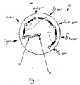
- Figure 1 is a schematic representation of part of a position recognition arrangement according to the invention.
- a motor cycle (not shown further) includes a transmission having six gear ratios selected using a gear selector in a "one-down-five-up" arrangement.
- a resistance coded switch 10 co-operates with the ratio selection lever in order to provide a signal to a control means (not shown) indicative of the selected ratio.
- the control means converts this signal into a visual indication displayed on a display means so that a user can tell which ratio has been selected or whether the neutral position has been selected.
- the switch 10 comprises seven discreet positions which correspond to the selection of first gear 1 st , neutral N, second 2 nd , third 3 rd , fourth 4 th , fifth 5 th and sixth 6 th gears.
- the switch 10 includes a wiper 12 which is moved by a shaft 14 in co-operation with a selector drum.
- the gear ratio positions are connected together in series by a series arrangement of discreet resistances 16.
- the wiper 12 and the first gear position are connected to a source of electrical potential.
- each gear position will have a unique resistance.
- the voltage dropped across the resistances making up the series for that ratio will be different for each gear position. In this manner, a discreet voltage for each position is provided and intermediate positions are not falsely detected as validly selected positions.
- This arrangement shows a saving of six lines when compared, for example, to the arrangement of US 5,748,112. While described in relation to motor cycle selector lever arrangements, it will be noted that this arrangement could be applied to other selector lever arrangements, such as that of US 5,748,112, so as to reduce the number of control lines necessary and provide protection against the inconvenience and uncertainty caused by potentially erroneous gear position indication.
Landscapes
- Engineering & Computer Science (AREA)
- General Engineering & Computer Science (AREA)
- Mechanical Engineering (AREA)
- Mechanical Control Devices (AREA)
Abstract
A position recognition arrangement (10) suitable for a selector (12, 14) in a
vehicle is disclosed. The selector lever comprises a transmission selector of, for
example, a motor cycle and has a plurality of valid selectable positions(1, N, 2, 3, 4,
5, 6). The position recognition arrangement comprises a series connected,
resistance coded switch (10).
Description
- This invention relates to position recognition arrangements and in particular to a position recognition arrangement which is suitable for a selector lever of a motor vehicle.
- It is known to provide a position recognition arrangement for a selector lever of a vehicle and one such arrangement is disclosed in US 5,748,112. In this arrangement, it is necessary to provide a separate control line for each selected position.
- It is an object of this invention to provide an improved position recognition arrangement.
- Accordingly, the invention provides a position recognition arrangement for a selector means of a vehicle, said selector means having a plurality of valid selectable positions, characterised in that said position recognition arrangement comprises a plurality of substantially discreet resistances connected in series, having within said series detection positions which correspond to said valid selectable positions, and further comprising a position detection means which is arranged in use to move between said detection positions in correspondence to a selection between said valid selectable positions, whereby each said detection position presents to said detection means an unique resistance and positions in between said detection positions present substantially no change in resistance.
- Said series may be connected at one of said detection positions to an electric source and in such a manner that said detection positions comprise for said position detection means a potential divider across said series.
- Said electric source may be connected across said position detection means and a said detection position which is at one end of said series.
- Said position recognition arrangement may be arranged in use to provide to a user or to a control means a signal indicative of a selected said valid selectable position.
- Said position recognition arrangement may comprise a resistance coded switch.
- Said valid selectable positions may represent transmission ratios. Said recognition arrangement may comprise a gear ratio recognition means of a motor cycle transmission.
- The invention will now be described by way of example only and with reference to the accompanying drawing, in which:
Figure 1 is a schematic representation of part of a position recognition arrangement according to the invention. - Referring to the figure, a motor cycle (not shown further) includes a transmission having six gear ratios selected using a gear selector in a "one-down-five-up" arrangement. A resistance coded
switch 10 co-operates with the ratio selection lever in order to provide a signal to a control means (not shown) indicative of the selected ratio. - The control means converts this signal into a visual indication displayed on a display means so that a user can tell which ratio has been selected or whether the neutral position has been selected. The
switch 10 comprises seven discreet positions which correspond to the selection of first gear 1 st , neutral N, second 2 nd , third 3 rd , fourth 4 th , fifth 5 th and sixth 6 th gears. Theswitch 10 includes awiper 12 which is moved by ashaft 14 in co-operation with a selector drum. - The gear ratio positions are connected together in series by a series arrangement of
discreet resistances 16. Thewiper 12 and the first gear position are connected to a source of electrical potential. - By series connection of the
resistances 16, each gear position will have a unique resistance. As thewiper 12 moves between the ratio positions, the voltage dropped across the resistances making up the series for that ratio will be different for each gear position. In this manner, a discreet voltage for each position is provided and intermediate positions are not falsely detected as validly selected positions. - Through the resistance coding, it can be seen that only two lines need to be provided to the gear
selection indicator switch 10 of the present invention, i.e. one to one end of the series ofresistances 16 and the other to thewiper 12. - This arrangement shows a saving of six lines when compared, for example, to the arrangement of US 5,748,112. While described in relation to motor cycle selector lever arrangements, it will be noted that this arrangement could be applied to other selector lever arrangements, such as that of US 5,748,112, so as to reduce the number of control lines necessary and provide protection against the inconvenience and uncertainty caused by potentially erroneous gear position indication.
Claims (7)
- A position recognition arrangement for a selector means of a vehicle, said selector means having a plurality of valid selectable positions, characterised in that said position recognition arrangement (10) comprises a plurality of substantially discreet resistances (16) connected in series, having within said series detection positions (1, N, 2, 3, 4, 5, 6) which correspond to said valid selectable positions and further comprising a position detection means (12) which is arranged in use to move between said detection positions (1, N, 2, 3, 4, 5, 6) in correspondence to a selection between said valid selectable positions, whereby each said detection position (1, N, 2, 3, 4, 5, 6) presents to said detection means (12) an unique resistance and positions in between said detection positions (1, N, 2, 3, 4, 5, 6) present substantially no change in resistance.
- An arrangement according to Claim 1, wherein said series is connected at one of said detection positions (1, N, 2, 3, 4, 5, 6) to an electric source and in such a manner that said detection positions (1, N, 2, 3, 4, 5, 6) comprise for said position detection means (12) a potential divider across said series.
- An arrangement according to Claim 2, wherein said electric source is connected across said position detection means (12) and a said detection position (1st gear) which is at one end of said series.
- An arrangement according any preceding claim, wherein said position recognition arrangement (12) is arranged in use to provide to a user or to a control means a signal indicative of a selected said valid selectable position.
- An arrangement according to any preceding claim, said position recognition arrangement comprising a resistance coded switch.
- An arrangement according to any preceding claim, said valid selectable positions representing transmission ratios.
- A position recognition arrangement according to any preceding claim, comprising a gear ratio recognition means of a motor cycle transmission.
Priority Applications (1)
| Application Number | Priority Date | Filing Date | Title |
|---|---|---|---|
| EP00109599A EP1152170A1 (en) | 2000-05-05 | 2000-05-05 | A position recognition arrangement |
Applications Claiming Priority (1)
| Application Number | Priority Date | Filing Date | Title |
|---|---|---|---|
| EP00109599A EP1152170A1 (en) | 2000-05-05 | 2000-05-05 | A position recognition arrangement |
Publications (1)
| Publication Number | Publication Date |
|---|---|
| EP1152170A1 true EP1152170A1 (en) | 2001-11-07 |
Family
ID=8168628
Family Applications (1)
| Application Number | Title | Priority Date | Filing Date |
|---|---|---|---|
| EP00109599A Withdrawn EP1152170A1 (en) | 2000-05-05 | 2000-05-05 | A position recognition arrangement |
Country Status (1)
| Country | Link |
|---|---|
| EP (1) | EP1152170A1 (en) |
Cited By (1)
| Publication number | Priority date | Publication date | Assignee | Title |
|---|---|---|---|---|
| CN104565339A (en) * | 2013-10-23 | 2015-04-29 | 诸城福田汽车科技开发有限公司 | Electric-control gear shifting and selecting operating device and vehicle |
Citations (6)
| Publication number | Priority date | Publication date | Assignee | Title |
|---|---|---|---|---|
| DE1964855A1 (en) * | 1969-12-24 | 1971-07-01 | Bertram Fab Ernst & Wilhelm | Electrical display device for displaying the shift position of a transmission, in particular an automatic transmission in a motor vehicle |
| US4914594A (en) * | 1987-02-12 | 1990-04-03 | Japan Automatic Transmission Co., Ltd. | Detector for detecting selector position of automatic transmission |
| DE3930897A1 (en) * | 1989-09-15 | 1991-03-28 | Vdo Schindling | CIRCUIT ARRANGEMENT FOR SELECTOR LEVER DETECTION |
| DE4339931C1 (en) * | 1993-11-24 | 1995-03-30 | Daimler Benz Ag | Locator (position sensor, position encoder), in particular for the selector lever of a vehicle gear (transmission, gearbox) |
| US5561416A (en) * | 1995-05-01 | 1996-10-01 | Ford Motor Company | Position sensing apparatus |
| US5748112A (en) | 1995-06-22 | 1998-05-05 | Bayerische Motoren Werke Aktiengesellschaft | Position recognition arrangement for a selector lever in motor vehicles |
-
2000
- 2000-05-05 EP EP00109599A patent/EP1152170A1/en not_active Withdrawn
Patent Citations (6)
| Publication number | Priority date | Publication date | Assignee | Title |
|---|---|---|---|---|
| DE1964855A1 (en) * | 1969-12-24 | 1971-07-01 | Bertram Fab Ernst & Wilhelm | Electrical display device for displaying the shift position of a transmission, in particular an automatic transmission in a motor vehicle |
| US4914594A (en) * | 1987-02-12 | 1990-04-03 | Japan Automatic Transmission Co., Ltd. | Detector for detecting selector position of automatic transmission |
| DE3930897A1 (en) * | 1989-09-15 | 1991-03-28 | Vdo Schindling | CIRCUIT ARRANGEMENT FOR SELECTOR LEVER DETECTION |
| DE4339931C1 (en) * | 1993-11-24 | 1995-03-30 | Daimler Benz Ag | Locator (position sensor, position encoder), in particular for the selector lever of a vehicle gear (transmission, gearbox) |
| US5561416A (en) * | 1995-05-01 | 1996-10-01 | Ford Motor Company | Position sensing apparatus |
| US5748112A (en) | 1995-06-22 | 1998-05-05 | Bayerische Motoren Werke Aktiengesellschaft | Position recognition arrangement for a selector lever in motor vehicles |
Cited By (1)
| Publication number | Priority date | Publication date | Assignee | Title |
|---|---|---|---|---|
| CN104565339A (en) * | 2013-10-23 | 2015-04-29 | 诸城福田汽车科技开发有限公司 | Electric-control gear shifting and selecting operating device and vehicle |
Similar Documents
| Publication | Publication Date | Title |
|---|---|---|
| EP0857333B1 (en) | Method of displaying a shift lever position for an electronically-controlled automatic transmission system | |
| EP0870267B1 (en) | Method of shifting in a manual mode of an electronically-controlled automatic transmission system | |
| US5425686A (en) | Transmission control module responsive to steering-wheel-mounted switches for changing between an auto, semi-auto and manual modes | |
| EP0540112A1 (en) | Electronic device for gear selection in an automatic transmission for motor vehicles | |
| KR890004032B1 (en) | Automotive automatic transmission | |
| KR101655624B1 (en) | Electronic SHIFT LEVER aSSEMBLY for vehicle | |
| US20030056613A1 (en) | Control device for an automatically and manually shiftable gearbox in a motor vehicle | |
| HK41597A (en) | Indication device for an automatic vehicle transmission | |
| US6018294A (en) | Automatic transmission shift indicator system | |
| EP1238214B1 (en) | Sensor system for the control of an automatic transmission | |
| US4037196A (en) | Gearshift position indicator | |
| US6053066A (en) | Shifting device for an automatic transmission | |
| ES8602224A1 (en) | Control system for vehicle transmission. | |
| EP0842374A4 (en) | Electric circuit for manually shifting a transmission | |
| GB2452054A (en) | A control system for a motor vehicle transmission | |
| EP0837792A1 (en) | Electronic gear display for an electronically-controlled automatic transmission system | |
| AU619229B2 (en) | Transmission control apparatus | |
| EP0513026A1 (en) | Gear position sensor. | |
| EP1152170A1 (en) | A position recognition arrangement | |
| DE19621781B4 (en) | Position detecting device for detecting the position of a vehicle shift lever and position detecting method using the same | |
| CN113775750A (en) | Driver gear-shifting intention identification method | |
| US6698308B2 (en) | Shift device for a motor vehicle transmission | |
| US20090134865A1 (en) | Position sensor and method for operating a position sensor | |
| EP2395264B9 (en) | An arrangement for reading off the position of the gear lever in a vehicle | |
| EP0245216B1 (en) | Motor-driven control device for motor vehicle gearboxes |
Legal Events
| Date | Code | Title | Description |
|---|---|---|---|
| PUAI | Public reference made under article 153(3) epc to a published international application that has entered the european phase |
Free format text: ORIGINAL CODE: 0009012 |
|
| AK | Designated contracting states |
Kind code of ref document: A1 Designated state(s): AT BE CH CY DE DK ES FI FR GB GR IE IT LI LU MC NL PT SE |
|
| AX | Request for extension of the european patent |
Free format text: AL;LT;LV;MK;RO;SI |
|
| AKX | Designation fees paid | ||
| REG | Reference to a national code |
Ref country code: DE Ref legal event code: 8566 |
|
| STAA | Information on the status of an ep patent application or granted ep patent |
Free format text: STATUS: THE APPLICATION IS DEEMED TO BE WITHDRAWN |
|
| 18D | Application deemed to be withdrawn |
Effective date: 20020508 |