EP1152160A1 - Segmented friction member - Google Patents
Segmented friction member Download PDFInfo
- Publication number
- EP1152160A1 EP1152160A1 EP01303970A EP01303970A EP1152160A1 EP 1152160 A1 EP1152160 A1 EP 1152160A1 EP 01303970 A EP01303970 A EP 01303970A EP 01303970 A EP01303970 A EP 01303970A EP 1152160 A1 EP1152160 A1 EP 1152160A1
- Authority
- EP
- European Patent Office
- Prior art keywords
- friction member
- oil groove
- oil
- bridge
- segmented
- Prior art date
- Legal status (The legal status is an assumption and is not a legal conclusion. Google has not performed a legal analysis and makes no representation as to the accuracy of the status listed.)
- Granted
Links
Images


Classifications
-
- F—MECHANICAL ENGINEERING; LIGHTING; HEATING; WEAPONS; BLASTING
- F16—ENGINEERING ELEMENTS AND UNITS; GENERAL MEASURES FOR PRODUCING AND MAINTAINING EFFECTIVE FUNCTIONING OF MACHINES OR INSTALLATIONS; THERMAL INSULATION IN GENERAL
- F16D—COUPLINGS FOR TRANSMITTING ROTATION; CLUTCHES; BRAKES
- F16D13/00—Friction clutches
- F16D13/58—Details
- F16D13/72—Features relating to cooling
-
- F—MECHANICAL ENGINEERING; LIGHTING; HEATING; WEAPONS; BLASTING
- F16—ENGINEERING ELEMENTS AND UNITS; GENERAL MEASURES FOR PRODUCING AND MAINTAINING EFFECTIVE FUNCTIONING OF MACHINES OR INSTALLATIONS; THERMAL INSULATION IN GENERAL
- F16D—COUPLINGS FOR TRANSMITTING ROTATION; CLUTCHES; BRAKES
- F16D13/00—Friction clutches
- F16D13/58—Details
- F16D13/60—Clutching elements
- F16D13/64—Clutch-plates; Clutch-lamellae
-
- F—MECHANICAL ENGINEERING; LIGHTING; HEATING; WEAPONS; BLASTING
- F16—ENGINEERING ELEMENTS AND UNITS; GENERAL MEASURES FOR PRODUCING AND MAINTAINING EFFECTIVE FUNCTIONING OF MACHINES OR INSTALLATIONS; THERMAL INSULATION IN GENERAL
- F16D—COUPLINGS FOR TRANSMITTING ROTATION; CLUTCHES; BRAKES
- F16D69/00—Friction linings; Attachment thereof; Selection of coacting friction substances or surfaces
- F16D2069/004—Profiled friction surfaces, e.g. grooves, dimples
-
- F—MECHANICAL ENGINEERING; LIGHTING; HEATING; WEAPONS; BLASTING
- F16—ENGINEERING ELEMENTS AND UNITS; GENERAL MEASURES FOR PRODUCING AND MAINTAINING EFFECTIVE FUNCTIONING OF MACHINES OR INSTALLATIONS; THERMAL INSULATION IN GENERAL
- F16D—COUPLINGS FOR TRANSMITTING ROTATION; CLUTCHES; BRAKES
- F16D69/00—Friction linings; Attachment thereof; Selection of coacting friction substances or surfaces
Definitions
- Circular friction members are well known in the art and are often used in clutch assemblies.
- clutch assembly as used in the present specification and claims is used as a generic term and includes apparatus such as torque converters in addition to many other "clutches".
- United States Patent No. 5,669,474 discloses the use of a circular friction lining used in a torque converter assembly. This patent also discloses oil grooves defined in the friction lining.
- the friction members are often constructed from a paper based friction material having a frictional outer surface.
- the generally circular friction member is positioned on one or both sides of a circular support disc, which is normally a metal disc. This overall disk assembly is then positioned within a clutch assembly.
- Segmented friction members are also known in the art.
- a segmented friction member is, for example, shown in United States Patent No. 5,332,075.
- the oil is used to cool the disc assembly.
- the volume of oil must be substantial.
- the groove depth in the prior art friction members was approximately 25% to 50% of the thickness of the friction member.
- the present invention is directed to an improved segmented friction member for use in a disc assembly for a wet-running friction clutch.
- One preferred use is in a torque converter.
- the improved segmented friction member is generally circular.
- the segmented friction member includes a plurality of arcuate segments having opposed ends. The ends are engaged with mating ends of adjoining segments of each segment.
- Each of the segments defines an elongated oil groove which separates each of the arcuate segments into an outer section and an inner section.
- An oil groove inlet is in communication with a first end of the elongated oil groove and an oil outlet is in communication with the second end of the elongated oil groove.
- First and second bridges connect the inner section with the outer section.
- a segmented friction member is indicated in Fig. 1 by the reference number 10.
- the friction member 10 is circular and is normally constructed of a paper-like material. However, the friction member 10 may be constructed other materials such plastic, metals, nylon and carbon, including non-woven carbon materials.
- the segmented friction member 10 has a top surface 11 and a bottom surface 12.
- the segmented friction member 10 includes a plurality of arcuate segments 14a, 14b, 14c, 14d, and 14e.
- Each of the segments 14a-14e has opposed ends 15 and 16. In the present embodiment, the opposed end 15 defines a tab 17 while the opposed end 16 defines a mating recess 18.
- the opposed ends 15 and 16 of the segments 14a-14e mate with one another as shown in Fig. 1 to form the overall circular segmented friction member 10.
- Each of the segments 14a-14e defines an elongated oil groove 20.
- the oil groove 20 has a serpentine path extending along the arcuate length of the segment 14 and extends completely through the segments 14 with the exception of a pair of bridges 22 and 23. Normally, two bridges are utilized. However, more bridges can be used and fall within the scope of the present invention.
- Each of the segments 14a-14e defines an oil inlet 25 adjacent the outer periphery 26 of the friction member 10 and an oil outlet 27 adjacent the inner periphery 28 of the friction member 10.
- the bridge 22 is positioned adjacent the oil inlet 25 and the bridge 23 is positioned adjacent the oil outlet 27. Additional oil inlets and outlets may be provided, which communicate with the groove 20.
- the remainder of the oil groove 20 extends completely through the segmented friction member 10 from the top surface 11 to the bottom surface 12.
- the present construction allows the segmented friction member 10 to be die cut during manufacture as opposed to, for example, having the oil groove milled after the friction member 10 is adhered or positioned on the support plate of the overall disc assembly.
- the bridges 22 and 23 are normally formed with a forming die which compresses the bridges 22 and 23 to their desired thicknesses.
- the bridges 22 and 23 are integral with inner section 24 and outer section 29.
- the bridges 22 and 23 hold the inner section 24 and outer section 29 together as a unit even though the remaining portion of the oil groove 20 extends from the top surface 11 to the bottom surface 12.
- the inlet bridge 22 is compressed less than 50% of the depth defined by the top surface 11 and bottom surface 12 of the friction member 10.
- the height or thickness of the bridges 22 and 23 is between 50% and 75% of the thickness of the lining or friction member 10.
- the inlet 22 has a thickness of 70% of the thickness of the friction member 10.
- the outlet bridge 23 has a preferable thickness of approximately 50% of the thickness of the friction member 10. This restricts oil flow across the bridge 22, thereby adjusting the pressure of the oil within the groove 20.
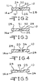
- Fig. 2 illustrates a cross-section of the oil groove 20 at the location of the bridge 22.
- a reduced area flow channel 30 is illustrated while
- Fig. 3 shows a cross-section of the oil groove 20 immediately on the downstream side of the bridge 22.
- a completely open flow channel section 31 is shown.
- the outlet bridge 23 (see Fig. 5) has a reduced thickness and defines a more open flow channel 33.
- the oil groove 20 has a narrower width flow channel 34 than the flow channel 33 at the bridge location in Fig. 5.
- the flow channel 33 has been widen to provide the same flow area as is found in the flow channel 34, illustrated in Fig. 4. Therefore, because the areas of the flow channels 33 and 34 are the same, there is no flow restriction or change of pressure at the location of the bridge 23.
- the thickness of the bridges 22 and 23 are 75% to 50% of the overall thickness of the segments 14a-14e, as defined by the top surface 11 and bottom surface 12.
- the first bridge 22 is compressed during bonding to restrict or control the flow rate while the second bridge 23 is compressed forming a wider channel 33 to maintain the oil groove cross-sectional area so as not to restrict oil flow.
- the bridges may be designed to control the restriction of the inlet or outlet or to render the bridges non-restrictive.
- the segmented friction member 10, according to the present invention utilizes significantly less friction material than that of a full friction material ring and is more economical as compared to cutting the oil grooves after bonding or using a support ring to hold the separated segments together during bonding and then removing the supporting ring.
- FIG. 6 and 7 Another embodiment of a segmented frictional member, according to the present invention is shown in Figs. 6 and 7 and is generally indicated by the reference number 40.
- the segmented friction member 40 is again constructed preferably of a friction paper layer and is mounted on a cover, piston or plate 41. When used in a torque converter, the plate 41 would normally include drive teeth (not shown) on the outer circumference or on the inner periphery.
- a second segmented friction member 40 is mounted on the opposite side of the plate or disc 41 to form an overall disc assembly 42.
- the segmented friction member 40 includes a plurality of interlocked segments 44a-44e.
- each of the segments 44a-44e includes a first end 46 which defines a recess 47 and a second end 48 which defines a tab 49.
- the tabs and recesses 47 and 49 of the segments 44a-44e are interlocked with the adjacent segments to form the complete circular segmented friction member 40, as shown in Fig. 7.
- a groove 51 extends completely through the individual segments 44a-44e and follows a path which is generally concentric with the outer periphery 52 of the friction member 40.
- An inlet 54 extends from the outer periphery 52 and an outlet 56 extends from the opposite end of the groove 51 to an inner circumference 57 of the segmented friction member 40.
- a first bridge 59 is provided at the fluid inlet 54 adjacent the groove 51 and a second bridge 60 is provided in the fluid outlet 56 adjacent the groove 60.
- the thickness of the bridge 59 is more than 50% of the thickness of the segmented friction member 40 while the second bridge 60 is approximately 50% of the thickness of the segmented friction member 40.
- the bridges are compressed to a thickness of between 50% and 75% of the thickness of the friction. Therefore, as fluid, such as oil enters the inlet 54, the area of the inlet is reduced at the first bridge 59 thereby increasing the pressure a desired amount while the cross-sectional area of the second bridge 60 closely approximates the adjacent area of the oil groove 60. This allows a flow of cooling fluid, such as oil across the second bridge 60 without a pressure build up.
Landscapes
- Engineering & Computer Science (AREA)
- General Engineering & Computer Science (AREA)
- Mechanical Engineering (AREA)
- Mechanical Operated Clutches (AREA)
- Braking Arrangements (AREA)
Abstract
Description
- Circular friction members are well known in the art and are often used in clutch assemblies. The term clutch assembly as used in the present specification and claims is used as a generic term and includes apparatus such as torque converters in addition to many other "clutches".
- United States Patent No. 5,669,474 discloses the use of a circular friction lining used in a torque converter assembly. This patent also discloses oil grooves defined in the friction lining.
- The friction members are often constructed from a paper based friction material having a frictional outer surface.
- The generally circular friction member is positioned on one or both sides of a circular support disc, which is normally a metal disc. This overall disk assembly is then positioned within a clutch assembly.
- Segmented friction members are also known in the art. A segmented friction member is, for example, shown in United States Patent No. 5,332,075. It is also known in the prior art to provide grooves in the friction lining to serve as paths for a cooling fluid, such as oil. The oil is used to cool the disc assembly. For efficient cooling, the volume of oil must be substantial. At one time in the prior art, the groove depth in the prior art friction members was approximately 25% to 50% of the thickness of the friction member. However, to increase the cooling capacity, it is not unusual to extend the oil groove completely through the friction member. This maximizes the heat transfer from the oil coming in direct contact with the support plate. It has been found that these through grooves in the prior art render the prior art friction member weak and difficult to handle before bonding to a support plate.
- With the oil groove extending completely through the prior art friction member, it was often necessary to cut the oil grooves after bonding the prior art friction member to the support plate or in the alternative, to use a separate support member, such as a support ring to hold the pieces of the prior art friction member segments in a proper position before bonding to the support disc or plate. The support rings were removed after bonding.
- The present invention is directed to an improved segmented friction member for use in a disc assembly for a wet-running friction clutch. One preferred use is in a torque converter.
- The improved segmented friction member is generally circular. The segmented friction member includes a plurality of arcuate segments having opposed ends. The ends are engaged with mating ends of adjoining segments of each segment. Each of the segments defines an elongated oil groove which separates each of the arcuate segments into an outer section and an inner section. An oil groove inlet is in communication with a first end of the elongated oil groove and an oil outlet is in communication with the second end of the elongated oil groove. First and second bridges connect the inner section with the outer section.
-
- Fig. 1 is a plan view of a segmented friction member, according to the present invention;
- Fig. 2 is a cross-sectional view, on an enlarged scale, taken along the line that 2-2 of Fig. 1;
- Fig. 3 is a cross-sectional view, on an enlarged scale, taken along the line 3-3 of Fig. 1;
- Fig. 4 is a cross-sectional view, on an enlarged scale, taken along the line 4-4 of Fig. 1;
- Fig. 5 is a cross-sectional view, on an enlarged scale, taken along the line 5-5 of Fig. 1;
- Fig. 6 is a plan view of a segment of another embodiment of a friction member, according to the present invention; and
- Fig. 7 is a perspective view of a disc assembly including the Fig. 6 embodiment of a segmented friction member, according to the present invention.
-
- Referring to Fig. 1, a segmented friction member, according to the present invention, is indicated in Fig. 1 by the
reference number 10. Thefriction member 10 is circular and is normally constructed of a paper-like material. However, thefriction member 10 may be constructed other materials such plastic, metals, nylon and carbon, including non-woven carbon materials. The segmentedfriction member 10 has atop surface 11 and abottom surface 12. The segmentedfriction member 10 includes a plurality ofarcuate segments segments 14a-14e has opposedends end 15 defines atab 17 while the opposedend 16 defines amating recess 18. Theopposed ends segments 14a-14e mate with one another as shown in Fig. 1 to form the overall circular segmentedfriction member 10. - Each of the
segments 14a-14e defines anelongated oil groove 20. In the present embodiment, illustrated in Fig. 1, theoil groove 20 has a serpentine path extending along the arcuate length of thesegment 14 and extends completely through thesegments 14 with the exception of a pair ofbridges segments 14a-14e defines anoil inlet 25 adjacent theouter periphery 26 of thefriction member 10 and anoil outlet 27 adjacent theinner periphery 28 of thefriction member 10. Preferably thebridge 22 is positioned adjacent theoil inlet 25 and thebridge 23 is positioned adjacent theoil outlet 27. Additional oil inlets and outlets may be provided, which communicate with thegroove 20. The remainder of theoil groove 20 extends completely through the segmentedfriction member 10 from thetop surface 11 to thebottom surface 12. The present construction allows thesegmented friction member 10 to be die cut during manufacture as opposed to, for example, having the oil groove milled after thefriction member 10 is adhered or positioned on the support plate of the overall disc assembly. - By having the
oil groove 20 extend completely through the segmentedfriction member 10, maximum desired fluid cooling is achieved. - The
bridges bridges bridges inner section 24 andouter section 29. Thebridges inner section 24 andouter section 29 together as a unit even though the remaining portion of theoil groove 20 extends from thetop surface 11 to thebottom surface 12. In the embodiment shown in Fig. 1, theinlet bridge 22 is compressed less than 50% of the depth defined by thetop surface 11 andbottom surface 12 of thefriction member 10. The height or thickness of thebridges friction member 10. Preferably, theinlet 22 has a thickness of 70% of the thickness of thefriction member 10. Theoutlet bridge 23 has a preferable thickness of approximately 50% of the thickness of thefriction member 10. This restricts oil flow across thebridge 22, thereby adjusting the pressure of the oil within thegroove 20. - Fig. 2 illustrates a cross-section of the
oil groove 20 at the location of thebridge 22. A reducedarea flow channel 30 is illustrated while Fig. 3 shows a cross-section of theoil groove 20 immediately on the downstream side of thebridge 22. A completely openflow channel section 31 is shown. - At the other end of the
segments 14, the outlet bridge 23 (see Fig. 5) has a reduced thickness and defines a moreopen flow channel 33. Theoil groove 20 has a narrowerwidth flow channel 34 than theflow channel 33 at the bridge location in Fig. 5. Theflow channel 33 has been widen to provide the same flow area as is found in theflow channel 34, illustrated in Fig. 4. Therefore, because the areas of theflow channels bridge 23. - Normally, the thickness of the
bridges segments 14a-14e, as defined by thetop surface 11 andbottom surface 12. As indicated above, thefirst bridge 22 is compressed during bonding to restrict or control the flow rate while thesecond bridge 23 is compressed forming awider channel 33 to maintain the oil groove cross-sectional area so as not to restrict oil flow. The bridges may be designed to control the restriction of the inlet or outlet or to render the bridges non-restrictive. - The
segmented friction member 10, according to the present invention, utilizes significantly less friction material than that of a full friction material ring and is more economical as compared to cutting the oil grooves after bonding or using a support ring to hold the separated segments together during bonding and then removing the supporting ring. - Another embodiment of a segmented frictional member, according to the present invention is shown in Figs. 6 and 7 and is generally indicated by the
reference number 40. Thesegmented friction member 40 is again constructed preferably of a friction paper layer and is mounted on a cover, piston orplate 41. When used in a torque converter, theplate 41 would normally include drive teeth (not shown) on the outer circumference or on the inner periphery. In the present embodiment, referring to Fig. 7, a secondsegmented friction member 40 is mounted on the opposite side of the plate ordisc 41 to form anoverall disc assembly 42. Thesegmented friction member 40 includes a plurality of interlockedsegments 44a-44e. - As best shown in Fig. 6, each of the
segments 44a-44e includes afirst end 46 which defines arecess 47 and asecond end 48 which defines atab 49. The tabs and recesses 47 and 49 of thesegments 44a-44e, are interlocked with the adjacent segments to form the complete circularsegmented friction member 40, as shown in Fig. 7. Agroove 51 extends completely through theindividual segments 44a-44e and follows a path which is generally concentric with theouter periphery 52 of thefriction member 40. Aninlet 54 extends from theouter periphery 52 and anoutlet 56 extends from the opposite end of thegroove 51 to aninner circumference 57 of the segmentedfriction member 40. Afirst bridge 59 is provided at thefluid inlet 54 adjacent thegroove 51 and asecond bridge 60 is provided in thefluid outlet 56 adjacent thegroove 60. - In the present embodiment, the thickness of the
bridge 59 is more than 50% of the thickness of the segmentedfriction member 40 while thesecond bridge 60 is approximately 50% of the thickness of the segmentedfriction member 40. Normally, the bridges are compressed to a thickness of between 50% and 75% of the thickness of the friction. Therefore, as fluid, such as oil enters theinlet 54, the area of the inlet is reduced at thefirst bridge 59 thereby increasing the pressure a desired amount while the cross-sectional area of thesecond bridge 60 closely approximates the adjacent area of theoil groove 60. This allows a flow of cooling fluid, such as oil across thesecond bridge 60 without a pressure build up. - Many revisions may be made to the above-described embodiments without departing from the scope of the present invention or from the following claims.
Claims (9)
- A segmented friction member for use in a clutch assembly, said friction member being generally circular and having a top surface and a bottom surface, said segmented friction member including a plurality of arcuate segments having opposed ends, said ends being engaged with mating ends of adjoining arcuate segments, each of said segments defining an elongated oil groove, said oil groove separating said arcuate segment into an outer section and an inner section, an oil groove inlet in communication with a first end of said elongated oil groove and an oil outlet in communication with second end of said elongated oil groove, and first and second bridges extending between said outer section and said inner section, whereby said first and second bridges connect said inner and outer section of said arcuate segment.
- A segmented friction member, according to claim 1, wherein said segmented friction member comprises a paper based friction layer and each of said bridges comprises a compressed portion of said paper based friction layer.
- A segmented friction member, according to claim 1 or 2, wherein said first bridge is adjacent said oil inlet, said oil groove having a flow channel area adjacent said first bridge said oil groove having a reduced flow channel area at said first bridge.
- A segmented friction member, according to any one of claims 1 to 3, wherein said second bridge is adjacent said oil outlet, said groove having a flow channel area adjacent said second bridge, said oil groove being wider and having the same flow channel area at said second bridge.
- A segmented friction member, according to any one of claims 1 to 4, wherein said first and said second bridges have a thickness of between 50% and 75% of the thickness of said friction member.
- A generally circular friction member for use in a clutch assembly, having a top surface and a bottom surface; at least one oil groove defined by a slot extending from the top surface to the bottom surface, the oil groove extending in the circumferential direction of the friction member from an oil groove inlet on the outer periphery of the friction member to an oil groove outlet on the inner periphery of the friction member; and first and second bridges extending across each slot, connecting opposite sides thereof.
- An arcuate segment for use in a segmental friction member, having a top surface and a bottom surface, the arcuate segment having opposed ends for mating engagement with like arcuate segments; the arcuate segment comprising an outer section and an inner section defining an elongated oil slot therebetween, the oil slot having an inlet at a first end of the slot and an outlet at a second end; and first and second bridges extending between the inner and outer sections, the bridges connecting the inner and outer sections.
- A friction member according to any one of claims 1 to 6 or an arcuate segment according to claim 7, wherein the oil groove defines a serpentine path, longer than the arc between the oil inlet and the oil outlet.
- A friction member according to any one of claims 1 to 6 or an arcuate segment according to claims 7 or 8 wherein five arcuate segments are required to form a complete circular friction member.
Applications Claiming Priority (2)
| Application Number | Priority Date | Filing Date | Title |
|---|---|---|---|
| US562486 | 2000-05-01 | ||
| US09/562,486 US6345711B1 (en) | 2000-05-01 | 2000-05-01 | Segmented friction member |
Publications (2)
| Publication Number | Publication Date |
|---|---|
| EP1152160A1 true EP1152160A1 (en) | 2001-11-07 |
| EP1152160B1 EP1152160B1 (en) | 2003-06-11 |
Family
ID=24246474
Family Applications (1)
| Application Number | Title | Priority Date | Filing Date |
|---|---|---|---|
| EP01303970A Expired - Lifetime EP1152160B1 (en) | 2000-05-01 | 2001-04-30 | Segmented friction member |
Country Status (5)
| Country | Link |
|---|---|
| US (1) | US6345711B1 (en) |
| EP (1) | EP1152160B1 (en) |
| JP (1) | JP2001355649A (en) |
| KR (1) | KR100757107B1 (en) |
| DE (1) | DE60100351T2 (en) |
Cited By (3)
| Publication number | Priority date | Publication date | Assignee | Title |
|---|---|---|---|---|
| FR2856453A1 (en) * | 2003-06-17 | 2004-12-24 | Valeo Embrayages | HYDROKINETIC COUPLING APPARATUS, ESPECIALLY FOR A MOTOR VEHICLE, AND FRICTION FITTING FOR SUCH AN APPARATUS |
| EP1876369A3 (en) * | 2006-07-05 | 2011-01-19 | ZF Friedrichshafen AG | Friction disc for the wet coupling of a vehicle |
| CN103573883A (en) * | 2012-07-26 | 2014-02-12 | 博格华纳公司 | Friction component for device operating in friction connecting method |
Families Citing this family (15)
| Publication number | Priority date | Publication date | Assignee | Title |
|---|---|---|---|---|
| US6793363B2 (en) * | 2002-12-13 | 2004-09-21 | Christopher A. Jensen | Illuminated coaster |
| US7014024B2 (en) * | 2003-06-11 | 2006-03-21 | Sulzer Euroflamm Us Inc. | System and method for improving cooling in a friction facing environment |
| US7069636B2 (en) | 2003-10-02 | 2006-07-04 | Euroflamm Select Inc. | Friction facing method for use in a friction environment |
| US7168544B2 (en) * | 2003-10-02 | 2007-01-30 | Sulzer Euroflamm Us Inc. | Friction facing material for use in a friction environment |
| US20060236523A1 (en) * | 2003-10-02 | 2006-10-26 | Sulzer Euroflamm Us Inc | Friction facing method for use in a friction environment |
| JP2009503416A (en) * | 2005-08-04 | 2009-01-29 | ボーグワーナー・インコーポレーテッド | Friction plate and various manufacturing methods thereof |
| JP5289967B2 (en) * | 2005-11-01 | 2013-09-11 | ボーグワーナー インコーポレーテッド | Split and laminated steel core plates for single-sided and / or double-sided wet clutch friction plates or separator plates |
| KR101286258B1 (en) * | 2006-02-21 | 2013-07-15 | 보르그워너 인코퍼레이티드 | Segmented core plate and friction disc |
| US20070270069A1 (en) * | 2006-05-18 | 2007-11-22 | Sulzer Euroflamm Us Inc. | Friction material and system and method for making the friction material |
| DE102006057112B4 (en) * | 2006-12-05 | 2018-08-30 | Borg Warner Inc. | Friction member for a frictionally-operating device and frictionally-operating device with such a friction member |
| KR101462245B1 (en) * | 2007-08-15 | 2014-11-17 | 보르그워너 인코퍼레이티드 | Frictional part with a zig-zag or undulating circumferential groove in the frictional surface |
| CN103299100B (en) * | 2010-12-13 | 2016-06-08 | 舍弗勒技术股份两合公司 | Method for manufacturing friction body |
| USD709114S1 (en) | 2011-12-16 | 2014-07-15 | Eaton Corporation | Friction plate for a clutch |
| US8939269B2 (en) | 2011-12-16 | 2015-01-27 | Eaton Corporation | Segmented friction material for clutches |
| CA3029422A1 (en) | 2016-07-01 | 2018-01-04 | Linamar Corporation | A controllable powertrain input module |
Citations (4)
| Publication number | Priority date | Publication date | Assignee | Title |
|---|---|---|---|---|
| US4260047A (en) * | 1979-12-03 | 1981-04-07 | General Motors Corporation | Friction disc and method of making same |
| US5332075A (en) * | 1993-01-06 | 1994-07-26 | Borg-Warner Automotive, Inc. | Friction disc with segmented friction facing |
| US5566802A (en) * | 1995-07-17 | 1996-10-22 | Borg-Warner Automotive, Inc. | Continuous slip hydrokinetic torque converter clutch interface with curcuitous groove for cooling and wetting clutch interface zone |
| EP0838611A2 (en) * | 1996-10-23 | 1998-04-29 | Borg-Warner Automotive Transmission And Engine Components Corporation | Functionally enhanced hydrokinetic device having clutch assembly operable at low engine speeds |
Family Cites Families (7)
| Publication number | Priority date | Publication date | Assignee | Title |
|---|---|---|---|---|
| US4674616A (en) * | 1983-01-31 | 1987-06-23 | Borg-Warner Corporation | Friction disc with segmented core plate and facings |
| JPS6282428U (en) * | 1985-11-12 | 1987-05-26 | ||
| JPS6298832U (en) * | 1985-12-12 | 1987-06-24 | ||
| DE19500814B4 (en) * | 1994-01-21 | 2013-09-12 | Schaeffler Technologies AG & Co. KG | Friction ring and clutch with such a friction ring |
| DE4432624C1 (en) | 1994-09-14 | 1996-04-04 | Fichtel & Sachs Ag | Hydrodynamic torque converter with a lock-up clutch |
| US5771691A (en) * | 1996-10-23 | 1998-06-30 | Borg-Warner Automotive, Inc. | Torque converter having spatially oriented flat turbine blades |
| US6035991A (en) * | 1996-12-11 | 2000-03-14 | Advanced Friction Materials, Inc. | Blocked slot clutch plate lining |
-
2000
- 2000-05-01 US US09/562,486 patent/US6345711B1/en not_active Expired - Lifetime
-
2001
- 2001-04-30 EP EP01303970A patent/EP1152160B1/en not_active Expired - Lifetime
- 2001-04-30 DE DE60100351T patent/DE60100351T2/en not_active Expired - Lifetime
- 2001-05-01 JP JP2001133838A patent/JP2001355649A/en active Pending
- 2001-05-02 KR KR1020010023869A patent/KR100757107B1/en not_active Expired - Fee Related
Patent Citations (4)
| Publication number | Priority date | Publication date | Assignee | Title |
|---|---|---|---|---|
| US4260047A (en) * | 1979-12-03 | 1981-04-07 | General Motors Corporation | Friction disc and method of making same |
| US5332075A (en) * | 1993-01-06 | 1994-07-26 | Borg-Warner Automotive, Inc. | Friction disc with segmented friction facing |
| US5566802A (en) * | 1995-07-17 | 1996-10-22 | Borg-Warner Automotive, Inc. | Continuous slip hydrokinetic torque converter clutch interface with curcuitous groove for cooling and wetting clutch interface zone |
| EP0838611A2 (en) * | 1996-10-23 | 1998-04-29 | Borg-Warner Automotive Transmission And Engine Components Corporation | Functionally enhanced hydrokinetic device having clutch assembly operable at low engine speeds |
Cited By (7)
| Publication number | Priority date | Publication date | Assignee | Title |
|---|---|---|---|---|
| FR2856453A1 (en) * | 2003-06-17 | 2004-12-24 | Valeo Embrayages | HYDROKINETIC COUPLING APPARATUS, ESPECIALLY FOR A MOTOR VEHICLE, AND FRICTION FITTING FOR SUCH AN APPARATUS |
| WO2005001313A1 (en) * | 2003-06-17 | 2005-01-06 | Valeo Embrayages | Hydrokinetic coupling device which is intended, for example, for a motor vehicle, and friction lining for one such device |
| CN100436879C (en) * | 2003-06-17 | 2008-11-26 | Valeo离合器公司 | Fluid power coupling device for motor vehicle and friction plate of the device |
| EP1876369A3 (en) * | 2006-07-05 | 2011-01-19 | ZF Friedrichshafen AG | Friction disc for the wet coupling of a vehicle |
| US8113330B2 (en) | 2006-07-05 | 2012-02-14 | Zf Friedrichshafen Ag | Friction disk for a wet-running clutch for a motor vehicle |
| US8205734B2 (en) | 2006-07-05 | 2012-06-26 | Zf Friedrichshafen Ag | Friction disk for a wet-running clutch for a motor vehicle |
| CN103573883A (en) * | 2012-07-26 | 2014-02-12 | 博格华纳公司 | Friction component for device operating in friction connecting method |
Also Published As
| Publication number | Publication date |
|---|---|
| DE60100351D1 (en) | 2003-07-17 |
| KR20010100963A (en) | 2001-11-14 |
| EP1152160B1 (en) | 2003-06-11 |
| US6345711B1 (en) | 2002-02-12 |
| JP2001355649A (en) | 2001-12-26 |
| KR100757107B1 (en) | 2007-09-10 |
| DE60100351T2 (en) | 2003-12-04 |
Similar Documents
| Publication | Publication Date | Title |
|---|---|---|
| US6345711B1 (en) | Segmented friction member | |
| US6062367A (en) | Friction plate | |
| US5460255A (en) | Universal segmented friction clutch facing | |
| EP0848177B1 (en) | Blocked slot clutch plate lining | |
| JPH10184721A (en) | Disk assembly | |
| JP4297308B2 (en) | Wet friction member | |
| US4674616A (en) | Friction disc with segmented core plate and facings | |
| EP0833069B1 (en) | Friction disc with segmented friction facing | |
| CN101375075B (en) | Segmented core plate and friction plate | |
| EP2028383A2 (en) | Wet friction material | |
| KR100508013B1 (en) | Plate and facing assembly | |
| KR100941519B1 (en) | Disc and friction lining for power train | |
| US7073650B2 (en) | Friction plate groove pattern | |
| US20020162721A1 (en) | Oil cooling of clutch package | |
| CA2396403A1 (en) | Wet friction plate assembly | |
| US6505723B1 (en) | Multi-disc clutch separator plate | |
| US6145645A (en) | Disk assembly | |
| JPH0672619B2 (en) | Friction disc | |
| JP2004245420A (en) | Clutching plate with cooling flow path | |
| JP4756555B2 (en) | Friction facing and method for providing friction facing | |
| JPH0650353A (en) | Friction engagement device | |
| US20210071726A1 (en) | Friction plate and friction engagement device provided with the same | |
| KR20180027548A (en) | A friction member for a friction-shifting member for a vehicle transmission | |
| JP2005069411A (en) | Segment type frictional material |
Legal Events
| Date | Code | Title | Description |
|---|---|---|---|
| PUAI | Public reference made under article 153(3) epc to a published international application that has entered the european phase |
Free format text: ORIGINAL CODE: 0009012 |
|
| AK | Designated contracting states |
Kind code of ref document: A1 Designated state(s): DE FR GB IT Kind code of ref document: A1 Designated state(s): AT BE CH CY DE DK ES FI FR GB GR IE IT LI LU MC NL PT SE TR |
|
| AX | Request for extension of the european patent |
Free format text: AL;LT;LV;MK;RO;SI |
|
| 17P | Request for examination filed |
Effective date: 20020405 |
|
| AKX | Designation fees paid |
Free format text: DE FR GB IT |
|
| 17Q | First examination report despatched |
Effective date: 20020617 |
|
| GRAH | Despatch of communication of intention to grant a patent |
Free format text: ORIGINAL CODE: EPIDOS IGRA |
|
| GRAH | Despatch of communication of intention to grant a patent |
Free format text: ORIGINAL CODE: EPIDOS IGRA |
|
| RAP1 | Party data changed (applicant data changed or rights of an application transferred) |
Owner name: BORGWARNER INC. |
|
| GRAA | (expected) grant |
Free format text: ORIGINAL CODE: 0009210 |
|
| AK | Designated contracting states |
Designated state(s): DE FR GB IT |
|
| REG | Reference to a national code |
Ref country code: GB Ref legal event code: FG4D |
|
| REF | Corresponds to: |
Ref document number: 60100351 Country of ref document: DE Date of ref document: 20030717 Kind code of ref document: P |
|
| ET | Fr: translation filed | ||
| PLBE | No opposition filed within time limit |
Free format text: ORIGINAL CODE: 0009261 |
|
| STAA | Information on the status of an ep patent application or granted ep patent |
Free format text: STATUS: NO OPPOSITION FILED WITHIN TIME LIMIT |
|
| 26N | No opposition filed |
Effective date: 20040312 |
|
| PGFP | Annual fee paid to national office [announced via postgrant information from national office to epo] |
Ref country code: GB Payment date: 20090312 Year of fee payment: 9 |
|
| PGFP | Annual fee paid to national office [announced via postgrant information from national office to epo] |
Ref country code: IT Payment date: 20090418 Year of fee payment: 9 |
|
| GBPC | Gb: european patent ceased through non-payment of renewal fee |
Effective date: 20100430 |
|
| PG25 | Lapsed in a contracting state [announced via postgrant information from national office to epo] |
Ref country code: GB Free format text: LAPSE BECAUSE OF NON-PAYMENT OF DUE FEES Effective date: 20100430 Ref country code: IT Free format text: LAPSE BECAUSE OF NON-PAYMENT OF DUE FEES Effective date: 20100430 |
|
| REG | Reference to a national code |
Ref country code: FR Ref legal event code: PLFP Year of fee payment: 16 |
|
| REG | Reference to a national code |
Ref country code: FR Ref legal event code: PLFP Year of fee payment: 17 |
|
| REG | Reference to a national code |
Ref country code: FR Ref legal event code: PLFP Year of fee payment: 18 |
|
| PGFP | Annual fee paid to national office [announced via postgrant information from national office to epo] |
Ref country code: FR Payment date: 20180320 Year of fee payment: 18 |
|
| PGFP | Annual fee paid to national office [announced via postgrant information from national office to epo] |
Ref country code: DE Payment date: 20180409 Year of fee payment: 18 |
|
| REG | Reference to a national code |
Ref country code: DE Ref legal event code: R119 Ref document number: 60100351 Country of ref document: DE |
|
| PG25 | Lapsed in a contracting state [announced via postgrant information from national office to epo] |
Ref country code: DE Free format text: LAPSE BECAUSE OF NON-PAYMENT OF DUE FEES Effective date: 20191101 |
|
| PG25 | Lapsed in a contracting state [announced via postgrant information from national office to epo] |
Ref country code: FR Free format text: LAPSE BECAUSE OF NON-PAYMENT OF DUE FEES Effective date: 20190430 |