EP1152148B1 - Airfoil profiles for wind turbines - Google Patents
Airfoil profiles for wind turbines Download PDFInfo
- Publication number
- EP1152148B1 EP1152148B1 EP01110591A EP01110591A EP1152148B1 EP 1152148 B1 EP1152148 B1 EP 1152148B1 EP 01110591 A EP01110591 A EP 01110591A EP 01110591 A EP01110591 A EP 01110591A EP 1152148 B1 EP1152148 B1 EP 1152148B1
- Authority
- EP
- European Patent Office
- Prior art keywords
- airfoil
- chord
- design
- approximately
- airfoils
- Prior art date
- Legal status (The legal status is an assumption and is not a legal conclusion. Google has not performed a legal analysis and makes no representation as to the accuracy of the status listed.)
- Revoked
Links
- 238000013461 design Methods 0.000 claims abstract description 120
- 238000000034 method Methods 0.000 abstract description 12
- 238000004519 manufacturing process Methods 0.000 abstract description 10
- 238000005457 optimization Methods 0.000 abstract description 5
- 238000012916 structural analysis Methods 0.000 abstract description 2
- 238000009826 distribution Methods 0.000 description 16
- 230000000694 effects Effects 0.000 description 14
- 230000007423 decrease Effects 0.000 description 12
- 238000004458 analytical method Methods 0.000 description 8
- 230000001105 regulatory effect Effects 0.000 description 6
- 230000003746 surface roughness Effects 0.000 description 6
- 230000009467 reduction Effects 0.000 description 5
- 238000013459 approach Methods 0.000 description 4
- 230000008901 benefit Effects 0.000 description 4
- 238000010586 diagram Methods 0.000 description 4
- 239000011888 foil Substances 0.000 description 4
- 230000006872 improvement Effects 0.000 description 4
- 230000002829 reductive effect Effects 0.000 description 4
- 230000003467 diminishing effect Effects 0.000 description 3
- 230000002349 favourable effect Effects 0.000 description 3
- 238000012360 testing method Methods 0.000 description 3
- 238000005452 bending Methods 0.000 description 2
- 230000009286 beneficial effect Effects 0.000 description 2
- 239000002131 composite material Substances 0.000 description 2
- 238000010276 construction Methods 0.000 description 2
- 230000000670 limiting effect Effects 0.000 description 2
- 238000004904 shortening Methods 0.000 description 2
- 230000003068 static effect Effects 0.000 description 2
- 238000004364 calculation method Methods 0.000 description 1
- 238000004590 computer program Methods 0.000 description 1
- 230000003247 decreasing effect Effects 0.000 description 1
- 238000012938 design process Methods 0.000 description 1
- 238000011161 development Methods 0.000 description 1
- 238000013178 mathematical model Methods 0.000 description 1
- 238000012986 modification Methods 0.000 description 1
- 230000004048 modification Effects 0.000 description 1
- 238000011084 recovery Methods 0.000 description 1
- 238000011160 research Methods 0.000 description 1
- 230000002441 reversible effect Effects 0.000 description 1
- 230000009291 secondary effect Effects 0.000 description 1
- 238000004513 sizing Methods 0.000 description 1
- 238000006467 substitution reaction Methods 0.000 description 1
- 239000002023 wood Substances 0.000 description 1
Images







Classifications
-
- F—MECHANICAL ENGINEERING; LIGHTING; HEATING; WEAPONS; BLASTING
- F03—MACHINES OR ENGINES FOR LIQUIDS; WIND, SPRING, OR WEIGHT MOTORS; PRODUCING MECHANICAL POWER OR A REACTIVE PROPULSIVE THRUST, NOT OTHERWISE PROVIDED FOR
- F03D—WIND MOTORS
- F03D1/00—Wind motors with rotation axis substantially parallel to the air flow entering the rotor
- F03D1/06—Rotors
- F03D1/0608—Rotors characterised by their aerodynamic shape
- F03D1/0633—Rotors characterised by their aerodynamic shape of the blades
- F03D1/0641—Rotors characterised by their aerodynamic shape of the blades of the section profile of the blades, i.e. aerofoil profile
-
- F—MECHANICAL ENGINEERING; LIGHTING; HEATING; WEAPONS; BLASTING
- F05—INDEXING SCHEMES RELATING TO ENGINES OR PUMPS IN VARIOUS SUBCLASSES OF CLASSES F01-F04
- F05B—INDEXING SCHEME RELATING TO WIND, SPRING, WEIGHT, INERTIA OR LIKE MOTORS, TO MACHINES OR ENGINES FOR LIQUIDS COVERED BY SUBCLASSES F03B, F03D AND F03G
- F05B2240/00—Components
- F05B2240/20—Rotors
- F05B2240/30—Characteristics of rotor blades, i.e. of any element transforming dynamic fluid energy to or from rotational energy and being attached to a rotor
- F05B2240/301—Cross-section characteristics
-
- Y—GENERAL TAGGING OF NEW TECHNOLOGICAL DEVELOPMENTS; GENERAL TAGGING OF CROSS-SECTIONAL TECHNOLOGIES SPANNING OVER SEVERAL SECTIONS OF THE IPC; TECHNICAL SUBJECTS COVERED BY FORMER USPC CROSS-REFERENCE ART COLLECTIONS [XRACs] AND DIGESTS
- Y02—TECHNOLOGIES OR APPLICATIONS FOR MITIGATION OR ADAPTATION AGAINST CLIMATE CHANGE
- Y02E—REDUCTION OF GREENHOUSE GAS [GHG] EMISSIONS, RELATED TO ENERGY GENERATION, TRANSMISSION OR DISTRIBUTION
- Y02E10/00—Energy generation through renewable energy sources
- Y02E10/70—Wind energy
- Y02E10/72—Wind turbines with rotation axis in wind direction
-
- Y—GENERAL TAGGING OF NEW TECHNOLOGICAL DEVELOPMENTS; GENERAL TAGGING OF CROSS-SECTIONAL TECHNOLOGIES SPANNING OVER SEVERAL SECTIONS OF THE IPC; TECHNICAL SUBJECTS COVERED BY FORMER USPC CROSS-REFERENCE ART COLLECTIONS [XRACs] AND DIGESTS
- Y10—TECHNICAL SUBJECTS COVERED BY FORMER USPC
- Y10S—TECHNICAL SUBJECTS COVERED BY FORMER USPC CROSS-REFERENCE ART COLLECTIONS [XRACs] AND DIGESTS
- Y10S416/00—Fluid reaction surfaces, i.e. impellers
- Y10S416/02—Formulas of curves
-
- Y—GENERAL TAGGING OF NEW TECHNOLOGICAL DEVELOPMENTS; GENERAL TAGGING OF CROSS-SECTIONAL TECHNOLOGIES SPANNING OVER SEVERAL SECTIONS OF THE IPC; TECHNICAL SUBJECTS COVERED BY FORMER USPC CROSS-REFERENCE ART COLLECTIONS [XRACs] AND DIGESTS
- Y10—TECHNICAL SUBJECTS COVERED BY FORMER USPC
- Y10S—TECHNICAL SUBJECTS COVERED BY FORMER USPC CROSS-REFERENCE ART COLLECTIONS [XRACs] AND DIGESTS
- Y10S416/00—Fluid reaction surfaces, i.e. impellers
- Y10S416/05—Variable camber or chord length
Definitions
- the subject invention is generally related to wind power turbines and is specifically directed to a family of airfoil configurations for optimizing the performance of the wind turbine.
- Wind power turbines are well known.
- the turbine blades or airfoils are one of the primary factors in determining the efficiency of the system and thus are a critical factor in optimizing performance.
- the turbine rotor blade design proceeds by first identifying a family of airfoils to be employed and then determining the optimum spanwise distribution of solidity and twist in order to optimize the power coefficient at each spanwise location. This procedure often does not result in the structurally optimal blade for the specific application.
- Various efforts to optimize the blade configuration have been used over the years, with varying results.
- Zond Energy Systems, Inc. (the Assignee of the subject invention) has generally used a thinner airfoil configuration than its European counterparts.
- the 34 meter blades manufactured by LM Glasfibre for Tacke's 70 meter TW1.5s system employ a 39% thick section at the 25% spanwise location as compared t a 24% thick section on the comparable Zond Z46/48/50 blades. Even at 40% span, the airfoil section is 30% thick. This has a significant impact upon drag, reducing the energy capture from these blades by as much as 10%.
- Turbines currently on the market have rotor loading of approximately 0.42-0.45kW/m 2 for machines certified IEC Class 1, 0.38-0.41kW/ m 2 for Class 2 and 0.33-0.38kW/m 2 for Class 3. Taking a given wind turbine and then scaling both the rotor and drive train, including the generator, in proportion to each other it is a fairly straightforward series of calculations to determine the dependence of blade loads upon rotor size. If it is assumed that the rotor aerodynamics and solidity remain constant as the rotor is scaled, then the rated wind speed will remain constant for the various sized machines. For a turbine such as Zond's 750 kW series, the tip speed of 85 m/s is approximately the higher limit.
- ⁇ rated V tip /R
- ⁇ rated the rated shaft speed
- V tip the fixed tip speed
- R the rotor radius
- US 4,976,587 discloses a wind turbine rotor blade including NASA LS(1)-04xx airfoil sections having a twist not greater than 8 degrees and a construction for such a blade which includes not parting line along the leading edge.
- the bond between a rectangular spar and the outer skin is reinforced by channels of "C"-shaped cross-section fixed to the skin and the spar.
- US 4,976,587 discloses a method for manufacturing a rotor blade of this construction.
- US 4,519,746 discloses an improved airfoil blade for aircraft propellers and the like which exhibits high aerodynamic performance and low far and near field noise levels at a minimum weight is provided with a high lift and high lift to track cross-sectional airfoil shape characterized by a blunt, generally parabolic leading edge portion which fairs into a pressure surface characterized by a leading convex portion.
- the pressure surface includes a concave trailing portion at one and thereof fairing into the leading convex portion and at the other end thereof, terminating at a blunt trailing edge.
- the leading edge portion also fairs into a suction surface which is convex along substantially the entire length thereof to the blade trailing edge.
- stall-regulated rotors For stall-regulated rotors, a better peak-power control is achieved through the design tip airfoils that restrain the maximum lift coefficient. Restrained maximum lift coefficient allows the use of more swept disk area for a given generator size.
- tip airfoils with high thickness are used to accommodate all the speed control devices.
- tip airfoils having a high maximum lift coefficient lend themselves to light weight blades with low solidity. Tip airfoils having low thickness result in less track for blades having full span pitch control.
- US 4,844,698 discloses a propeller having blades designed to achieve maximum threst at lower static velocities in both forward and reverse pitch modes.
- Each blade has a generous leading edge radius leading to an upper surface having positive camber and a lower surface having positive camber adjacent the leading edge and negative camber adjacent the trailing edge.
- Each blade also has a high thickness-to-chord ratio and lower span-to-chord ratio or aspect ratio. This thick blade profile and aft loading leads to a more uniform pressure distribution and laminar air flow across the blade surface resulting in a higher coefficient of lift, increased blade life and reliability, and lower noise levels.
- EP 0 675 285 A1 discloses airfoils for the blade of a wind turbine wherein each airfoil is characterized by a thickness in a range from 16 % -24 % and a maximum lift coefficient designed to be largely insensitive to roughness effects.
- the airfoils include a family of airfoils for a blade 15 to 25 m in length, a family of air foils for a blade 1 to 5 m in length and a family or airfoils for a blade 5 to 10 m in length.
- WO 99/27252 discloses airfoils for the tip regions and mid-span regions of a wind turbine blade which have upper and lower surface shape contours between a leading edge and a trailing edge to minimize roughness effects of the air foils and provide maximum lift coefficients that are largely insensitive to roughness effects.
- the air foil has a thickness between about 14 - 17 %, a Reynolds number in the range of about 1,500,000 to 2,000,000, and a maximum lift coefficient in a range of about 1.4 to 1.5.
- the airfoil has a thickness between about 14 - 16 %, a Reynolds number in the range of about 1,500,000 to 3,000,000, and a maximum lift coefficient in a range of about 0.7 to 1.5.
- US 5,474,425 discloses horizontal axis, free yaw, self-regulated wind turbines which have strong, light weight, fatigue resistant, fixed pitch, wood/gre blades and exhibit superiour performance a range of wind speeds.
- the blades are designed by employing defined in-board, mid-span and out-span airfoil profiles and interpolating the profiles between the defined profiles and from the latter to the route and the tip of the blades.
- curvager maximum at the leading edge, decreases first of all rapidly to reach a value of about 8 at about 3,5 % of the length of the chord, then decreases less rapidly to reach a zero value at a point situated between 10 % and 60 % of the length of the chord, decreases further to a slightly negative value and then remains practically constant as far as the trailing edge.
- US 5,252,381 discloses an airfoil section comprising a relative thick trailing edge and a sloped rear surface.
- the combination of aerodynamic optimization and structural optimization in accordance with the teachings of the invention results in a new and novel airfoil design having substantially improved performance characteristics of airfoil designs of the prior art.
- the aforementioned mathematic modeling yields maximum aerodynamic criteria.
- This is then coupled with a structural analysis to modify the optimum aerodynamic design into a balance, substantially optimized airfoil configuration.
- the resulting airfoils of the subject invention have substantial performance impact on GAEP when compared to the airfoils of the prior art.
- the subject invention is an airfoil design based on the theoretical optimum aerodynamic structure modified as required to maximize structural integrity.
- the subject invention is the result of an effort to maximize and optimize airfoil configuration and design by determining the important characteristics of the mathematical definition of the airfoil consistent with the above prior-art recognized mathematical modeling.
- This procedure provides the criteria for maximizing airfoil performance to achieve highest GAEP while taking into consideration the aerodynamic design parameters as balanced against structural requirements.
- the methodology of the subject invention permits the design of airfoils of predictable performance while achieving necessary structural integrity.
- the subject invention has resulted in a family of airfoils having operational and structural characteristics with substantially enhanced performance capability over prior airfoils used in the same or similar applications.
- the family of airfoils includes thickness-to-chord ratios ranging from 14% to 45%.
- Equation 2 if the rotors are scaled up proportionately (i.e., the solidity remains constant), then substitution of Equation 2 into Equation 3 results in the conclusion that F x at any equivalent spanwise location (i.e., r/R) scales as the rotor diameter: F x ⁇ R
- F x q rated cC 1 sin ⁇ where ⁇ is the inflow angle.
- Equation 5 in the methodology of the subject invention the dynamic pressure at outboard station is dominated by the tangential velocity, so the drop in rated wind speed has little effect on the dynamic pressure at rated wind speed.
- Equation 5 and 12 the inflow angle varies inversely with the local speed ration and Equations 5 and 12 become: Fx ⁇ q rated cC 1 sin ⁇ ⁇ RC 1 (1/X) ⁇ RC 1 (1/X) ⁇ C 1 R 1/3
- Equation 10 for X, combining Equations 12 and 13 yields: C1 ⁇ R -4/3 at rated wind speeds.
- Equation 14 into Equation 6 yields Fy ⁇ q rated cC1cos ⁇ ⁇ R -1/3
- the root bending moment scales as the radius to the power 1.66.
- Equation 16 can be used to calculate what size rotor will result in a 15% increase in loads. For example, using a Tackes'sTW1.5s turbine with a 70.5m rotor and a 1,500kW rating it can be determined from the trade-off studies that when the stiffness of the blade is halved that the loads will be reduced 15%.
- the 70.5m rotor could be increased by 10%, to a 77m rotor without increasing the key design fatigue loads if the stiffness is relaxed two-fold. This results in a 20% increase in swept area and, assuming 50% of the energy capture comes from operation below rated, a 10% increase in net annual energy production. This example is for a rotor loading of 0.32 kW/m 2 (for IEC Class 2).
- the blade geometry is designed for maximum annual energy production.
- the optimum axial inflow of 1/3 and design lift coefficient c l are prescribed and the corresponding chord and twist/pitch are obtained using the inverse design capability of the computer program PROPID (PROPID is a commercially available design program.
- PROPID is a commercially available design program.
- a selected design c l which is the c l for which maximum lift-to-drag ratio is achieved, results in the same chord length independently of the airfoil t/c considered.
- design constraints were used:
- the design process was carried out on blade segments at four radial stations, namely 25%-30% radius, 55%-60% radius, 75%-80% radius, and 90%-95% radius.
- the design c l is prescribed to 1.05 and the airfoil thickness is varied for each of the four radial stations. Also, the airfoil thickness at each radial station was fixed and the design c l was varied. For this study on the effects of the design c l on energy capture, the airfoil t/c was fixed at 27% for station 1,21% for station 2 16% for station 3 and 12% for station 4. Entire blade design is also considered with the airfoils used along the blade defined at the same four stations as the segment designs and the hub modeled as a cylinder.
- GAEP is maximized when the airfoil t/c does not exceed 21% 18% and 14%, for the second (55%-60% radius), third (75%-80% radius), and fourth blade stations (90%-95%), respectively.
- Truncating or shortening the inboard chord should be limited to 25%-30% of the maximum nominal chord length value. Such truncation of the chord has only a small effect on the GAEP, particularly if the root airfoil is not truncated.
- airfoil design may be optimized using a balance of maximized aerodynamic and maximized structural requirements to provide a dependable, efficient airfoil with enhanced GAEP over prior art configurations.
- Equation 16 can be used to calculate what size rotor will result in a 15% decrease in loads. For example, using a Tackes'sTW1.5s turbine with a 70.5m rotor and a 1,500kW rating it can be determined from the trade-off studies that when the stiffness of the blade is halved that the loads will be reduced 15%.
- the design is modified by determining the structural characteristics and modifying from the optimized aerodynamic design in accordance the tabular information collected as shown, by way of example, in Figs. 1-13. It should be noted that the examples used for the tabulations shown in Figs. 1-13 are exemplary. The same methodology can be used for other structural configurations.
- the crux of the invention is the use of this structural data to modify the optimized aerodynamic design in order to balance the structural integrity of the airfoil with the optimum aerodynamics.
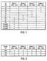
- Fig. 1 shows the t/c thickness v ⁇ considered for each radial station 1-4.
- the fifteen cases shown in Fig. 1. The airfoil thickness at each radial station is fixed and the design c l is varied in Fig. 2.
- the airfoil t/c was fixed at 27% for station 1,21% for station 2, 16% for station 3 and 12% for station 4.
- Fig. 3 shows the airfoil t/c and design c l at each station for the seven blade design cases.
- the baseline case represents a best-case scenario in terms of maximizing energy capture.
- the airfoil t/c and design c l distribution of a prior art Z-48 blade are that of case 1 b.
- Case la shows the departures from the Z-48 blade with increasing airfoil t/c with increasing design c l to counterbalance the reduction in blade chord from the use of high-lift airfoils.
- the segment designs are subdivided into two sets of cases.
- the first set covers a range of airfoil t/c for a given design c l of 1.05, and the second set considered increases in the design c l while fixing the airfoil t/c.
- the chord length is the same for a given design c l and station while the rotor thrust are the same for a given station independently of the design c l and airfoil t/c.
- Fig. 4 illustrates a comparison between GAEP of all cases shown in Fig. 1.
- the first station yields about 1/3 the GAEP of the fourth station.
- the second and third stations provide approximately 70% and 93% of the GAEP of the fourth station, respectively.
- the differences in GAEP for a given station are shown in Figs. 5-8.
- the GAEP results as a function of airfoil t/c for the first station are shown in Fig. 5.
- the axis for the GAEP represents a 10% difference.
- the decrease in GAEP with airfoil t/c is relatively small for the non-truncated airfoils, and thus the structural advantages of increasing the airfoil t/c are likely to be beneficial despite the loss in GAEP.
- Truncating the 30% thick airfoil results in a rapid loss in GAEP.
- the maximum difference in GAEP depicted in Fig. 4 corresponds to a loss in annual income of $416.00, which may be significant considering that this is for a single blade segment.
- the loss in GAEP from truncating the 30% thick airfoil should be balanced with the structural advantages that truncation provides.
- Fig. 6 presents the GAEP results for the second station and shows that an airfoil t/c of 24% corresponds to the optimum point (the point of diminishing return).
- the axis for the GAEP represents a difference of 2%. At $0.05/K ⁇ kWh, the maximum difference in annual income is $129.00. Airfoil t/c of 21%-24% are optimum for this station.
- the GAEP results for the third station are depicted in Fig. 7, for which the axis for the GAEP is again a 2% difference. Airfoil t/c of 18% is maximum.
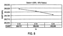
- Fig. 8 shows the GAEP results for the fourth station, with again a GAEP axis scaled for a 2% difference.
- the maximum airfoil t/c is 14%.
- Fig. 9 represents the GAEP of the twelve cases shown in Fig. 2. The relative differences between the results are similar to those for the variation in airfoil t/c.
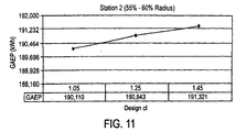
- Figs. 10-13 show the GAEP for each station with a GAEP axis corresponding to a maximum difference of 2%. Fore each station, increasing c l improved the GAEP and a design c l of 1.25 was found to be the point of diminishing return. The trend of increasing GAEP with increasing c, can be traced to the fixed amount of laminar flow of the airfoils.
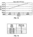
- Fig 14 shows the difference in annual income for each station assuming a price of $0.05/kWh. The difference is small for the inboard station and thus the merit of increasing the design c, inboard is controlled by the effect of decreasing the chord on the structure. For the outboard stations, the payoff in increasing the design c l is larger.
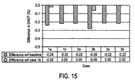
- Fig. 15 illustrates the percentage differences in GAEP with respect to the baseline case and case 1b for the six cases of the example.
- Case 1b is the baseline and is based on the airfoil t/c and the design c l distributions of the prior art Z-48 blade.
- a 0.1% decrease in GAEP in Fig. 1 results to an annual loss of approximately $367 per turbine at $0.05/kWh.
- the baseline case provides a significant amount of energy compared with the other cases.
- the baseline case is the best-case scenario in terms of energy capture but is one of the worst designs from a structural point of view. Therefore, the optimum case is not the baseline case when the objective is to balance structural and aerodynamic requirements.
- the similar GAEP in each of these cases illustrates that the decrease in energy capture from increasing the airfoil t/c is compensated by the increase in GAEP from increasing the design c l .
- FIG. 16 and 18 depicting the corresponding chord and physical thickness distributions, respectively.
- inboard chord lengths are large, which increases the costs of the blades. Consequently, truncating the inboard chord lengths is an attractive option.
- Fig. 18 shows the chord distributions with and without truncation of the inboard chord lengths for cases 1b, 2b and 3b.
- the corresponding distributions for the physical blade thickness are depicted in Fig. 19.
- Tc stands for truncated chords
- Ta stands for truncated airfoils.
- Fig. 19 clearly supports the structural advantage of truncating the airfoil when truncating the chord.
- the subject invention has resulted in a family of airfoils having operational and structural characteristics with substantially enhanced performance capability over prior airfoils used in the same or similar applications.
- the family of airfoils includes thickness-to-chord ratios ranging from 14% to 45%.
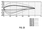
- a composite of all airfoils configured using these criteria is shown in Fig. 23.
- the first airfoils 9914.dat includes a thickness-to-chord ratio of 14% with maximum t/c located near the 30% chord.
- the design lift coefficient is 1.10 to 1.25 at which maximum lift-to-drag occurs.
- the design Reynolds number is 8 million. In performance this airfoil has demonstrated relatively soft stall characteristics.
- the airfoil has relative insensitivity to leading edge surface roughness of the maximum and design lift coefficients. This airfoil may be easily blended with other airfoils in the family of airfoils made in accordance with the subject invention.
- Another airfoils 9918.dat in this family includes a thickness-to-chord ratio of 18% with maximum t/c located near the 30% chord.
- the design lift coefficient is 1.10 to 1.25 at which maximum lift-to-drag occurs.
- the design Reynolds number is 8 million. In performance this airfoil has demonstrated relatively soft stall characteristics.
- the airfoil has relative insensitivity to leading edge surface roughness of the maximum and design lift coefficients. This airfoil may be easily blended with other airfoils in the family of airfoils made in accordance with the subject invention.
- An additional airfoils 9924.dat includes a thickness-to-chord ratio of 24% with maximum t/c located near the 30% chord.
- the design lift coefficient is 1.20 to 1.25 at which maximum lift-to-drag occurs.
- the design Reynolds number is 7 million. In performance this airfoil has demonstrated relatively soft stall characteristics.
- the airfoil has relative insensitivity to leading edge surface roughness of the maximum and design lift coefficients. This airfoil may be easily blended with other airfoils in the family of airfoils made in accordance with the subject invention.
- An additional airfoils 9927.dat includes a thickness-to-chord ratio of 27% with maximum t/c located near the 30% chord.
- the design lift coefficient is 1.20 to 1.30 at which maximum lift-to-drag occurs.
- the design Reynolds number is 5 million. In performance this airfoil has demonstrated relatively soft stall characteristics.
- the airfoil has relative insensitivity to leading edge surface roughness of the maximum and design lift coefficients. This airfoil may be easily blended with other airfoils in the family of airfoils made in accordance with the subject invention.
- An additional airfoils 9930.dat includes a thickness-to-chord ratio of 30% with maximum t/c located near the 20% chord.
- the design lift coefficient is 1.25-1.45 at which maximum lift-to-drag occurs.
- the design Reynolds number is 4 million. In performance this airfoil has demonstrated relatively soft stall characteristics.
- the airfoil has relative insensitivity to leading edge surface roughness of the maximum and design lift coefficients. This airfoil may be easily blended with other airfoils in the family of airfoils made in accordance with the subject invention.
- An additional airfoils 9945.dat includes a thickness-to-chord ratio of 45% with maximum t/c located near the 30% chord.
- the design lift coefficient is 1.25 at which maximum lift-to-drag occurs.
- the design Reynolds number is 3 million. In performance this airfoil has demonstrated relatively soft stall characteristics.
- the airfoil has relative insensitivity to leading edge surface roughness of the maximum and design lift coefficients, This airfoil may be easily blended with other airfoils in the family of airfoils made in accordance with the subject invention.
- the thickest (45%) airfoil may be a truncated airfoil in certain applications.
- the primary airfoil (18%) and the thick tip airfoil (14%) have increased laminar flow. This promotes a softer stall, which is more desirable. It also leads to improved rotor performance.
- Noise was also taken into consideration in the tip airfoil design. It is likely that for an airfoil with high aft loading (large aft underchamber) there will be associated increased unsteadiness in the airfoil wake, creating increased noise.
- the tip airfoil is designed with no aft loading on the trailing edge. The wake is less likely to be unsteady and consequently this will lead to quieter blade operation.
- a preliminary 45% thick airfoil included a 9% trailing edge thickness to further alleviate the strong pressure recovery on the upper surface that is solely a consequence of the high thickness.
- the thinner trailing edge of 1.2% is used in the final design because of manufacturing considerations.
- a feature introduced into these airfoils is the blunt leading edges that should lead to more favorable startup torque when the airfoils operate at or near 90°
Landscapes
- Engineering & Computer Science (AREA)
- Chemical & Material Sciences (AREA)
- Life Sciences & Earth Sciences (AREA)
- Fluid Mechanics (AREA)
- Sustainable Development (AREA)
- Sustainable Energy (AREA)
- Physics & Mathematics (AREA)
- Combustion & Propulsion (AREA)
- Mechanical Engineering (AREA)
- General Engineering & Computer Science (AREA)
- Wind Motors (AREA)
- Structures Of Non-Positive Displacement Pumps (AREA)
- Air-Flow Control Members (AREA)
- Other Liquid Machine Or Engine Such As Wave Power Use (AREA)
Abstract
Description
- The subject invention is generally related to wind power turbines and is specifically directed to a family of airfoil configurations for optimizing the performance of the wind turbine.
- Wind power turbines are well known. The turbine blades or airfoils are one of the primary factors in determining the efficiency of the system and thus are a critical factor in optimizing performance. Typically, the turbine rotor blade design proceeds by first identifying a family of airfoils to be employed and then determining the optimum spanwise distribution of solidity and twist in order to optimize the power coefficient at each spanwise location. This procedure often does not result in the structurally optimal blade for the specific application. Various efforts to optimize the blade configuration have been used over the years, with varying results.
- By way of example, Zond Energy Systems, Inc. (the Assignee of the subject invention) has generally used a thinner airfoil configuration than its European counterparts. For example, the 34 meter blades manufactured by LM Glasfibre for Tacke's 70 meter TW1.5s system employ a 39% thick section at the 25% spanwise location as compared t a 24% thick section on the comparable Zond Z46/48/50 blades. Even at 40% span, the airfoil section is 30% thick. This has a significant impact upon drag, reducing the energy capture from these blades by as much as 10%.
- Turbines currently on the market have rotor loading of approximately 0.42-0.45kW/m2 for machines certified IEC Class 1, 0.38-0.41kW/ m2 for Class 2 and 0.33-0.38kW/m2 for Class 3. Taking a given wind turbine and then scaling both the rotor and drive train, including the generator, in proportion to each other it is a fairly straightforward series of calculations to determine the dependence of blade loads upon rotor size. If it is assumed that the rotor aerodynamics and solidity remain constant as the rotor is scaled, then the rated wind speed will remain constant for the various sized machines. For a turbine such as Zond's 750 kW series, the tip speed of 85 m/s is approximately the higher limit. Using this as a fixed tip speed, in can be determined that the rated shaft speed will scale inversely to the rotor:
- Since the rated power, Prated, scales as the rotor diameter squared for a fixed rotor loading, and since the rated power is a product of the rated torque and the rated shaft speed, it follows that the rated torque scales as the cube of the rotor diameter:Where Fx represents the in-plane forces per unit length.

- The mathematical model for all wind turbine airfoils follows these equations. What remains is to develop a better understanding of these models in order to maximize airfoil design. At present certain aspects of the design are not clearly understood and the resulting airfoil designs of the prior art are less than optimum.
- US 4,976,587 discloses a wind turbine rotor blade including NASA LS(1)-04xx airfoil sections having a twist not greater than 8 degrees and a construction for such a blade which includes not parting line along the leading edge. The bond between a rectangular spar and the outer skin is reinforced by channels of "C"-shaped cross-section fixed to the skin and the spar. Furthermore, US 4,976,587 discloses a method for manufacturing a rotor blade of this construction.
- The book "Windkraftanlagen, ausgeführte Rotorplattformen" from Hau, Erich, Springer Verlag, Berlin XP002174275, page 113 - page 118 discloses some information about the geometry of rotor blades and of their features.
- US 4,519,746 discloses an improved airfoil blade for aircraft propellers and the like which exhibits high aerodynamic performance and low far and near field noise levels at a minimum weight is provided with a high lift and high lift to track cross-sectional airfoil shape characterized by a blunt, generally parabolic leading edge portion which fairs into a pressure surface characterized by a leading convex portion. For thickness ratios less than approximately 0.15, the pressure surface includes a concave trailing portion at one and thereof fairing into the leading convex portion and at the other end thereof, terminating at a blunt trailing edge. The leading edge portion also fairs into a suction surface which is convex along substantially the entire length thereof to the blade trailing edge.
- The document of Tangier at al.: "NREL airfoil families for HAWTs", National Renewable Energy Laboratory Report, XX, XX, page 1-12, XP002928902" deals about the development of special purpose are foils for horizontal axis wind turbines (HAWTs) which began in 1984 as a joined effort between the National Renewable Energy Laboratory (NREL), formally the Solar Energy Research Institute (SERI), and Airfoils, Incorporated. Since at time nine airfoil families have been designed for various size rotors using the eppler airfoil design and analysis code. A general performance requirement of the new airfoil families is that they exhibit a maximum lift coefficient which is relatively insensitive to roughness effects. The airfoil families address the needs of stall-regulated, variable-pitch, and variable-rpm wind turbines. For stall-regulated rotors, a better peak-power control is achieved through the design tip airfoils that restrain the maximum lift coefficient. Restrained maximum lift coefficient allows the use of more swept disk area for a given generator size. Although, for stall-regulated rotors, tip airfoils with high thickness are used to accommodate all the speed control devices. For variable-pitch and variable-rpm rotors, tip airfoils having a high maximum lift coefficient lend themselves to light weight blades with low solidity. Tip airfoils having low thickness result in less track for blades having full span pitch control. Annual energy improvements from the NREL airfoil families are projected to be 23 % to 35 % for stall-regulated turbines, 8 % to 20 % for variable-pitch turbines, and 8 % to 10 % for variable rpm turbines. The improvement for stall-regulated turbines have been verified in field tests.
- US 4,844,698 discloses a propeller having blades designed to achieve maximum threst at lower static velocities in both forward and reverse pitch modes. Each blade has a generous leading edge radius leading to an upper surface having positive camber and a lower surface having positive camber adjacent the leading edge and negative camber adjacent the trailing edge. Each blade also has a high thickness-to-chord ratio and lower span-to-chord ratio or aspect ratio. This thick blade profile and aft loading leads to a more uniform pressure distribution and laminar air flow across the blade surface resulting in a higher coefficient of lift, increased blade life and reliability, and lower noise levels.
- EP 0 675 285 A1 discloses airfoils for the blade of a wind turbine wherein each airfoil is characterized by a thickness in a range from 16 % -24 % and a maximum lift coefficient designed to be largely insensitive to roughness effects. The airfoils include a family of airfoils for a blade 15 to 25 m in length, a family of air foils for a blade 1 to 5 m in length and a family or airfoils for a blade 5 to 10 m in length.
- WO 99/27252 discloses airfoils for the tip regions and mid-span regions of a wind turbine blade which have upper and lower surface shape contours between a leading edge and a trailing edge to minimize roughness effects of the air foils and provide maximum lift coefficients that are largely insensitive to roughness effects. In one embodiment, the air foil has a thickness between about 14 - 17 %, a Reynolds number in the range of about 1,500,000 to 2,000,000, and a maximum lift coefficient in a range of about 1.4 to 1.5. In another embodiment, the airfoil has a thickness between about 14 - 16 %, a Reynolds number in the range of about 1,500,000 to 3,000,000, and a maximum lift coefficient in a range of about 0.7 to 1.5.
- US 5,474,425 discloses horizontal axis, free yaw, self-regulated wind turbines which have strong, light weight, fatigue resistant, fixed pitch, wood/gre blades and exhibit superiour performance a range of wind speeds. The blades are designed by employing defined in-board, mid-span and out-span airfoil profiles and interpolating the profiles between the defined profiles and from the latter to the route and the tip of the blades.
- US 4,773,825 discloses improvements to air propellers in so far as the profile of their blades is concerned. The law of evolution of the curvages of the extrados is the following: the curvager, maximum at the leading edge, increases first of all rapidly to reach a value of about 4 at a point at about 4 % of the length of the chord, and then decreases regularly to reach a substantial zero value at the trailing edge. The law of evolution of the curvages of intrados is the following: the curvager, maximum at the leading edge, decreases first of all rapidly to reach a value of about 8 at about 3,5 % of the length of the chord, then decreases less rapidly to reach a zero value at a point situated between 10 % and 60 % of the length of the chord, decreases further to a slightly negative value and then remains practically constant as far as the trailing edge.
- US 5,252,381 discloses an airfoil section comprising a relative thick trailing edge and a sloped rear surface.
- In view of the above, it is an object of the invention to provide an airfoil design having substantially improved performance characteristics of airfoil designs of prior art.
- This object is achieved bay an airfoil for a power turbine of claim 1 and a family of airfoils of claim 13, whereas advantageous embodiments of the invention are characterized in the sub-claims.
- The combination of aerodynamic optimization and structural optimization in accordance with the teachings of the invention results in a new and novel airfoil design having substantially improved performance characteristics of airfoil designs of the prior art. The aforementioned mathematic modeling yields maximum aerodynamic criteria. This is then coupled with a structural analysis to modify the optimum aerodynamic design into a balance, substantially optimized airfoil configuration. The resulting airfoils of the subject invention have substantial performance impact on GAEP when compared to the airfoils of the prior art. The subject invention is an airfoil design based on the theoretical optimum aerodynamic structure modified as required to maximize structural integrity.
- The subject invention is the result of an effort to maximize and optimize airfoil configuration and design by determining the important characteristics of the mathematical definition of the airfoil consistent with the above prior-art recognized mathematical modeling.
- This procedure provides the criteria for maximizing airfoil performance to achieve highest GAEP while taking into consideration the aerodynamic design parameters as balanced against structural requirements. The methodology of the subject invention permits the design of airfoils of predictable performance while achieving necessary structural integrity.
- As a result of this approach, the subject invention has resulted in a family of airfoils having operational and structural characteristics with substantially enhanced performance capability over prior airfoils used in the same or similar applications. The family of airfoils includes thickness-to-chord ratios ranging from 14% to 45%.
- In accordance with the invention, if the rotors are scaled up proportionately (i.e., the solidity remains constant), then substitution of Equation 2 into Equation 3 results in the conclusion that Fx at any equivalent spanwise location (i.e., r/R) scales as the rotor diameter:
- Since the rotor is being scaled up, the chord, c, also scales as the rotor diameter. Since the rotor loading remains constant, qrated and sinϕ remain constant, it follows from Equations 4 and 5 that C1 remains constant along the blade as they are scaled up. Since none of the flow angles or blade geometry changes other than being scaled up, it follows that the out-of-plane forces per unit length also scale as the rotor diameter:
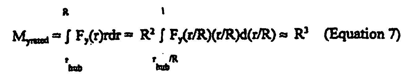
- Therefore, the flapwise blade root bending moment Myrated also scales as the rotor diameter cubed:
- In the subject invention, it has been determined that when the rotor is scaled up in diameter (keeping the solidity constant), while the rated power and tip speed both remain constant, the rated wind speed drops as the rotor diameter increases, according to the well-known relationship:
- Assuming the rated power is constant, this yields:
- This leads to the conclusion that the rated tip speed ration, X, increases with the rotor diameter:
- For a constant tip speed.
- In this instance, Equation 2 becomes:
- Substituting Equation 3 into Equation 11, this yields:
- Which is dramatically different than previously assumed. Looking again at Equation 5, in the methodology of the subject invention the dynamic pressure at outboard station is dominated by the tangential velocity, so the drop in rated wind speed has little effect on the dynamic pressure at rated wind speed. Thus, the inflow angle varies inversely with the local speed ration and Equations 5 and 12 become:
- Substituting Equation 10 for X, combining Equations 12 and 13 yields:
- Fx and Fy represent the values at a given equivalent spanwise location, i.e., the same r/R location on each blade. Now, substituting Equation 15 into Equation 7, the result is:

- In the stated case, the root bending moment scales as the radius to the power 1.66.
- This model was confirmed using Bladed and three rotors for a 750kW turbine. (Bladed is a commercially available design program offered by Garrad Hassan). With a 50m rotor, a 52m rotor and a 55m rotor. The measured scaling factor was in the range of 1.6, or very close to the calculated theoretical scale factor of 1.66 as derived in Equation 15). Realizing that the calculated analysis (Equation 16) ignores a number of secondary effects, e.g., the influence of the changing rated wind speed on the dynamic pressure and other variables, the actual test substantially verifies the calculated analysis. Recognizing that fatigue loads derive from the same aerodynamic model used in the above analysis, which calculates static (extreme) loads, it can be presumed that the fatigue loads will scale similarly as in Equation 16.
- Using the assumption derived from the trade-off studies that halving the blade stiffness (doubling the deflection) results in a 15% reduction in fatigue, then Equation 16 can be used to calculate what size rotor will result in a 15% increase in loads. For example, using a Tackes'sTW1.5s turbine with a 70.5m rotor and a 1,500kW rating it can be determined from the trade-off studies that when the stiffness of the blade is halved that the loads will be reduced 15%. The rotor can then be scaled up in accordance with the following formula, which is derived from Equation 16:
- Thus, the 70.5m rotor could be increased by 10%, to a 77m rotor without increasing the key design fatigue loads if the stiffness is relaxed two-fold. This results in a 20% increase in swept area and, assuming 50% of the energy capture comes from operation below rated, a 10% increase in net annual energy production. This example is for a rotor loading of 0.32 kW/m2 (for IEC Class 2).
- As a result of this analysis, a number of initial rotor optimization studies were undertaken using a 77m root diameter. This resulted in a final sizing analysis wherein a 1.8 MW machine, which is more cost effective, results in a scaling of the rotor diameter to 85m. In the preferred embodiment, a more conservative 80.5m rotor diameter is used.
- As a result of these studies it has been determined that:
- 1. Airfoils up to 30% thick can be used at the first station (25%-30% radius) without significant loss in GAEP (Gross Annual Energy Production).
- 2. To maximize GAEP, the airfoil t/c (thickness) should not exceed 21%, 18% and 14%, for the second (55%-60% radius), third (75%-80% radius) and fourth blade stations (90%-95%), respectively.
- 3. Increasing the design cl increased the GAEP. Over the range of design cl a value of 1.25 was found to be the optimum for all blade stations. A lower design cl in the tip region is beneficial for keeping the blades out of stall.
- 4. The loss in GAEP from increasing the airfoil t/c along the blade can be easily compensated by increasing the design cl. Thicker airfoils can be used without sacrificing energy capture.
-
- These aerodynamic studies have been combined with structural design studies to provide a comprehensive design criteria wherein the thickness and lift range of the airfoils is optimized. For optimum aerodynamic performance, thin airfoils having high lift-to-drag ratios are desired while thick airfoils are favorable for structural reasons. High-lift airfoils yield larger lift-to-drag ratios for a given amount of laminar flow as compared with low-lift airfoils, which increases energy capture. High-lift airfoils also have, however, structural implications. Consequently, a balance between aerodynamic and structural considerations is required for defining the optimum airfoil t/c and lift range for a particular blade.
- Thus, it is desirable to quantify the effects of airfoil thickness (t/c) and lift range on energy capture. A tradeoff study using the 1.63-MW NGT having a 77m rotor was used to quantify this information. The analysis yielded data quantifying the effect of airfoil t/c and lift range on the GAEP for a single blade segment at four different radial positions. Entire blades were then designed for maximum energy capture, using the most promising airfoil t/c and lift range for each of the four selected stations. The effects of truncating the inboard chords of the blades on energy production provided data establishing the impact of minimizing the blade area in the root region. For a given set of airfoils it was found that a reduction in chord yields a decrease in physical thickness that is not desired structurally unless the airfoils are also truncated.
- In the preferred embodiment the blade geometry is designed for maximum annual energy production. In designing each blade segment, the optimum axial inflow of 1/3 and design lift coefficient cl are prescribed and the corresponding chord and twist/pitch are obtained using the inverse design capability of the computer program PROPID (PROPID is a commercially available design program. A selected design cl , which is the cl for which maximum lift-to-drag ratio is achieved, results in the same chord length independently of the airfoil t/c considered. In the example used to confirm this analysis the following design constraints were used:
- Mechanical rated power of 1.8 MW.
- System efficiency of 90%, yielding an electrical rated power of 1.62MW
- Three-bladed, upwind rotor having a diameter of 77m
- Design tip-speed ratio of 7.68, which corresponds to a tip-speed of 80m/s at rated power
- Sea level atmospheric conditions.
- In order to determine the annual energy production on this model, an IEC wind class II (average wind speed of 8.5 m/s at hub height) and a Rayleigh wind speed distribution were considered. No losses were taken into account apart from the 90% system efficiency. The GAEP was computed at 100% availability.
- The design process was carried out on blade segments at four radial stations, namely 25%-30% radius, 55%-60% radius, 75%-80% radius, and 90%-95% radius. The design cl is prescribed to 1.05 and the airfoil thickness is varied for each of the four radial stations. Also, the airfoil thickness at each radial station was fixed and the design cl was varied. For this study on the effects of the design cl on energy capture, the airfoil t/c was fixed at 27% for station 1,21% for station 2 16% for station 3 and 12% for station 4. Entire blade design is also considered with the airfoils used along the blade defined at the same four stations as the segment designs and the hub modeled as a cylinder.
- Out of this study, a baseline case has been developed representing a best-case scenario in terms of maximizing energy capture as it uses higher-lift airfoils than those of the prior art Z-48 blade, while having similar airfoil t/c distribution.
- Out of this it has been determined that airfoils up to 30% thick can be used at the first station (25%-30% radius) without a significant loss in GAEP. Truncating the 30% thick airfoil significantly reduces GAEP with losses up to 12 times greater than that for the non-truncated 30% airfoil. These losses in GAEP from truncating the 30% thick airfoil may be weighted against the structural advantages that truncation provides.
- GAEP is maximized when the airfoil t/c does not exceed 21% 18% and 14%, for the second (55%-60% radius), third (75%-80% radius), and fourth blade stations (90%-95%), respectively.
- Increasing the design cl increases the GAEP. A value of 1.25 has be found to be the optimum for all blade stations although a lower design cl in the tip region might be required depending on the ability of the controller to keep the blades out of stall.
- The loss in GAEP from increasing the airfoil t/c along the blade can be easily compensated by increasing the design cl . Therefore, thicker airfoils than those of the prior art Z-48 blade can be used without sacrificing energy capture.
- Truncating or shortening the inboard chord should be limited to 25%-30% of the maximum nominal chord length value. Such truncation of the chord has only a small effect on the GAEP, particularly if the root airfoil is not truncated.
- Based on this criteria, airfoil design may be optimized using a balance of maximized aerodynamic and maximized structural requirements to provide a dependable, efficient airfoil with enhanced GAEP over prior art configurations.
- It is, therefore, an object and feature of the subject to provide a means and method for designing an enhanced airfoil configuration for a wind turbine maximizing aerodynamic design parameters.
- It is another object and feature of the subject invention to provide a means and method for designing an enhanced airfoil configuration for a wind turbine maximizing structural design parameters.
- It is a further object and feature of the subject invention to provide a means and method for designing an enhanced airfoil configuration with balanced aerodynamic and structural characteristics.
- It is an additional object and feature of the subject invention to provide an airfoil designed with enhanced GAEP capability.
- Other objects and features of the invention will be readily apparent from the accompanying drawings and detailed description of the preferred embodiment.
-
- Fig. is a table showing airfoil thickness for each radial station considered in the segment designs.
- Fig. 2 is a table showing lift coefficient for each radial station of Fig. 1.
- Fig. 3 is a table showing airfoil thickness and design lift coefficient at each station for the full blade designs.
- Fig. 4 is a chart showing gross annual energy production (GAEP) for different airfoil thickness and blade stations.
- Fig. 5 is a graph showing GAEP for different airfoil thickness considered for the first station at 25%-30% radius.
- Fig. 6 is a graph showing GAEP for different airfoil thickness considered for the second station at 55%-60% radius.
- Fig.7 is a graph showing GAEP for different airfoil thickness considered for the third station at 75%-80% radius.
- Fig. 8 is a graph showing GAEP for different airfoil thickness considered for the fourth station at 90%-95% radius.
- Fig. 9 is a chart showing GAEP for different airfoil design lift coefficient and blade stations.
- Fig. 10 is a graph showing GAEP for different design lift coefficients for the first station at 25%-30% radius.
- Fig. 11 is a graph showing GAEP for different design lift coefficients for the first station at 55%-60% radius.
- Fig. 12 is a graph showing GAEP for different design lift coefficients for the first station at 75%-80% radius.
- Fig. 13 is a graph showing GAEP for different design lift coefficients for the first station at 90%-95% radius.
- Fig. 14 is a table showing the maximum loss in yearly income resulting from a difference of 0.4 in the design lift coefficient for one blade segment at the different stations considered.
- Fig. 15 is a table showing the difference in GAEP capture with respect to a baseline case (7,336.7MWh) and case 1b (7,320.6MWh) for the cases without inboard chord truncation.
- Fig. 16 is a diagram showing chord distribution for blade design.
- Fig. 17 is a diagram showing physical thickness distribution for blade design.
- Fig. 18 is a diagram showing chord distributions for the blade designs b, 2b, and 3b with and without truncation.
- Fig. 19 is a diagram showing thickness distribution for the blade designs 1b, 2b and3b with and without truncated airfoils.
- Fig. 20 is a chart showing the difference in GAEP capture with respect to the baseline case (7,336.7 MWh) and case 1b (7,320.6 MWh) for the cases with inboard chord truncation.
- Fig. 21 is a chart showing the difference in GAEP capture with respect to the baseline case (7,336.7 MWh) and case 2b (7,320.6 MWh) with increasing inboard chord for case 2b without airfoil truncation.
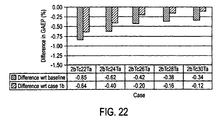
- Fig. 22 is a chart showing the difference in GAEP capture with respect to the baseline case (7,336.7 MWh) and case 2b (7,320.6 MWh) with increasing inboard chord for case 2b with airfoil truncation.
- Fig. 23 is a composite plot of all airfoils to scale with grid.
-
- As described above, the maximum aerodynamic criteria for an optimum airfoil is derived using the formula:where Equation 16 can be used to calculate what size rotor will result in a 15% decrease in loads. For example, using a Tackes'sTW1.5s turbine with a 70.5m rotor and a 1,500kW rating it can be determined from the trade-off studies that when the stiffness of the blade is halved that the loads will be reduced 15%. The rotor can then be scaled up in accordance with the following formula, which is derived from Equation 16:

- Once this is done, then the design is modified by determining the structural characteristics and modifying from the optimized aerodynamic design in accordance the tabular information collected as shown, by way of example, in Figs. 1-13. It should be noted that the examples used for the tabulations shown in Figs. 1-13 are exemplary. The same methodology can be used for other structural configurations. The crux of the invention is the use of this structural data to modify the optimized aerodynamic design in order to balance the structural integrity of the airfoil with the optimum aerodynamics.
- Fig. 1 shows the t/c thickness v\considered for each radial station 1-4. The fifteen cases shown in Fig. 1. The airfoil thickness at each radial station is fixed and the design cl is varied in Fig. 2. In the example for determining the effects of the design cl on energy capture, the airfoil t/c was fixed at 27% for station 1,21% for station 2, 16% for station 3 and 12% for station 4.
- The same methodology is used in connection with the design of entire blades (blade designs), and these results are shown in Fig. 3. A total of seven blade design cases are shown. The airfoils used along the blade are defined at the same four station as the segment designs and the hub is modeled as a cylinder. A cutout speed of 25 m/s is used for computing the GAEP. Fig. 3 shows the airfoil t/c and design cl at each station for the seven blade design cases. The baseline case represents a best-case scenario in terms of maximizing energy capture. The airfoil t/c and design cl distribution of a prior art Z-48 blade are that of case 1 b. Case la shows the departures from the Z-48 blade with increasing airfoil t/c with increasing design cl to counterbalance the reduction in blade chord from the use of high-lift airfoils.
- The effects of truncating or shortening the inboard chord on energy capture are quantified for cases 1 b, 2b and 3b. In truncating the chord, two scenarios are considered. First, the same airfoil t/c is used and thus the physical blade thickness is reduced proportionally to the decrease in chord. Second, the airfoil is truncated the same amount as the chord, thereby keeping the physical blade thickness constant.
- The segment designs are subdivided into two sets of cases. The first set covers a range of airfoil t/c for a given design cl of 1.05, and the second set considered increases in the design cl while fixing the airfoil t/c. The chord length is the same for a given design cl and station while the rotor thrust are the same for a given station independently of the design cl and airfoil t/c.
- Fig. 4 illustrates a comparison between GAEP of all cases shown in Fig. 1. The first station yields about 1/3 the GAEP of the fourth station. In contrast, the second and third stations provide approximately 70% and 93% of the GAEP of the fourth station, respectively. The differences in GAEP for a given station are shown in Figs. 5-8.
- The GAEP results as a function of airfoil t/c for the first station are shown in Fig. 5. The axis for the GAEP represents a 10% difference. The decrease in GAEP with airfoil t/c is relatively small for the non-truncated airfoils, and thus the structural advantages of increasing the airfoil t/c are likely to be beneficial despite the loss in GAEP. Truncating the 30% thick airfoil results in a rapid loss in GAEP. Using $0.05/kWh, the maximum difference in GAEP depicted in Fig. 4 corresponds to a loss in annual income of $416.00, which may be significant considering that this is for a single blade segment. Thus, the loss in GAEP from truncating the 30% thick airfoil should be balanced with the structural advantages that truncation provides.
- Fig. 6 presents the GAEP results for the second station and shows that an airfoil t/c of 24% corresponds to the optimum point (the point of diminishing return). The axis for the GAEP represents a difference of 2%. At $0.05/K\kWh, the maximum difference in annual income is $129.00. Airfoil t/c of 21%-24% are optimum for this station.
- The GAEP results for the third station are depicted in Fig. 7, for which the axis for the GAEP is again a 2% difference. Airfoil t/c of 18% is maximum.
- Fig. 8 shows the GAEP results for the fourth station, with again a GAEP axis scaled for a 2% difference. The maximum airfoil t/c is 14%.
- Fig. 9 represents the GAEP of the twelve cases shown in Fig. 2. The relative differences between the results are similar to those for the variation in airfoil t/c. Figs. 10-13 show the GAEP for each station with a GAEP axis corresponding to a maximum difference of 2%. Fore each station, increasing cl improved the GAEP and a design cl of 1.25 was found to be the point of diminishing return. The trend of increasing GAEP with increasing c, can be traced to the fixed amount of laminar flow of the airfoils.
- Fig 14 shows the difference in annual income for each station assuming a price of $0.05/kWh. The difference is small for the inboard station and thus the merit of increasing the design c, inboard is controlled by the effect of decreasing the chord on the structure. For the outboard stations, the payoff in increasing the design cl is larger.
- The blade designs are summarized in Figs. 15-23. Fig. 15 illustrates the percentage differences in GAEP with respect to the baseline case and case 1b for the six cases of the example. Case 1b is the baseline and is based on the airfoil t/c and the design cl distributions of the prior art Z-48 blade. A 0.1% decrease in GAEP in Fig. 1 results to an annual loss of approximately $367 per turbine at $0.05/kWh. As shown in Fig. 8, the baseline case provides a significant amount of energy compared with the other cases. The baseline case is the best-case scenario in terms of energy capture but is one of the worst designs from a structural point of view. Therefore, the optimum case is not the baseline case when the objective is to balance structural and aerodynamic requirements. The similar GAEP in each of these cases illustrates that the decrease in energy capture from increasing the airfoil t/c is compensated by the increase in GAEP from increasing the design cl.
- An indication of the structural implications of each case is illustrated in Figs. 16 and 18, depicting the corresponding chord and physical thickness distributions, respectively. In all cases, inboard chord lengths are large, which increases the costs of the blades. Consequently, truncating the inboard chord lengths is an attractive option. Fig. 18 shows the chord distributions with and without truncation of the inboard chord lengths for cases 1b, 2b and 3b. The corresponding distributions for the physical blade thickness are depicted in Fig. 19. Tc stands for truncated chords and Ta stands for truncated airfoils. Fig. 19 clearly supports the structural advantage of truncating the airfoil when truncating the chord.
- The effects of truncating the inboard chord to a maximum length of 2.2m (or in this case 10% larger than the hub diameter) in case 1b, 2b and 3b are indicated in Fig. 20. Results for two scenarios are illustrated. In those cases with the extension "Tc22" (maximum chord of 2.2m), the root airfoil was not truncated while those for the cases with the extension "Tc22Ta" used a truncated root airfoil. The extent of the truncation is directly proportional to the reduction in chord length. Cases with a larger extent of truncation have a larger decrease in GAEP, and truncating the airfoils further reduced the GAEP. Reduction from chord truncation results in a decrease in GAEP of $293-$624 at $0.05/kWh. Truncation of the root airfoil in addition to the chord increases the annual loss of GAEP to between $2,055 and $3,707. However, this approach may still be desirable based on the structural implications of the application.
- Smaller amounts of inboard chord truncation for case 2b are shown in Fig. 21, without truncation of the airfoil, and Fig. 22, with truncation of the airfoil. Maximum chord lengths are 2.4m, 2.6m, 2.8m and 3.0m. As shown in Fig 21, the maximum chord length of 2.4m (or approximately 70% of the maximum chord length before truncation is the point of diminishing return. When the root airfoil is truncated, the optimum chord length truncation is to 2.6m see Fig. 22. Note that limiting the chord to 2.6m, the same GAEP as without chord truncation is virtually achieved.
- These tests results provide the criteria for maximizing airfoil performance to achieve highest GAEP while taking into consideration the aerodynamic design parameters as balanced against structural requirements. The methodology of the subject invention permits the design of airfoils of predictable performance while achieving necessary structural integrity.
- As a result of this approach, the subject invention has resulted in a family of airfoils having operational and structural characteristics with substantially enhanced performance capability over prior airfoils used in the same or similar applications. The family of airfoils includes thickness-to-chord ratios ranging from 14% to 45%. A composite of all airfoils configured using these criteria is shown in Fig. 23.
- The first airfoils 9914.dat includes a thickness-to-chord ratio of 14% with maximum t/c located near the 30% chord. The design lift coefficient is 1.10 to 1.25 at which maximum lift-to-drag occurs. The design Reynolds number is 8 million. In performance this airfoil has demonstrated relatively soft stall characteristics. The airfoil has relative insensitivity to leading edge surface roughness of the maximum and design lift coefficients. This airfoil may be easily blended with other airfoils in the family of airfoils made in accordance with the subject invention.
- Another airfoils 9918.dat in this family includes a thickness-to-chord ratio of 18% with maximum t/c located near the 30% chord. The design lift coefficient is 1.10 to 1.25 at which maximum lift-to-drag occurs. The design Reynolds number is 8 million. In performance this airfoil has demonstrated relatively soft stall characteristics. The airfoil has relative insensitivity to leading edge surface roughness of the maximum and design lift coefficients. This airfoil may be easily blended with other airfoils in the family of airfoils made in accordance with the subject invention.
- An additional airfoils 9924.dat includes a thickness-to-chord ratio of 24% with maximum t/c located near the 30% chord. The design lift coefficient is 1.20 to 1.25 at which maximum lift-to-drag occurs. The design Reynolds number is 7 million. In performance this airfoil has demonstrated relatively soft stall characteristics. The airfoil has relative insensitivity to leading edge surface roughness of the maximum and design lift coefficients. This airfoil may be easily blended with other airfoils in the family of airfoils made in accordance with the subject invention.
- An additional airfoils 9927.dat includes a thickness-to-chord ratio of 27% with maximum t/c located near the 30% chord. The design lift coefficient is 1.20 to 1.30 at which maximum lift-to-drag occurs. The design Reynolds number is 5 million. In performance this airfoil has demonstrated relatively soft stall characteristics. The airfoil has relative insensitivity to leading edge surface roughness of the maximum and design lift coefficients. This airfoil may be easily blended with other airfoils in the family of airfoils made in accordance with the subject invention.
- An additional airfoils 9930.dat includes a thickness-to-chord ratio of 30% with maximum t/c located near the 20% chord. The design lift coefficient is 1.25-1.45 at which maximum lift-to-drag occurs. The design Reynolds number is 4 million. In performance this airfoil has demonstrated relatively soft stall characteristics. The airfoil has relative insensitivity to leading edge surface roughness of the maximum and design lift coefficients. This airfoil may be easily blended with other airfoils in the family of airfoils made in accordance with the subject invention.
- An additional airfoils 9945.dat includes a thickness-to-chord ratio of 45% with maximum t/c located near the 30% chord. The design lift coefficient is 1.25 at which maximum lift-to-drag occurs. The design Reynolds number is 3 million. In performance this airfoil has demonstrated relatively soft stall characteristics. The airfoil has relative insensitivity to leading edge surface roughness of the maximum and design lift coefficients, This airfoil may be easily blended with other airfoils in the family of airfoils made in accordance with the subject invention.
- These airfoils form a family capable of being physically blended into a smooth rotor blade surface. The thickest (45%) airfoil may be a truncated airfoil in certain applications. The primary airfoil (18%) and the thick tip airfoil (14%) have increased laminar flow. This promotes a softer stall, which is more desirable. It also leads to improved rotor performance. Noise was also taken into consideration in the tip airfoil design. It is likely that for an airfoil with high aft loading (large aft underchamber) there will be associated increased unsteadiness in the airfoil wake, creating increased noise. Thus the tip airfoil is designed with no aft loading on the trailing edge. The wake is less likely to be unsteady and consequently this will lead to quieter blade operation.
- With respect to the inboard root-region airfoils more weight was given to obtaining satisfactory lift performance rather than low drag. This objective derives from studying the torque contribution for the root region of the blade. For power production, greater emphasis should be placed on lift rather than the lift-to-drag ratio. For such thick airfoils, the challenge was to avoid excessive roughness losses. Two approaches were therefore taken: (1) only a short run of laminar flow was permitted, and (2) the suction surface pressure distributions were not pushed to any limiting extreme. However, to maintain this favorable upper surface pressure distribution and also achieve high lift, the lower surface of the 30% thick airfoil includes considerable underchamber. In the d3esign of the 45% thick airfoil, both the upper surface and lower surface pressure distributions become more extreme, and the performance is further limited as would be expected, especially under rough conditions.
- A preliminary 45% thick airfoil included a 9% trailing edge thickness to further alleviate the strong pressure recovery on the upper surface that is solely a consequence of the high thickness. The thinner trailing edge of 1.2% is used in the final design because of manufacturing considerations. A feature introduced into these airfoils is the blunt leading edges that should lead to more favorable startup torque when the airfoils operate at or near 90°
- While certain features and embodiments of the invention have been described in detail herein it will be understood that the invention includes all improvements, modifications and enhancements within the scope of the following claims.
Claims (14)
- An airfoil for a power wind turbine, the airfoil having a hub, an outer tip and an inboard chord length at the hub, an outboard chord length at the tip and intermediate chord lengths therebetween ranging from 0% to 100% as measured from the hub, and a thickness that is measured as the ratio between the thickness and the cord length at a specific chord location, the airfoil comprising:a. a design lift coefficient in the range of 1.10-1.45, andb. a design Reynolds number in the range of 3 million to 8 million, characterised by a thickness-to-chord ratio in the range of 14% to 45% at approximately the 30% chord.
- The airfoil of claim 1, further including a blunt leading edge.
- The airfoil of claim 1, further including a. truncated inboard chord which is approximately 70% of the chord length before truncation.
- The airfoil of claim 1, further including a truncated inboard chord which is approximately 10% larger than the hub diameter.
- The airfoil of claim 1, wherein a 45% thick airfoil includes an approximately 9% trailing edge thickness.
- The airfoil of claim 1, wherein a 45% thick airfoil includes an approximately 1.2% trailing edge thickness.
- The airfoil of claim 1 comprising:a. a thickness-to-chord ratio in the range of approximately 14% at approximately the 30% chord;b a design lift coefficient in the range of 1.10-1.25; andc. a design Reynolds number of approximately 8 million.
- The airfoil of claim 1 comprising:a. a thickness-to-chord ratio in the range of approximately 18% at approximately the 30% chord;b. a design lift coefficient in the range of 1.10-1.25; andc. a design Reynolds number of approximately 8 million.
- The airfoil of claim 1 comprising:a. a thickness-to-chord ratio in the range of approximately 24% at the approximately 30% chord;b. a design lift coefficient in the range of 1.20 and 1.25; andc. a design Reynolds number of approximately 7 million.
- The airfoil of claim 1 comprising:a. a thickness-to-chord ratio in the range of approximately 27% at the approximately 30% chord;b. a design lift coefficient in the range of 1.20 and 1.30; andc. a design Reynolds number of approximately 5 million.
- The airfoil of claim 1 comprising:a. a thickness-to-chord ratio in the range of approximately 30% at the approximately 30% chord;b. a design lift coefficient in the range of 1.25 and 1.40; andc. a design Reynolds number of approximately 4 million.
- The airfoil of claim 1 comprising:a. a thickness-to-chord ratio in the range of approximately 45% at the approximately 30% chord;b. a design lift coefficient in the range of approximately 1.25; andc. a design Reynolds number of approximately 3 million.
- A family of airfoils for a power wind turbine, comprising:a. a first airfoil as described in claim 1 andb. a last airfoil having a thickness-to-chord ratio of approximately 45% at the approximately 20% chord, a design lift coefficient of approximately 1.25, and a design Reynolds number of approximately 3 million.
- The family of airfoils as called for in claim 13, further including at least one intermediate airfoil between the first and last airfoil, said intermediate airfoil comprising:a. a thickness-to-chord ratio in the range of greater than 14% and less than 45%;b. a design lift coefficient of greater than 1.10 but not exceeding 1.25;c. a design Reynolds number of greater than 3 million but not exceeding 8 million.
Applications Claiming Priority (2)
| Application Number | Priority Date | Filing Date | Title |
|---|---|---|---|
| US561674 | 2000-05-01 | ||
| US09/561,674 US6503058B1 (en) | 2000-05-01 | 2000-05-01 | Air foil configuration for wind turbine |
Publications (2)
| Publication Number | Publication Date |
|---|---|
| EP1152148A1 EP1152148A1 (en) | 2001-11-07 |
| EP1152148B1 true EP1152148B1 (en) | 2005-01-05 |
Family
ID=24242945
Family Applications (1)
| Application Number | Title | Priority Date | Filing Date |
|---|---|---|---|
| EP01110591A Revoked EP1152148B1 (en) | 2000-05-01 | 2001-04-30 | Airfoil profiles for wind turbines |
Country Status (9)
| Country | Link |
|---|---|
| US (1) | US6503058B1 (en) |
| EP (1) | EP1152148B1 (en) |
| CN (1) | CN1280538C (en) |
| AT (1) | ATE286569T1 (en) |
| AU (1) | AU2001261081A1 (en) |
| DE (1) | DE60108195T2 (en) |
| DK (1) | DK1152148T3 (en) |
| ES (1) | ES2237509T3 (en) |
| WO (1) | WO2001083983A1 (en) |
Cited By (6)
| Publication number | Priority date | Publication date | Assignee | Title |
|---|---|---|---|---|
| US7883324B2 (en) | 2007-01-09 | 2011-02-08 | General Electric Company | Wind turbine airfoil family |
| US8226368B2 (en) | 2007-01-09 | 2012-07-24 | General Electric Company | Wind turbine airfoil family |
| AU2009292717B2 (en) * | 2008-09-19 | 2014-10-23 | Wobben Properties Gmbh | Wind turbine with low induction tips |
| EP1856408B1 (en) | 2005-02-22 | 2017-04-05 | Vestas Wind Systems A/S | Wind turbine blade |
| WO2024191285A1 (en) * | 2023-03-10 | 2024-09-19 | Corten Holding Bv | Efficient wind turbine amiable |
| EP3722593B1 (en) * | 2012-03-13 | 2025-10-29 | Wobben Properties GmbH | Twisted blade root |
Families Citing this family (42)
| Publication number | Priority date | Publication date | Assignee | Title |
|---|---|---|---|---|
| US6419464B1 (en) * | 2001-01-16 | 2002-07-16 | Honeywell International Inc. | Vane for variable nozzle turbocharger |
| DE10212467A1 (en) * | 2002-03-20 | 2003-10-09 | Edzard Hafner | Wind power facility for converting wind into energy, has a mast, a rotor with blades, a centralized body, rotary bearings and a geared generator unit. |
| US7357624B2 (en) * | 2002-06-05 | 2008-04-15 | Aloys Wobben | Rotor blade for a wind power plant |
| DE10319246A1 (en) * | 2003-04-28 | 2004-12-16 | Aloys Wobben | Rotor blade of a wind turbine |
| US7086834B2 (en) * | 2004-06-10 | 2006-08-08 | General Electric Company | Methods and apparatus for rotor blade ice detection |
| US7118339B2 (en) | 2004-06-30 | 2006-10-10 | General Electric Company | Methods and apparatus for reduction of asymmetric rotor loads in wind turbines |
| US7095129B2 (en) * | 2004-06-30 | 2006-08-22 | General Electric Company | Methods and apparatus for rotor load control in wind turbines |
| CN1303323C (en) * | 2004-09-16 | 2007-03-07 | 上海交通大学 | Water turbine wingsection for ocean current generation |
| US7344360B2 (en) | 2004-09-29 | 2008-03-18 | General Electric Company | Wind turbine rotor blade with in-plane sweep and devices using same, and methods for making same |
| US8128376B2 (en) * | 2005-08-15 | 2012-03-06 | Abe Karem | High performance outboard section for rotor blades |
| TW200726908A (en) * | 2005-10-04 | 2007-07-16 | Arthur Benjamin O Connor | Wind turbine |
| AU2013224674B2 (en) * | 2006-04-02 | 2016-11-24 | Wobben Properties Gmbh | Wind turbine with slender blade |
| DK3617496T3 (en) | 2006-04-02 | 2024-12-02 | Wobben Properties Gmbh | Wind turbine with thin blade |
| AU2007336537B2 (en) * | 2006-12-22 | 2011-05-26 | Vestas Wind Systems A/S | Wind turbine with rotor blades equipped with winglets and blades for such rotor |
| EP1978245A1 (en) * | 2007-04-04 | 2008-10-08 | Siemens Aktiengesellschaft | Optimised layout for wind turbine rotor blades |
| ES2320962B1 (en) * | 2007-11-28 | 2010-03-11 | GAMESA INNOVATION & TECHNOLOGY S.L. | AERODYNAMIC PROFILE FOR THE ROOT OF AN AIRWOOD SHOVEL WITH DOUBLE ATTACK EDGE. |
| WO2010028441A1 (en) * | 2008-09-11 | 2010-03-18 | Hunter Pacific International Pty Ltd | Extraction fan and rotor |
| JP5371087B2 (en) * | 2008-12-03 | 2013-12-18 | 国立大学法人 東京大学 | Wind generator blade |
| EP2253835A1 (en) * | 2009-05-18 | 2010-11-24 | Lm Glasfiber A/S | Wind turbine blade with base part having non-positive camber |
| EP2275671A1 (en) * | 2009-06-04 | 2011-01-19 | Technical University of Denmark | System and method for designing airfoils |
| WO2010136357A2 (en) * | 2009-05-25 | 2010-12-02 | Chongqing University | Airfoils and method for designing airfoils |
| US8241000B2 (en) * | 2009-06-16 | 2012-08-14 | Heartland Energy Solutions, LLC. | Wind turbine rotor blade and airfoil section |
| US20120207610A1 (en) * | 2009-11-03 | 2012-08-16 | Sepstar, Inc. | Wind turbine blade |
| EP3118449A1 (en) | 2010-04-19 | 2017-01-18 | Wobben Properties GmbH | Method for operating a wind turbine |
| EP2593670B1 (en) | 2010-07-16 | 2017-01-04 | LM WP Patent Holding A/S | Wind turbine blade with narrow shoulder and relatively thick airfoil profiles |
| JP5479300B2 (en) * | 2010-10-22 | 2014-04-23 | 三菱重工業株式会社 | Wind turbine blade, wind power generator equipped with the wind turbine blade, and wind turbine blade design method |
| WO2012053602A1 (en) | 2010-10-22 | 2012-04-26 | 三菱重工業株式会社 | Wind turbine, wind power generation device provided therewith, and wind turbine design method |
| EP2492496B1 (en) * | 2011-02-25 | 2016-06-08 | Nordex Energy GmbH | Wind energy assembly rotor blade with varying blade depth |
| JP5479388B2 (en) | 2011-02-28 | 2014-04-23 | 三菱重工業株式会社 | Wind turbine blade and wind power generator equipped with the same |
| DE102011077129A1 (en) | 2011-06-07 | 2012-12-13 | Aloys Wobben | Method for operating a wind energy plant |
| CN102705173B (en) * | 2012-02-07 | 2014-04-23 | 深圳市艾飞盛风能科技有限公司 | Wind generator and blades thereof |
| US10443562B2 (en) * | 2013-09-02 | 2019-10-15 | Wobben Properties Gmbh | Vortex generator for a wind turbine |
| JP6167051B2 (en) | 2014-02-21 | 2017-07-19 | 三菱重工業株式会社 | Wind turbine blade, wind turbine rotor and wind power generator |
| EP3218599A1 (en) * | 2014-09-09 | 2017-09-20 | Howard Harrison | Optimized multiple airfoil wind turbine blade assembly |
| US9845684B2 (en) * | 2014-11-25 | 2017-12-19 | Pratt & Whitney Canada Corp. | Airfoil with stepped spanwise thickness distribution |
| DE102017124861A1 (en) | 2017-10-24 | 2019-04-25 | Wobben Properties Gmbh | Rotor blade of a wind turbine and method for its design |
| US20200088161A1 (en) * | 2018-09-17 | 2020-03-19 | General Electric Company | Wind Turbine Rotor Blade Assembly for Reduced Noise |
| US11781522B2 (en) | 2018-09-17 | 2023-10-10 | General Electric Company | Wind turbine rotor blade assembly for reduced noise |
| CN110206754B (en) * | 2019-05-21 | 2020-12-01 | 厦门唯科健康产业有限公司 | Design method of volute-free centrifugal wind wheel |
| CN111639404B (en) * | 2020-05-28 | 2024-01-23 | 中国科学院工程热物理研究所 | Optimization method, device and electronic equipment of bionic noise reduction airfoil with serrated trailing edge |
| CN111950083B (en) * | 2020-08-11 | 2022-08-23 | 北京航空航天大学 | Evaluation method and calculation equipment for influence of thickness-chord ratio on airfoil lift characteristic |
| CN119878420B (en) * | 2025-02-27 | 2025-10-21 | 昆明理工大学 | A bionic blade structure for suppressing hydrofoil cavitation |
Family Cites Families (8)
| Publication number | Priority date | Publication date | Assignee | Title |
|---|---|---|---|---|
| US4519746A (en) * | 1981-07-24 | 1985-05-28 | United Technologies Corporation | Airfoil blade |
| FR2590229B1 (en) * | 1985-11-19 | 1988-01-29 | Onera (Off Nat Aerospatiale) | IMPROVEMENTS ON AIR PROPELLERS WITH REGARD TO THE PROFILE OF THEIR BLADES |
| US4844698A (en) * | 1986-06-17 | 1989-07-04 | Imc Magnetics Corp. | Propeller blade |
| US4976587A (en) * | 1988-07-20 | 1990-12-11 | Dwr Wind Technologies Inc. | Composite wind turbine rotor blade and method for making same |
| IL105107A (en) * | 1992-03-18 | 1996-06-18 | Advanced Wind Turbines Inc | Wind turbines |
| US5252381A (en) * | 1992-06-18 | 1993-10-12 | Adler Alan John | Airfoil with thick trailing edge |
| US5562420A (en) * | 1994-03-14 | 1996-10-08 | Midwest Research Institute | Airfoils for wind turbine |
| US6068446A (en) * | 1997-11-20 | 2000-05-30 | Midwest Research Institute | Airfoils for wind turbine |
-
2000
- 2000-05-01 US US09/561,674 patent/US6503058B1/en not_active Expired - Lifetime
-
2001
- 2001-04-27 CN CNB018099033A patent/CN1280538C/en not_active Expired - Lifetime
- 2001-04-27 WO PCT/US2001/013836 patent/WO2001083983A1/en not_active Ceased
- 2001-04-27 AU AU2001261081A patent/AU2001261081A1/en not_active Abandoned
- 2001-04-30 DE DE60108195T patent/DE60108195T2/en not_active Revoked
- 2001-04-30 EP EP01110591A patent/EP1152148B1/en not_active Revoked
- 2001-04-30 ES ES01110591T patent/ES2237509T3/en not_active Expired - Lifetime
- 2001-04-30 DK DK01110591T patent/DK1152148T3/en active
- 2001-04-30 AT AT01110591T patent/ATE286569T1/en not_active IP Right Cessation
Cited By (9)
| Publication number | Priority date | Publication date | Assignee | Title |
|---|---|---|---|---|
| EP1856408B1 (en) | 2005-02-22 | 2017-04-05 | Vestas Wind Systems A/S | Wind turbine blade |
| EP2317125B1 (en) * | 2005-02-22 | 2021-04-28 | Vestas Wind Systems A/S | Wind turbine and blade therefor |
| US7883324B2 (en) | 2007-01-09 | 2011-02-08 | General Electric Company | Wind turbine airfoil family |
| US8226368B2 (en) | 2007-01-09 | 2012-07-24 | General Electric Company | Wind turbine airfoil family |
| AU2009292717B2 (en) * | 2008-09-19 | 2014-10-23 | Wobben Properties Gmbh | Wind turbine with low induction tips |
| EP3722593B1 (en) * | 2012-03-13 | 2025-10-29 | Wobben Properties GmbH | Twisted blade root |
| WO2024191285A1 (en) * | 2023-03-10 | 2024-09-19 | Corten Holding Bv | Efficient wind turbine amiable |
| WO2024191286A1 (en) * | 2023-03-10 | 2024-09-19 | Corten Holding Bv | Large wind turbine amiable |
| WO2024191284A1 (en) * | 2023-03-10 | 2024-09-19 | Corten Holding Bv | Wind turbine amiable |
Also Published As
| Publication number | Publication date |
|---|---|
| ES2237509T3 (en) | 2005-08-01 |
| DK1152148T3 (en) | 2005-05-17 |
| AU2001261081A1 (en) | 2001-11-12 |
| CN1441876A (en) | 2003-09-10 |
| DE60108195D1 (en) | 2005-02-10 |
| EP1152148A1 (en) | 2001-11-07 |
| US6503058B1 (en) | 2003-01-07 |
| CN1280538C (en) | 2006-10-18 |
| DE60108195T2 (en) | 2006-05-11 |
| WO2001083983A1 (en) | 2001-11-08 |
| ATE286569T1 (en) | 2005-01-15 |
Similar Documents
| Publication | Publication Date | Title |
|---|---|---|
| US6503058B1 (en) | Air foil configuration for wind turbine | |
| US8529211B2 (en) | Wind turbine rotor blade and airfoil section | |
| US7393177B2 (en) | Vertical axis wind turbine with optimized blade profile | |
| EP2834517B1 (en) | Twisted blade root | |
| Schubel et al. | Wind turbine blade design review | |
| CN103244348B (en) | Speed-changing oar-changing power curves of wind-driven generator sets optimization method | |
| EP2682597B1 (en) | Method for designing a wind turbine blade comprising a winglet | |
| EP2682602B1 (en) | Wind turbine blade and wind-powered electricity generator provided with same | |
| EP2141355A2 (en) | Wind turbine blades with multiple curvatures | |
| USH2057H1 (en) | Load attenuating passively adaptive wind turbine blade | |
| US20090123289A1 (en) | Quiet Airfoils For Small and Large Wind Turbines | |
| US11428206B2 (en) | Aerofoil tip structure, particularly for a HAWT rotor blade | |
| CN102187092B (en) | Wind turbines with low intake tips | |
| CN101660486A (en) | Wind turbine blades with cross webs | |
| KR20130069812A (en) | Wind turbine blade, wind power generating device comprising same, and wind turbine blade design method | |
| KR101454258B1 (en) | 25% Thickness Airfoil for Large Scale Wind Turbine Blade | |
| Toumi et al. | Aerodynamic analysis of HAWT using Blade Element Method and Q-Blade software | |
| KR101963612B1 (en) | A blade for the active pitch control system of Wind turbine | |
| Cheney et al. | Feasibility study of pultruded blades for wind turbine rotors | |
| KR101454260B1 (en) | 35% Thickness Airfoil for Large Scale Wind Turbine Blade | |
| KR101454259B1 (en) | 30% Thickness Airfoil for Large Scale Wind Turbine Blade | |
| KR101454257B1 (en) | 21% Thickness Airfoil for Large Scale Wind Turbine Blade | |
| KR101454261B1 (en) | 40% Thickness Airfoil for Large Scale Wind Turbine Blade | |
| KR20240126100A (en) | 18% Thickness Airfoil for Large Scale Wind Turbine Blade with Insensitive to Surface Roughness | |
| Thuné et al. | Investigation Of Different Airfoils on Outer Sections of Large Rotor Blades |
Legal Events
| Date | Code | Title | Description |
|---|---|---|---|
| PUAI | Public reference made under article 153(3) epc to a published international application that has entered the european phase |
Free format text: ORIGINAL CODE: 0009012 |
|
| AK | Designated contracting states |
Kind code of ref document: A1 Designated state(s): AT BE CH CY DE DK ES FI FR GB GR IE IT LI LU MC NL PT SE TR |
|
| AX | Request for extension of the european patent |
Free format text: AL;LT;LV;MK;RO;SI |
|
| 17P | Request for examination filed |
Effective date: 20020507 |
|
| AKX | Designation fees paid |
Free format text: AT BE CH CY DE DK ES FI FR GB GR IE IT LI LU MC NL PT SE TR |
|
| RAP1 | Party data changed (applicant data changed or rights of an application transferred) |
Owner name: GENERAL ELECTRIC COMPANY |
|
| 17Q | First examination report despatched |
Effective date: 20021220 |
|
| GRAP | Despatch of communication of intention to grant a patent |
Free format text: ORIGINAL CODE: EPIDOSNIGR1 |
|
| GRAS | Grant fee paid |
Free format text: ORIGINAL CODE: EPIDOSNIGR3 |
|
| GRAA | (expected) grant |
Free format text: ORIGINAL CODE: 0009210 |
|
| AK | Designated contracting states |
Kind code of ref document: B1 Designated state(s): AT BE CH CY DE DK ES FI FR GB GR IE IT LI LU MC NL PT SE TR |
|
| PG25 | Lapsed in a contracting state [announced via postgrant information from national office to epo] |
Ref country code: FR Free format text: LAPSE BECAUSE OF NON-PAYMENT OF DUE FEES Effective date: 20050105 Ref country code: AT Free format text: LAPSE BECAUSE OF FAILURE TO SUBMIT A TRANSLATION OF THE DESCRIPTION OR TO PAY THE FEE WITHIN THE PRESCRIBED TIME-LIMIT Effective date: 20050105 Ref country code: CH Free format text: LAPSE BECAUSE OF FAILURE TO SUBMIT A TRANSLATION OF THE DESCRIPTION OR TO PAY THE FEE WITHIN THE PRESCRIBED TIME-LIMIT Effective date: 20050105 Ref country code: NL Free format text: LAPSE BECAUSE OF FAILURE TO SUBMIT A TRANSLATION OF THE DESCRIPTION OR TO PAY THE FEE WITHIN THE PRESCRIBED TIME-LIMIT Effective date: 20050105 Ref country code: FI Free format text: LAPSE BECAUSE OF FAILURE TO SUBMIT A TRANSLATION OF THE DESCRIPTION OR TO PAY THE FEE WITHIN THE PRESCRIBED TIME-LIMIT Effective date: 20050105 Ref country code: TR Free format text: LAPSE BECAUSE OF FAILURE TO SUBMIT A TRANSLATION OF THE DESCRIPTION OR TO PAY THE FEE WITHIN THE PRESCRIBED TIME-LIMIT Effective date: 20050105 Ref country code: BE Free format text: LAPSE BECAUSE OF FAILURE TO SUBMIT A TRANSLATION OF THE DESCRIPTION OR TO PAY THE FEE WITHIN THE PRESCRIBED TIME-LIMIT Effective date: 20050105 Ref country code: LI Free format text: LAPSE BECAUSE OF FAILURE TO SUBMIT A TRANSLATION OF THE DESCRIPTION OR TO PAY THE FEE WITHIN THE PRESCRIBED TIME-LIMIT Effective date: 20050105 Ref country code: IT Free format text: LAPSE BECAUSE OF FAILURE TO SUBMIT A TRANSLATION OF THE DESCRIPTION OR TO PAY THE FEE WITHIN THE PRESCRIBED TIME-LIMIT;WARNING: LAPSES OF ITALIAN PATENTS WITH EFFECTIVE DATE BEFORE 2007 MAY HAVE OCCURRED AT ANY TIME BEFORE 2007. THE CORRECT EFFECTIVE DATE MAY BE DIFFERENT FROM THE ONE RECORDED. Effective date: 20050105 |
|
| REG | Reference to a national code |
Ref country code: GB Ref legal event code: FG4D |
|
| REG | Reference to a national code |
Ref country code: CH Ref legal event code: EP |
|
| REG | Reference to a national code |
Ref country code: IE Ref legal event code: FG4D |
|
| REF | Corresponds to: |
Ref document number: 60108195 Country of ref document: DE Date of ref document: 20050210 Kind code of ref document: P |
|
| PG25 | Lapsed in a contracting state [announced via postgrant information from national office to epo] |
Ref country code: GR Free format text: LAPSE BECAUSE OF FAILURE TO SUBMIT A TRANSLATION OF THE DESCRIPTION OR TO PAY THE FEE WITHIN THE PRESCRIBED TIME-LIMIT Effective date: 20050405 Ref country code: SE Free format text: LAPSE BECAUSE OF FAILURE TO SUBMIT A TRANSLATION OF THE DESCRIPTION OR TO PAY THE FEE WITHIN THE PRESCRIBED TIME-LIMIT Effective date: 20050405 |
|
| PG25 | Lapsed in a contracting state [announced via postgrant information from national office to epo] |
Ref country code: CY Free format text: LAPSE BECAUSE OF FAILURE TO SUBMIT A TRANSLATION OF THE DESCRIPTION OR TO PAY THE FEE WITHIN THE PRESCRIBED TIME-LIMIT Effective date: 20050430 Ref country code: LU Free format text: LAPSE BECAUSE OF NON-PAYMENT OF DUE FEES Effective date: 20050430 Ref country code: MC Free format text: LAPSE BECAUSE OF NON-PAYMENT OF DUE FEES Effective date: 20050430 Ref country code: GB Free format text: LAPSE BECAUSE OF NON-PAYMENT OF DUE FEES Effective date: 20050430 |
|
| PG25 | Lapsed in a contracting state [announced via postgrant information from national office to epo] |
Ref country code: IE Free format text: LAPSE BECAUSE OF NON-PAYMENT OF DUE FEES Effective date: 20050503 |
|
| REG | Reference to a national code |
Ref country code: DK Ref legal event code: T3 |
|
| NLV1 | Nl: lapsed or annulled due to failure to fulfill the requirements of art. 29p and 29m of the patents act | ||
| REG | Reference to a national code |
Ref country code: CH Ref legal event code: PL |
|
| REG | Reference to a national code |
Ref country code: ES Ref legal event code: FG2A Ref document number: 2237509 Country of ref document: ES Kind code of ref document: T3 |
|
| PLBI | Opposition filed |
Free format text: ORIGINAL CODE: 0009260 |
|
| PLBI | Opposition filed |
Free format text: ORIGINAL CODE: 0009260 |
|
| PLAX | Notice of opposition and request to file observation + time limit sent |
Free format text: ORIGINAL CODE: EPIDOSNOBS2 |
|
| 26 | Opposition filed |
Opponent name: REPOWER SYSTEMS AG Effective date: 20051005 |
|
| 26 | Opposition filed |
Opponent name: REPOWER SYSTEMS AG Effective date: 20051005 Opponent name: VESTAS WIND SYSTEMS A/S Effective date: 20051005 |
|
| GBPC | Gb: european patent ceased through non-payment of renewal fee |
Effective date: 20050430 |
|
| REG | Reference to a national code |
Ref country code: GB Ref legal event code: FG4D |
|
| REG | Reference to a national code |
Ref country code: IE Ref legal event code: MM4A |
|
| EN | Fr: translation not filed | ||
| PLAF | Information modified related to communication of a notice of opposition and request to file observations + time limit |
Free format text: ORIGINAL CODE: EPIDOSCOBS2 |
|
| PLBB | Reply of patent proprietor to notice(s) of opposition received |
Free format text: ORIGINAL CODE: EPIDOSNOBS3 |
|
| PLAB | Opposition data, opponent's data or that of the opponent's representative modified |
Free format text: ORIGINAL CODE: 0009299OPPO |
|
| R26 | Opposition filed (corrected) |
Opponent name: VESTAS WIND SYSTEMS A/S Effective date: 20051005 Opponent name: REPOWER SYSTEMS AG Effective date: 20051005 |
|
| PG25 | Lapsed in a contracting state [announced via postgrant information from national office to epo] |
Ref country code: PT Free format text: LAPSE BECAUSE OF NON-PAYMENT OF DUE FEES Effective date: 20050605 |
|
| PLAB | Opposition data, opponent's data or that of the opponent's representative modified |
Free format text: ORIGINAL CODE: 0009299OPPO |
|
| R26 | Opposition filed (corrected) |
Opponent name: VESTAS WIND SYSTEMS A/S Effective date: 20051005 Opponent name: REPOWER SYSTEMS AG Effective date: 20051005 |
|
| PLAB | Opposition data, opponent's data or that of the opponent's representative modified |
Free format text: ORIGINAL CODE: 0009299OPPO |
|
| R26 | Opposition filed (corrected) |
Opponent name: REPOWER SYSTEMS AG Effective date: 20051005 Opponent name: VESTAS WIND SYSTEMS A/S Effective date: 20051005 |
|
| PGFP | Annual fee paid to national office [announced via postgrant information from national office to epo] |
Ref country code: DE Payment date: 20100428 Year of fee payment: 10 |
|
| RDAF | Communication despatched that patent is revoked |
Free format text: ORIGINAL CODE: EPIDOSNREV1 |
|
| RDAG | Patent revoked |
Free format text: ORIGINAL CODE: 0009271 |
|
| STAA | Information on the status of an ep patent application or granted ep patent |
Free format text: STATUS: PATENT REVOKED |
|
| 27W | Patent revoked |
Effective date: 20100126 |
|
| PGFP | Annual fee paid to national office [announced via postgrant information from national office to epo] |
Ref country code: ES Payment date: 20110426 Year of fee payment: 11 |
|
| PGFP | Annual fee paid to national office [announced via postgrant information from national office to epo] |
Ref country code: DK Payment date: 20110429 Year of fee payment: 11 |