EP1152136A1 - Dispositif et procédé de détection de la dégradation d'un convertisseur catalytique - Google Patents
Dispositif et procédé de détection de la dégradation d'un convertisseur catalytique Download PDFInfo
- Publication number
- EP1152136A1 EP1152136A1 EP01401058A EP01401058A EP1152136A1 EP 1152136 A1 EP1152136 A1 EP 1152136A1 EP 01401058 A EP01401058 A EP 01401058A EP 01401058 A EP01401058 A EP 01401058A EP 1152136 A1 EP1152136 A1 EP 1152136A1
- Authority
- EP
- European Patent Office
- Prior art keywords
- signal
- filtering
- degradation
- engine
- average
- Prior art date
- Legal status (The legal status is an assumption and is not a legal conclusion. Google has not performed a legal analysis and makes no representation as to the accuracy of the status listed.)
- Granted
Links
Images
Classifications
-
- F—MECHANICAL ENGINEERING; LIGHTING; HEATING; WEAPONS; BLASTING
- F01—MACHINES OR ENGINES IN GENERAL; ENGINE PLANTS IN GENERAL; STEAM ENGINES
- F01N—GAS-FLOW SILENCERS OR EXHAUST APPARATUS FOR MACHINES OR ENGINES IN GENERAL; GAS-FLOW SILENCERS OR EXHAUST APPARATUS FOR INTERNAL-COMBUSTION ENGINES
- F01N11/00—Monitoring or diagnostic devices for exhaust-gas treatment apparatus
- F01N11/007—Monitoring or diagnostic devices for exhaust-gas treatment apparatus the diagnostic devices measuring oxygen or air concentration downstream of the exhaust apparatus
-
- F—MECHANICAL ENGINEERING; LIGHTING; HEATING; WEAPONS; BLASTING
- F01—MACHINES OR ENGINES IN GENERAL; ENGINE PLANTS IN GENERAL; STEAM ENGINES
- F01N—GAS-FLOW SILENCERS OR EXHAUST APPARATUS FOR MACHINES OR ENGINES IN GENERAL; GAS-FLOW SILENCERS OR EXHAUST APPARATUS FOR INTERNAL-COMBUSTION ENGINES
- F01N2550/00—Monitoring or diagnosing the deterioration of exhaust systems
- F01N2550/02—Catalytic activity of catalytic converters
-
- F—MECHANICAL ENGINEERING; LIGHTING; HEATING; WEAPONS; BLASTING
- F01—MACHINES OR ENGINES IN GENERAL; ENGINE PLANTS IN GENERAL; STEAM ENGINES
- F01N—GAS-FLOW SILENCERS OR EXHAUST APPARATUS FOR MACHINES OR ENGINES IN GENERAL; GAS-FLOW SILENCERS OR EXHAUST APPARATUS FOR INTERNAL-COMBUSTION ENGINES
- F01N2900/00—Details of electrical control or of the monitoring of the exhaust gas treating apparatus
- F01N2900/04—Methods of control or diagnosing
- F01N2900/0422—Methods of control or diagnosing measuring the elapsed time
-
- Y—GENERAL TAGGING OF NEW TECHNOLOGICAL DEVELOPMENTS; GENERAL TAGGING OF CROSS-SECTIONAL TECHNOLOGIES SPANNING OVER SEVERAL SECTIONS OF THE IPC; TECHNICAL SUBJECTS COVERED BY FORMER USPC CROSS-REFERENCE ART COLLECTIONS [XRACs] AND DIGESTS
- Y02—TECHNOLOGIES OR APPLICATIONS FOR MITIGATION OR ADAPTATION AGAINST CLIMATE CHANGE
- Y02T—CLIMATE CHANGE MITIGATION TECHNOLOGIES RELATED TO TRANSPORTATION
- Y02T10/00—Road transport of goods or passengers
- Y02T10/10—Internal combustion engine [ICE] based vehicles
- Y02T10/12—Improving ICE efficiencies
-
- Y—GENERAL TAGGING OF NEW TECHNOLOGICAL DEVELOPMENTS; GENERAL TAGGING OF CROSS-SECTIONAL TECHNOLOGIES SPANNING OVER SEVERAL SECTIONS OF THE IPC; TECHNICAL SUBJECTS COVERED BY FORMER USPC CROSS-REFERENCE ART COLLECTIONS [XRACs] AND DIGESTS
- Y02—TECHNOLOGIES OR APPLICATIONS FOR MITIGATION OR ADAPTATION AGAINST CLIMATE CHANGE
- Y02T—CLIMATE CHANGE MITIGATION TECHNOLOGIES RELATED TO TRANSPORTATION
- Y02T10/00—Road transport of goods or passengers
- Y02T10/10—Internal combustion engine [ICE] based vehicles
- Y02T10/40—Engine management systems
Definitions
- the present invention relates to the detection of the degradation of a converter three-way catalytic converter on the exhaust system of a combustion engine internal provided so that the combustion chambers receive a homogeneous mixture.
- the invention applies in particular to spark ignition engines operating at gasoline or liquefied petroleum gas, carburetor or injection into the manifold of admission.
- a three-way catalytic converter is used to reduce the gas content exhaust in nitrogen oxides NOx, carbon monoxide CO and hydrocarbons unburnt. Such a three-way converter retains oxygen from the reduction nitrogen oxide and simultaneously uses the retained oxygen to oxidize the hydrocarbons and nitric oxide. The gradual degradation of the catalyst is reflected in particular by the reduction of its capacity to retain oxygen.
- Catalyst performance monitoring devices have already been proposed using a comparison between the output signals provided by two sensors not proportional placed one upstream and the other downstream of the catalytic converter on the path of the exhaust gases. These sensors can in particular be probes lambda whose output voltage increases suddenly when the wealth increases and exceeds a threshold near 98% of the stoichiometry.
- the use of a device diagnosing from the output voltages of two probes have drawbacks.
- the volume of calculation to be performed is important.
- the probes have, due to dispersions during manufacturing, laws of variation of the signal according to the different richness.
- the probes, placed in different conditions, may evolve differently.
- the present invention aims in particular to provide a device and a method for degradation detection responding better than those previously known to requirements of the practice, in particular by removing or at least mitigating the disadvantages above, using only the output signal of a sensor placed downstream of the converter.
- the upstream sensor serves as a reference for the downstream sensor.
- the invention starts from the observation that one can estimate the effectiveness of a catalytic converter by analyzing the signal characteristics of the downstream sensor alone, provided that the signal supplied by the downstream probe is only taken into account in certain operating conditions, notably excluding full operation charge.
- the invention therefore proposes a device for detecting degradation.
- a catalytic converter comprising a non-proportional sensor placed downstream the converter on the exhaust gas path, signal filtering means sensor output eliminating the DC component of the signal, means for supply of a sliding average of the signal filtered by integration and division, means for comparing said average with a threshold and means for inhibiting the means of providing the average and the means of comparison during the full engine load.
- the filtering means will consist of a bandpass filter having a bandwidth at mid-height of between 0.9 and 4 Hertz approximately, capable of be adjustable.
- the 4 Hertz limit corresponds to the response limit of most catalysts in their correct working condition.
- Band limitation passing at 4 Hertz eliminates most of the original disturbances electromagnetic or from parasitic mixing reactions in the collector exhaust during puffs from the combustion chambers. led to choose slightly different values, depending on the type of engine and the type of the catalyst.
- the device can be constituted by an independent assembly, comprising clean circuits to perform filtering and averaging, in the form analog or digital. But in most cases, all of the calculations necessary will be done in digital form, by placing a sampler at analog-to-digital converter between the sensor and the input of a calculation unit, which can be the engine control computer regulating in particular the injection of combustible.
- a calculation unit which can be the engine control computer regulating in particular the injection of combustible.
- the means providing an average give a signal representative of the average power over a determined period of time, integration providing energy corresponding to several successive samples. In general, we will use a integration time of the order of 3 seconds + or -1 second.
- the device comprises two branches of averaging and comparison with a threshold.
- One of these branches is put implemented during idling, and the other during steady operation established out of idle.
- the sliding average calculations will be advantageously done over different periods, for example from 4 seconds to idle and 2.5 to 3 seconds without idle.
- the means of inhibition generally constituted by the engine control computer, will interrupt operation under conditions of determined operation, detected from signals representative of speed and its variations, richness (greater than 1 at full load), slow motion, temperature, and engine brake operation.
- the invention also provides a method for detecting degradation according to which, apart from full load, subjects the signal from a probe to non proportional oxygen placed downstream of the catalyst for sampling and digitization, the digitized samples are subjected to active bandpass filtering eliminating the DC component of the signal, a sliding average of the signal strength filtered by integration and division, and we compare the average to a threshold.
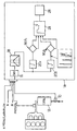
- the device shown in figure 1 uses as output signal the output voltage a sensor 10, which will generally be a lambda probe, placed at the outlet of the catalytic converter 12 of an engine.
- This output signal is generally used by the engine control computer 14 to participate in the preparation of the setpoint amount of fuel to inject.
- This instruction also takes into account other parameters and especially the angle ⁇ of opening of the air throttle valve, the engine speed N and the temperature ⁇ .
- the quantity injected setpoint is provided on an output S.
- the device is shown in Figure 1 in the form of successive blocks mostly corresponding to calculation operations. But in practice, the calculation operations will be performed not by discrete components, but by the engine control computer 14.
- the output signal from sensor 10 is subjected to analog-to-digital conversion in 16, by sampling and digitization.
- analog-to-digital conversion in 16
- sampling and digitization In general, we will use a cadence constant sampling, for example 15.6 Hz.
- the digitized signal for example on 10 bits, is applied to means of filtering 18 making it possible to isolate the significant part of the signal.
- filtering 18 makes it possible to isolate the significant part of the signal.
- the filtering means 18 supply two branches, only one of which is activated at both by the engine control computer 14. Each branch includes means sliding average calculation, by integration over a fixed period and division by the number of samples on which the average was taken.
- Means 20a of a first branch are activated during periods of operation outside full load and without idling.
- the means 20b of the second branch are activated during idling.
- the means 20a for example perform an average over a period of 2.5 to 3 seconds while the means 20b provide a averaged over 4 seconds to account for the least number of cycles engine.
- the output signals of the means 20a and 20b are compared to two experimentally determined thresholds corresponding to the limits allowed for a catalyst in order to comply with pollution standards. For each sample, a signal is applied to the count input 22 of a counter 24 if the test is positive and shows that the threshold is exceeded (catalyst possibly degraded). If the test is negative, the pulse is applied to a countdown counter input 24. As a general rule, counting will be carried out by incrementing the counter at each time by a higher number of bits than at each countdown. For example, each increment in response to a signal applied to input 22 will be +3, while that each decrement will be -1. Diagnostic means 28 will cause a visual or audible warning when the content of the counter reaches a value determined.
Landscapes
- Engineering & Computer Science (AREA)
- Chemical & Material Sciences (AREA)
- Chemical Kinetics & Catalysis (AREA)
- Combustion & Propulsion (AREA)
- Mechanical Engineering (AREA)
- General Engineering & Computer Science (AREA)
- Exhaust Gas After Treatment (AREA)
- Combined Controls Of Internal Combustion Engines (AREA)
- Electrical Control Of Air Or Fuel Supplied To Internal-Combustion Engine (AREA)
Abstract
Description
Claims (8)
- Dispositif de détection de la dégradation d'un convertisseur catalytique trois voies placé sur un circuit d'échappement d'un moteur à combustion interne dont les chambres reçoivent un mélange homogène, caractérisé en ce qu'il comprend un capteur non proportionnel placé en aval du convertisseur sur le trajet des gaz d'échappement, des moyens de filtrage du signal de sortie du capteur éliminant la composante continue du signal, des moyens de fourniture d'une moyenne glissante du signal filtré par intégration et division, des moyens de comparaison de ladite moyenne avec un seuil et des moyens pour inhiber les moyens de fourniture de la moyenne et les moyens de comparaison pendant le fonctionnement du moteur à pleine charge.
- Dispositif suivant la revendication 1, caractérisé en ce que les moyens de filtrage sont constitués par un filtre passe-bande ayant une bande passante à mi-hauteur comprise entre 0,9 et 4 Hertz environ et réglable.
- Dispositif suivant la revendication 1 ou 2, caractérisé en ce qu'il comporte un échantillonneur à convertisseur analogique - numérique entre le capteur et l'entrée d'un organe de calcul comprenant les dits moyens ou les constituant.
- Dispositif suivant la revendication 1, 2 ou 3, caractérisé en ce que les moyens de filtrage (18) alimentent deux branches, dont une seule est activée à la fois par un calculateur de contrôle moteur (14), chaque branche comprenant des moyens de calcul de moyenne glissante, par intégration sur une durée déterminée et division par le nombre d'échantillons , les dites durées étant différentes pour les deux branches.
- Dispositif selon la revendication 4, caractérisé en ce que les durées sont de 2,5 à 3 secondes pour une branche activée pendant les périodes de fonctionnement hors ralenti et pleine charge et réglables environ 4 secondes.
- Dispositif selon la revendication 5, caractérisé en ce que la durée est réglable pour la branche activée au ralenti et généralement d'environ 4 secondes.
- Dispositif selon l'une quelconque des revendications 1 à 6, caractérisé en ce que les moyens de comparaison comprennent des moyens de test pour comparer le signal de sortie des moyens fournissant une moyenne à une valeur de référence et pour fournir un signal d'incrémentation à un compteur (24) de test positif indiquant une dégradation et pour fournir un signal de décrémentation au compteur (24) en cas de test négatif, et des moyens pour provoquer un avertissement lorsque le contenu du compteur atteint une valeur déterminée, afin d'effectuer un filtrage statistique.
- Procédé de détection de la dégradation d'un convertisseur catalytique trois voies placé sur le circuit d'échappement d'un moteur à combustion interne dont les chambres reçoivent un mélange homogène, suivant lequel, pendant des périodes de fonctionnement du moteur en dehors de la pleine charge, on soumet le signal provenant d'une sonde à oxygène non proportionnelle placée en aval du catalyseur à un échantillonnage et une numérisation, on soumet les échantillons numérisés à un filtrage actif passe-bande éliminant la composante continue du signal, on détermine une moyenne glissante de la puissance du signal filtré par intégration d'une division, et on compare la moyenne à un seuil.
Applications Claiming Priority (2)
| Application Number | Priority Date | Filing Date | Title |
|---|---|---|---|
| FR0005782 | 2000-05-05 | ||
| FR0005782A FR2808561B1 (fr) | 2000-05-05 | 2000-05-05 | Dispositif et procede de detection de la degradation d'un convertisseur catalytique |
Publications (2)
| Publication Number | Publication Date |
|---|---|
| EP1152136A1 true EP1152136A1 (fr) | 2001-11-07 |
| EP1152136B1 EP1152136B1 (fr) | 2005-11-09 |
Family
ID=8849940
Family Applications (1)
| Application Number | Title | Priority Date | Filing Date |
|---|---|---|---|
| EP01401058A Expired - Lifetime EP1152136B1 (fr) | 2000-05-05 | 2001-04-25 | Dispositif et procédé de détection de la dégradation d'un convertisseur catalytique |
Country Status (3)
| Country | Link |
|---|---|
| EP (1) | EP1152136B1 (fr) |
| DE (1) | DE60114699T2 (fr) |
| FR (1) | FR2808561B1 (fr) |
Cited By (1)
| Publication number | Priority date | Publication date | Assignee | Title |
|---|---|---|---|---|
| EP1327755A3 (fr) * | 2001-12-25 | 2004-07-07 | Honda Giken Kogyo Kabushiki Kaisha | Systeme pour déterminer la détérioration d'un dispositif d'épuration des gaz d'échappement d'un moteur à combustion interne |
Citations (5)
| Publication number | Priority date | Publication date | Assignee | Title |
|---|---|---|---|---|
| US5313791A (en) * | 1991-06-28 | 1994-05-24 | Ford Motor Company | Method for detecting catalyst malfunctions |
| US5394744A (en) * | 1994-01-05 | 1995-03-07 | Ford Motor Company | Fault detection using averaging filter with variable response time |
| EP0667446A1 (fr) * | 1994-02-10 | 1995-08-16 | Hitachi, Ltd. | Méthode et dispositif de diagnostic pour le système de purification d'un moteur |
| EP0715063A2 (fr) * | 1994-11-30 | 1996-06-05 | MAGNETI MARELLI S.p.A. | Système pour surveiller l'efficacité d'un catalyseur, notamment pour véhicules automobiles |
| EP0796985A1 (fr) * | 1996-03-18 | 1997-09-24 | Toyota Jidosha Kabushiki Kaisha | Dispositif pour détecter la détérioration d'un catalyseur à trois voies d'un moteur à combustion interne |
-
2000
- 2000-05-05 FR FR0005782A patent/FR2808561B1/fr not_active Expired - Fee Related
-
2001
- 2001-04-25 EP EP01401058A patent/EP1152136B1/fr not_active Expired - Lifetime
- 2001-04-25 DE DE60114699T patent/DE60114699T2/de not_active Expired - Lifetime
Patent Citations (5)
| Publication number | Priority date | Publication date | Assignee | Title |
|---|---|---|---|---|
| US5313791A (en) * | 1991-06-28 | 1994-05-24 | Ford Motor Company | Method for detecting catalyst malfunctions |
| US5394744A (en) * | 1994-01-05 | 1995-03-07 | Ford Motor Company | Fault detection using averaging filter with variable response time |
| EP0667446A1 (fr) * | 1994-02-10 | 1995-08-16 | Hitachi, Ltd. | Méthode et dispositif de diagnostic pour le système de purification d'un moteur |
| EP0715063A2 (fr) * | 1994-11-30 | 1996-06-05 | MAGNETI MARELLI S.p.A. | Système pour surveiller l'efficacité d'un catalyseur, notamment pour véhicules automobiles |
| EP0796985A1 (fr) * | 1996-03-18 | 1997-09-24 | Toyota Jidosha Kabushiki Kaisha | Dispositif pour détecter la détérioration d'un catalyseur à trois voies d'un moteur à combustion interne |
Cited By (1)
| Publication number | Priority date | Publication date | Assignee | Title |
|---|---|---|---|---|
| EP1327755A3 (fr) * | 2001-12-25 | 2004-07-07 | Honda Giken Kogyo Kabushiki Kaisha | Systeme pour déterminer la détérioration d'un dispositif d'épuration des gaz d'échappement d'un moteur à combustion interne |
Also Published As
| Publication number | Publication date |
|---|---|
| DE60114699T2 (de) | 2006-09-14 |
| FR2808561B1 (fr) | 2002-07-19 |
| DE60114699D1 (de) | 2005-12-15 |
| FR2808561A1 (fr) | 2001-11-09 |
| EP1152136B1 (fr) | 2005-11-09 |
Similar Documents
| Publication | Publication Date | Title |
|---|---|---|
| FR3002783A1 (fr) | Procede et dispositif de surveillance d'un catalyseur accumulateur d'oxydes d'azote | |
| EP1323905B1 (fr) | Procédé et dispositif de contrôle de l'état de fonctionnement d'un convertisseur catalytique d'une ligne d'échappement d'un moteur à combustion interne | |
| FR2958971A1 (fr) | Dispositif et procede de diagnostic de l'absence d'un filtre a particules | |
| FR2862701A1 (fr) | Procede et dispositif de regeneration d'un filtre a particules integre dans une ligne d'echappement d'un moteu a combustion interne | |
| EP2145081A2 (fr) | Procede de surveillance de l'efficacite d'un convertisseur catalytique stockant les nox implante dans une ligne d'echappement d'un moteur a combustion interne et moteur comportant un dispositif mettant en oeuvre ledit procede | |
| WO2019141917A1 (fr) | Procédé de controle de conformité au montage d'un capteur de pression d'un filtre à particules de moteur thermique | |
| FR2872212A1 (fr) | Systeme d'evaluation de l'etat de charge de moyens de depollution d'une ligne d'echappement | |
| FR2802620A1 (fr) | Installation de chauffage et/ou climatisation presentant une detection de colmatage d'un filtre | |
| FR2864145A1 (fr) | Procede de detection de la presence d'un systeme de depollution par mesure de temperature | |
| EP1152136B1 (fr) | Dispositif et procédé de détection de la dégradation d'un convertisseur catalytique | |
| EP3765720B1 (fr) | Procédé et dispositif de détermination de la présence et du fonctionnement d'un filtre à particules | |
| FR3061931A1 (fr) | Procede et dispositif de diagnostic de la charge d'un filtre a particules | |
| WO2020201648A1 (fr) | Procede de diagnostic de presence de gel dans un piquage d'un capteur de pression differentielle | |
| FR2833995A1 (fr) | Procede de detection de la regeneration incontrolee d'un filtre a particules implante dans la ligne d'echappement d'un moteur a combustion interne | |
| FR3019212A1 (fr) | Moteur a combustion de vehicule automobile a detection d'absence de filtre a particules | |
| EP2066882B1 (fr) | Procede et dispositif de controle d'un systeme de depollution et vehicule muni du dispositif | |
| FR2916478A1 (fr) | Methode et dispositif de controle d'un catalyseur de depollution de moteur diesel | |
| FR2910535A1 (fr) | Moteur a combustion interne pour vehicule automobile comprenant un dispositif de filtrage et procede de controle correspondant | |
| WO2019058043A1 (fr) | Procede de pilotage d'un moteur thermique | |
| FR2919667A3 (fr) | Systeme et procede de diagnostic de changement de filtre a particules | |
| FR3114124A1 (fr) | Procédé de diagnostic d’un piège à oxydes d’azote. | |
| EP1365122A2 (fr) | Procédé pour évaluer l'efficacité d'un convertisseur catalytique d'oxydation | |
| EP3034827B1 (fr) | Procédé de diagnostic d'un piège à oxydes d'azote et dispositif associé | |
| EP1957768B1 (fr) | Systeme de regeneration periodique d'un dispositif de piegeage catalytique d'oxydes d'azote | |
| FR2939841A1 (fr) | Procede de detection de la perte d'efficacite d'un convertisseur catalytique et dispositif correspondant |
Legal Events
| Date | Code | Title | Description |
|---|---|---|---|
| PUAI | Public reference made under article 153(3) epc to a published international application that has entered the european phase |
Free format text: ORIGINAL CODE: 0009012 |
|
| AK | Designated contracting states |
Kind code of ref document: A1 Designated state(s): AT BE CH CY DE DK ES FI FR GB GR IE IT LI LU MC NL PT SE TR Kind code of ref document: A1 Designated state(s): DE ES GB IT SE |
|
| AX | Request for extension of the european patent |
Free format text: AL;LT;LV;MK;RO;SI |
|
| 17P | Request for examination filed |
Effective date: 20011205 |
|
| 17Q | First examination report despatched |
Effective date: 20020218 |
|
| AKX | Designation fees paid |
Free format text: DE ES GB IT SE |
|
| RAP1 | Party data changed (applicant data changed or rights of an application transferred) |
Owner name: JOHNSON CONTROLS AUTOMOTIVE ELECTRONICS |
|
| GRAP | Despatch of communication of intention to grant a patent |
Free format text: ORIGINAL CODE: EPIDOSNIGR1 |
|
| GRAS | Grant fee paid |
Free format text: ORIGINAL CODE: EPIDOSNIGR3 |
|
| GRAA | (expected) grant |
Free format text: ORIGINAL CODE: 0009210 |
|
| AK | Designated contracting states |
Kind code of ref document: B1 Designated state(s): DE ES GB IT SE |
|
| REG | Reference to a national code |
Ref country code: GB Ref legal event code: FG4D Free format text: NOT ENGLISH |
|
| REF | Corresponds to: |
Ref document number: 60114699 Country of ref document: DE Date of ref document: 20051215 Kind code of ref document: P |
|
| GBT | Gb: translation of ep patent filed (gb section 77(6)(a)/1977) |
Effective date: 20051214 |
|
| PG25 | Lapsed in a contracting state [announced via postgrant information from national office to epo] |
Ref country code: SE Free format text: LAPSE BECAUSE OF FAILURE TO SUBMIT A TRANSLATION OF THE DESCRIPTION OR TO PAY THE FEE WITHIN THE PRESCRIBED TIME-LIMIT Effective date: 20060209 |
|
| PG25 | Lapsed in a contracting state [announced via postgrant information from national office to epo] |
Ref country code: ES Free format text: LAPSE BECAUSE OF FAILURE TO SUBMIT A TRANSLATION OF THE DESCRIPTION OR TO PAY THE FEE WITHIN THE PRESCRIBED TIME-LIMIT Effective date: 20060220 |
|
| PLBE | No opposition filed within time limit |
Free format text: ORIGINAL CODE: 0009261 |
|
| STAA | Information on the status of an ep patent application or granted ep patent |
Free format text: STATUS: NO OPPOSITION FILED WITHIN TIME LIMIT |
|
| 26N | No opposition filed |
Effective date: 20060810 |
|
| REG | Reference to a national code |
Ref country code: GB Ref legal event code: 732E |
|
| REG | Reference to a national code |
Ref country code: DE Ref legal event code: R082 Ref document number: 60114699 Country of ref document: DE Representative=s name: SCHAUMBURG & PARTNER PATENTANWAELTE GBR, DE Ref country code: DE Ref legal event code: R082 Ref document number: 60114699 Country of ref document: DE Representative=s name: SCHAUMBURG UND PARTNER PATENTANWAELTE MBB, DE |
|
| PGFP | Annual fee paid to national office [announced via postgrant information from national office to epo] |
Ref country code: DE Payment date: 20160413 Year of fee payment: 16 Ref country code: GB Payment date: 20160418 Year of fee payment: 16 |
|
| PGFP | Annual fee paid to national office [announced via postgrant information from national office to epo] |
Ref country code: IT Payment date: 20160408 Year of fee payment: 16 |
|
| REG | Reference to a national code |
Ref country code: DE Ref legal event code: R119 Ref document number: 60114699 Country of ref document: DE |
|
| GBPC | Gb: european patent ceased through non-payment of renewal fee |
Effective date: 20170425 |
|
| PG25 | Lapsed in a contracting state [announced via postgrant information from national office to epo] |
Ref country code: DE Free format text: LAPSE BECAUSE OF NON-PAYMENT OF DUE FEES Effective date: 20171103 |
|
| PG25 | Lapsed in a contracting state [announced via postgrant information from national office to epo] |
Ref country code: GB Free format text: LAPSE BECAUSE OF NON-PAYMENT OF DUE FEES Effective date: 20170425 |
|
| PG25 | Lapsed in a contracting state [announced via postgrant information from national office to epo] |
Ref country code: IT Free format text: LAPSE BECAUSE OF NON-PAYMENT OF DUE FEES Effective date: 20170425 |