EP1152126A2 - Valve operating system in internal combustion engine - Google Patents
Valve operating system in internal combustion engine Download PDFInfo
- Publication number
- EP1152126A2 EP1152126A2 EP00128353A EP00128353A EP1152126A2 EP 1152126 A2 EP1152126 A2 EP 1152126A2 EP 00128353 A EP00128353 A EP 00128353A EP 00128353 A EP00128353 A EP 00128353A EP 1152126 A2 EP1152126 A2 EP 1152126A2
- Authority
- EP
- European Patent Office
- Prior art keywords
- rocker arm
- exhaust
- shaft
- side rocker
- portions
- Prior art date
- Legal status (The legal status is an assumption and is not a legal conclusion. Google has not performed a legal analysis and makes no representation as to the accuracy of the status listed.)
- Granted
Links
Images






Classifications
-
- F—MECHANICAL ENGINEERING; LIGHTING; HEATING; WEAPONS; BLASTING
- F01—MACHINES OR ENGINES IN GENERAL; ENGINE PLANTS IN GENERAL; STEAM ENGINES
- F01L—CYCLICALLY OPERATING VALVES FOR MACHINES OR ENGINES
- F01L1/00—Valve-gear or valve arrangements, e.g. lift-valve gear
- F01L1/12—Transmitting gear between valve drive and valve
- F01L1/18—Rocking arms or levers
-
- F—MECHANICAL ENGINEERING; LIGHTING; HEATING; WEAPONS; BLASTING
- F01—MACHINES OR ENGINES IN GENERAL; ENGINE PLANTS IN GENERAL; STEAM ENGINES
- F01L—CYCLICALLY OPERATING VALVES FOR MACHINES OR ENGINES
- F01L1/00—Valve-gear or valve arrangements, e.g. lift-valve gear
- F01L1/26—Valve-gear or valve arrangements, e.g. lift-valve gear characterised by the provision of two or more valves operated simultaneously by same transmitting-gear; peculiar to machines or engines with more than two lift-valves per cylinder
-
- Y—GENERAL TAGGING OF NEW TECHNOLOGICAL DEVELOPMENTS; GENERAL TAGGING OF CROSS-SECTIONAL TECHNOLOGIES SPANNING OVER SEVERAL SECTIONS OF THE IPC; TECHNICAL SUBJECTS COVERED BY FORMER USPC CROSS-REFERENCE ART COLLECTIONS [XRACs] AND DIGESTS
- Y10—TECHNICAL SUBJECTS COVERED BY FORMER USPC
- Y10T—TECHNICAL SUBJECTS COVERED BY FORMER US CLASSIFICATION
- Y10T74/00—Machine element or mechanism
- Y10T74/20—Control lever and linkage systems
- Y10T74/20576—Elements
- Y10T74/20882—Rocker arms
Definitions
- the present invention relates to a valve operating system in an internal combustion engine comprising a swinging support section provided at a base end of a rocker arm and swingably carried on an arm support portion provided in a cylinder head, a plurality of valve abutments provided at a tip end of the rocker arm and capable of being individually put into abutment against upper ends of a plurality of engine valves, and cam abutments provided on the rocker arm in an intermediate portion thereof between the swinging support section and the valve abutments to come into contact with a valve operating cam.
- Such a valve operating system is conventionally known, for example, from Japanese Patent Application Laid-open No.6-185322.
- a valve operating system in an internal combustion engine comprising a swinging support section provided at a base end of a rocker arm and swingably carried on an arm support portion provided in a cylinder head, a plurality of valve abutments provided at a tip end of the rocker arm and capable of being individually put into abutment against respective upper ends of a plurality of engine valves, and cam abutments provided on the rocker arm in an intermediate portion between the swinging support section and the respective valve abutments to come into contact with a valve operating cam, wherein the rocker arm has wall-removed portions formed therein at locations corresponding to the cam abutments, the wall-removed portions opening at opposite sides of the rocker arm.
- the weight of the entire rocker arm can be reduced by the wall-reduced portions provided at the locations corresponding to the cam abutments.
- the rocker arm includes an opening in which a roller which is the cam abutment is accommodated, and a pair of coaxially disposed shaft insertion bores with its inner ends thereof opening into the opening and with its outer ends opening outwards and sideways of the rocker arm for fitting and fixing of opposite ends of a roller shaft for rotatably supporting the roller, the roller shaft being fitted and fixed in inner ends of the shaft insertion bores, with portions of the shaft insertion bores axially outer than the opposite ends of the roller shaft being left as the hollow wall-removed portions.
- the portions of the shaft insertion bores axially outer than the opposite ends of the roller shaft are left as the hollow wall-removed portions, whereby the weight of the entire rocker arm can be reduced and moreover, the length of the roller shaft can be reduced.
- each of the shaft insertion bores comprises a first insertion bore portion adjacent to the opening, a second insertion bore portion connected at an inner end thereof to an outer end of the first insertion bore portion, and a step formed between the outer end of the first insertion bore portion and the inner end of the second insertion bore portion and facing on a side opposite to the opening, and the opposite ends of the roller shaft fitted respectively in the first insertion bore portions of the shaft insertion bores are disposed in caulked engagement with the step.
- the size of each of the wall-removed portions of the shaft insertion bores left as the hollow form can be increased, thereby further reducing the weight of the entire rocker arm.
- the roller shaft can be fixed to the rocker arm by caulking and hence, it is possible to further facilitate the assembling of the roller shaft to the rocker arm.
- the rocker arm has a pair of support walls provided thereon to extend from the swinging support section in such a manner that the valve abutments individually corresponding to the pair of engine valves are provided at tip ends of the support walls, and the opposite ends of the roller shaft formed at a length shorter than a distance between both of the support walls are fitted and fixed in the shaft insertion bores such that the wall-removed portions can be formed in the rocker arm at locations axially outer than the opposite ends of the roller shaft.
- the roller can be supported by the roller shaft disposed at a location kept away from portions to which the loads are applied and hence, the rigidity of supporting of the roller can be enhanced.
- the rocker arm has a pair of cylindrical shaft support portions provided thereon over the first and second support walls and the opening to define the shaft insertion bores, respectively.
- the pair of the cylindrical shaft support portions interconnected through the roller shaft are connected to the support walls and hence, the rigidity of support walls and the rigidity of supporting of the roller can be enhanced.
- each of portions of the shaft insertion bores left as the wall-removed portions is formed into such a shape that it is enlarged gradually as approaching the side of the rocker arm.
- the rocker arm has a pair of support walls provided thereon to extend from the swinging support section in such a manner that the valve abutments are provided at tip ends of the support walls; a cam slipper which is the cam abutment is provided on the rocker arm between both of the support walls; and the wall-removed portions are formed within a pair of connecting tubes which interconnect the support walls and the cam slipper.
- the cam slipper is continuously formed with the pair of support walls through the pair of the connecting tubes. Therefore, it is possible to reduce the weight of the rocker arm, while avoiding reductions in rigidity of the support walls and the rigidity of supporting of the cam slipper.
- Figs.1 to 7 show a first embodiment of the present invention.
- a multi-cylinder internal combustion engine includes a cylinder block 15, and a cylinder head 16 coupled to an upper portion of the cylinder block 15 through a gasket 17.
- a piston 19 is slidably received in each of cylinders 18 provided in the cylinder block 15.
- a combustion chamber 20 is defined in each of the cylinders by the cylinder block 15, the cylinder head 16 and each of the pistons 19.
- a pair of intake valve bores 21 facing one side of a ceiling surface of the combustion chamber 20 an intake port 22 which opens into one side (a right side in Fig. 1) of the cylinder head 16 and connected commonly to the intake valve bores 21, a pair of exhaust valve bores 23 facing the other side of the ceiling surface of the combustion chamber 20, and an exhaust port 24 which opens into the other side (a left side in Fig.1) of the cylinder head 16.
- Stems 25 of intake valves VI, VI capable of opening and closing the intake valve bores 21 are slidably received in guide tubes 26 mounted in the cylinder head 16, and valve springs 28 for biasing the intake valves VI, VI upwards, i.e., in valve closing directions are mounted between the cylinder head 16 and retainers 27, 27 mounted at upper ends of the stems 25 protruding upwards from the guide tubes 26.
- Stems 29 of exhaust valves VE, VE as engine valves capable of opening and closing the exhaust valve bores 23 are slidably received in guide tubes 30 mounted in the cylinder head 16, and valve springs 32 for biasing the exhaust valves VE, VE upwards, i.e., in valve closing directions are mounted between the cylinder head 16 and retainers 31, 31 mounted at upper ends of the stems 29 protruding upwards from the guide tubes 30.
- the intake valves VI, VI are opened and closed by an intake-side valve operating device 33, and the exhaust valves VE, VE are opened and closed by an exhaust-side valve operating device 34.
- a plug insertion tube 36 is disposed to extend vertically, so that a spark plug 35 mounted in the cylinder head 16 to face a central portion of the combustion chamber 20 is inserted into the plug insertion tube 36.
- the plug insertion tube 36 is attached at its lower end to the cylinder head 16.
- the intake-side valve operating device 33 includes a pair of intake-side rocker arms 37 and 38 individually corresponding to the pair of intake valves VI, VI, an intake-side rocker shaft 39 on which the intake-side rocker arms 37 and 38 are swingably carried, and an intake-side camshaft 40 which is rotatable about an axis parallel to the rocker shaft 39.
- the intake-side rocker shaft 39 is fixedly supported by holder walls 41 provided on the cylinder head 16 between the cylinders, and intake-side rocker arms 37 and 38 are swingably carried at their base ends on the intake-side rocker shaft 39.
- Tappet screws 42A and 42B are threadedly fitted at tip ends of the intake-side rocker arms 37 and 38 to abut against upper ends of the corresponding intake valves VI, VI, i.e., upper ends of the stems 25, so that their advanced and retracted positions can be adjusted.
- the intake-side camshaft 40 is operatively connected at a reduction ratio of 1/2 to a crankshaft (not shown) and rotatably carried by the holder walls 41 and cam holders 43 fastened to upper ends of the holder walls 41.
- the intake-side camshaft 40 is provided with a high-speed valve operating cam 44 corresponding to one of the intake-side rocker arms 37, and a low-speed valve operating cam 45 corresponding to the other intake-side rocker arm 38.
- a roller 46 supported on the one intake-side rocker arm 37 is in rolling contact with the high-speed valve operating cam 44, and a roller (not shown) supported on the other intake-side rocker arm 38 is in rolling contact with the low-speed valve operating cam 45.
- an interlocking-motion switchover means (not shown) is provided between the intake-side rocker arms 37 and 38 and capable of switching over the interlocking motion of the rocker arms 37 and 38 and the releasing of the interlocking motion one from another, so that the rocker arms 37 and 38 are swung independently from each other during operation of the engine at a low speed and the rocker arms 37 and 38 are swung operatively from each other in an interlocking motion during operation of the engine at a high speed.
- the one intake-side rocker arm 37 is swung to open and close one of the intake valves VI in an operational characteristic corresponding to a cam profile of the high-speed valve operating cam 44, while the other intake-side rocker arm 38 is swung to open and close the other intake valves VI in an operational characteristic corresponding to a cam profile of the low-speed valve operating cam 45.
- both of the intake-side rocker arms 37 and 38 are swung to open and close the intake valves VI, VI in the operational characteristic corresponding to the high-speed valve operating cam 44.
- the exhaust-side valve operating device 34 includes a single exhaust-side rocker arm 50A which is common to the pair of exhaust valves VE and VE, an exhaust-side rocker shaft 51 serving as an arm support portion on which the exhaust-side rocker arm 50A is swingably carried and an exhaust-side cam shaft 52 which is rotatable about an axis parallel to the rocker shaft 51.
- the exhaust-side rocker shaft 51 has an axis parallel to the intake-side rocker shaft 39 and is fixedly supported by the holder wall 41, as is the intake-side rocker shaft 39.
- the exhaust-side rocker arm 50A is swingably carried at its base end on the exhaust-side rocker shaft 51, and first and second tappet screws 53A and 53B as valve abutments are threadedly fitted at tip ends of the exhaust-side rocker arm 50A to abut against upper ends of the corresponding exhaust valves VE, VE, i.e., upper ends of the stems 29, so that their advanced and retracted positions can be adjusted.
- the exhaust-side camshaft 52 is operatively connected at a reduction ratio of 1/2 to the crankshaft (not shown) rotatably carried by the holder walls 41 and cam holders 54 fastened to the upper ends of the holder walls 41.
- a valve operating cam 55 is provided on the exhaust-side camshaft 52 in correspondence to the exhaust-side rocker arm 50A, and a roller 56 as a cam abutment axially supported on the exhaust-side rocker arm 50A is in rolling contact with the valve operating cam 55.
- the exhaust-side rocker arm 50A is provided at its base end with a cylindrical swinging support section 57 through which the exhaust-side rocker shaft 51 is inserted and which is swingably carried on the rocker shaft 51.
- the exhaust-side rocker arm 50A is further provided with first and second support walls 58 and 59, and a connection wall 60 connecting tip ends of the first and second support walls 58 and 59 to each other.
- First and second boss portions 58a and 59a each having a circular outer peripheral surface are integrally formed on respective tip ends of the first and second support walls 58 and 59, so that they are arranged parallel to the axis of the exhaust-side rocker shaft 51. It is preferable that the first and second support walls 58 and 59 are provided to extend from opposite ends of the swinging support section 57 along a plane perpendicular to the axis of the exhaust-side rocker shaft 51, and that the first and second boss portions 58a and 59a and the swinging support section 57 are interconnected by the first and second support walls 58 and 59 perpendicular to the axis of the exhaust-side rocker shaft 51.
- the boss portions 58a and 59a are provided with threaded bores 61A and 61B into which the first and second tappet screws 53A and 53B are threadedly engaged.
- the roller 56 is supported on the exhaust-side rocker arm 50A in a location intermediate between the swinging support section 57 and the tappet screws 53A and 53B, i.e., at a location displaced from the axis of the exhaust-side rocker shaft 51.
- a first straight line L1 extends through (1) the center of one 53A of the first and second tappet screws 53A and 53B which is disposed on axially one side (a lower end side in Fig. 3) of the exhaust-side rocker shaft 51, i.e., the center of the threaded bore 61A in the first boss portion 58a, and (2) an area of contact (an area indicated by intersecting oblique lines in Fig.3) of the valve operating cam 55 with the roller 56.
- a second straight line L2 extends through (1) the center of the other 53B of the first and second tappet screws 53A and 53B which is disposed on the axially other side (an upper end side in Fig .
- the first and second straight lines L1 and L2 and the axis C of the exhaust-side rocker shaft 51 intersect together at intersection points P1 and P2 as viewed in the plane of the exhaust-side rocker arm 50A.
- the intersection points P1 and P2 are disposed at locations inside axially opposite sides of the swinging support section 57.
- the swinging support section 57 is formed to have such a length that their opposite ends faces are disposed outside the first and second intersection points P1 and P2. It is desirable that the first and second straight lines L1 and L2 pass through the center of the area of contact of the valve operating cam 55 with the roller 56.
- the swinging support section 57 is formed at a length longer than a distance between the centers of the first and second tappet screws 53A and 53B, and third and fourth straight lines L3 and L4 passing through the centers of the first and second tappet screws 53A and 53B and intersecting the axis C of the exhaust-side rocker shaft 51 at right angles are disposed inside the axially opposite ends of the swinging support section 57.
- a rectangular opening 62 for accommodation of the roller 56 is provided in the exhaust-side rocker arm 50A between the first and second support walls 58 and 59.
- a roller shaft 63 which has a length shorter than a distance between the first and second support walls 58 and 59 and has an axis parallel to the exhaust-side rocker shaft 51, extends across the opening 62 and is fixed to the exhaust rocker arm 50A, and the roller 56 is rotatably carried on the roller shaft 63 with a needle bearing 64 interposed therebetween.
- a pair of shaft support portions 65, 65 which are formed into a cylindrical shape are provided over the first and second support walls 58 and 59 and the opening 62 respectively to extend in parallel to the exhaust-side rocker shaft 51.
- Shaft insertion bores 66, 66 are coaxially provided in the shaft support portions 65, 65, respectively, with its inner end opening into the opening 62 and with its outer end opening outwards and sideways of the exhaust-side rocker arm 50A, i.e., outwards and sideways of the first and second support walls 58, 59.
- the shaft insertion bore 66 comprises a first insertion bore portion 66a adjacent the opening 62, a second insertion bore portion 66b connected at its inner end to an outer end of the first insertion bore portion 66a, and a step 66c formed between the outer end of the first insertion bore portion 66a and the inner end of the second insertion bore portion 66b and facing on a side opposite from the opening 62. It is desirable that the first and second insertion bore portions 66a and 66b are formed as coaxial circular bores, so that the annular step 66c is formed between both of the insertion bore portions 66a and 66b.
- first and second insertion bore portions 66a and 66b are formed as described above, it is easy to carry out a boring for forming them.
- the first insertion bore portion 66a may be circular in cross section, while the second insertion bore portion 66b may be non-circular in cross section.
- the second insertion bore portion 66b may be of any cross-sectional shape, if the step 66c is formed between the first and second insertion bore portions 66a and 66b to face on the side opposite from the opening 62.
- the second insertion bore portion 66b is of such a shape that it is enlarged gradually as approaching a side of the exhaust-side rocker arm 50A.
- the second insertion bore portion 66b is defined as a tapered bore with its end adjacent to the exhaust-side rocker arm 50A being of a larger diameter.
- the roller shaft 63 is fitted in and fixed to inner ends of the shaft insertion bores 66, 66 with each of portions of the shaft insertion bores 66 axially outer than opposite ends of the roller shaft 63 being left in a hollow form.
- outer peripheral edges of the opposite ends of the roller shaft 63 fitted in the first insertion bore portions 66a, 66a are brought into caulked engagement with the steps 66c, 66c.
- wall-removed portions 67, 67 are formed in the exhaust-side rocker arm 50A at locations axially outside the opposite ends of the roller shaft 63 in a state in which the roller shaft 63 has been fixed to the exhaust-side rocker arm 50A.
- the cylindrical swinging support section 57 comprises a thinner cylindrical portion 57a surrounding the exhaust-side rocker shaft 51, and thicker cylindrical portions 57b, 57b thicker than the thinner cylindrical portion 57a and continuously and integrally formed at opposite ends of the thinner cylindrical portion 57a, respectively.
- the first and second support walls 58 and 59 are formed continuously with the thicker cylindrical portions 57b, 57b.
- grooves 68, 68 capable of accumulation of an oil between the grooves and the outer surface of the exhaust-side rocker shaft 51 are provided in an arcuate shape in lower portions of inner surfaces of the thicker cylindrical portions 57b, 57b corresponding to connections of the first and second support walls 58 and 59, respectively.
- Recesses 69 and 70 capable of supplying the oil to the roller 56 within the opening 62 are defined in portions of the upper surface of the exhaust-side rocker arm 50A, which are surrounded by the first and second support walls 58 and 59, the connection wall 60 and the swinging support section 57.
- One of the recesses 69 is defined in the exhaust-side rocker arm 50A between the shaft support portions 65, 65 and the swinging support section 57, and the other recess 70 is defined in the exhaust-side rocker arm 50A between the shaft support portions 65, 65 and the connection wall 60.
- An axially central portion of the swinging support section 57 i.e., an axially intermediate portion of the thinner cylindrical portion 57a is disposed at a location corresponding to the plug insertion tube 36.
- Notches 71 and 72 connected to each other are provided in the swinging support section 57 and the exhaust-side rocker shaft 51 at the location corresponding to the plug insertion tube 36 and formed into such an arcuate shape that they are recessed on a side opposite to the plug insertion tube 36, and a portion of the plug insertion tube 36 is accommodated in the notch 71.
- the notches 71 and 72 are provided in the swinging support section 57 and the exhaust-side rocker shaft 51 between connections of the first and second support walls 58 and 59 to the swinging support section 57.
- An oil injection bore 73 is provided, with its outer end opening into the opening 62, in the swinging support section 57 on a side opposite to the notch 71 with respect to the axis C of the exhaust-side rocker shaft 51.
- An oil supply passage 74 is provided in the exhaust-side rocker shaft 51 to extend along the axis C of the exhaust-side rocker shaft 51, and an oil supply bore 75 is also provided in the exhaust-side rocker shaft 51 to communicate with the oil supply passage74, and is capable of communicating at its outer end with an inner end of the oil injection bore 73.
- the oil supply passage 74 is connected to an oil supply source which is not shown.
- the oil supply passage 74 within the exhaust-side rocker shaft 51 via the oil supply bore 75 and the oil injection bore 73 to the roller 56 to lubricate the roller 56.
- the communication between the oil supply bore 75 and the oil injection bore 73 may be cut off depending on a swung state of the exhaust-side rocker arm 50A, but in the cut-off state, the oil supplied from the oil supply bore 75 is used for the lubrication between the swinging support section 57 and the exhaust-side rocker shaft 51, and the oil is also supplied to the grooves 68, 68 in the inner surface of the swinging support section 57.
- connection wall 60 interconnecting the tip ends of the first and second support walls 58 and 59, i.e., the first and second boss portions 58a and 59a comprises first and second wall portions 60a and 60b intersecting each other at right angles in a plane perpendicular to the axis C of the exhaust-side rocker shaft 51, i.e., the swinging axis of the exhaust-side rocker arm 50A.
- the wall portions 60a and 60b intersect each other to form, for example, a substantially L-shape in such plane.
- the second wall portion 60b is formed to extend in parallel to the axis of the exhaust-side rocker shaft 51 with its outer surface connected flush to outer surfaces of the first and second boss portions 58a and 59a at their tip ends.
- One side of the opening 62 is defined by a portion of an inner surface of the first wall portion 60a.
- the intersection points P1 and P2 at which (a) the first straight line L1 extending through (1) the center of one 53A of the first and second tappet screws 53A and 53B arranged in parallel to the axis C of the exhaust-side rocker shaft 51, which is disposed on the axially one side of the exhaust-side rocker shaft 51 and (2) the area of contact of the valve operating cam 55 with the roller 56, preferably the center of such area, (b) the second straight line L2 extending through (1) the center of the other 53B of the first and second tappet screws 53A and 53B which is disposed on the axially other side (an upper end side in Fig.3) of the exhaust-side rocker shaft 51 and (2) the area of contact of the valve operating cam 55 with the roller 56, preferably the center of such area, and (c) the axis C of the exhaust-side rocker shaft 51 intersect together as viewed in the plane of the exhaust-side rocker arm 50A, are
- the swinging support section 57 is formed at the length longer than the distance between the centers of the first and second tappet screws 53A and 53B, and the third and fourth straight lines L3 and L4 passing the centers of the first and second tappet screws 53A and 53B and intersecting the axis C of the exhaust-side rocker shaft 51 at the right angles are disposed inside the axially opposite ends of the swinging support section 57. Therefore, the exhaust-side rocker shaft 52 is supported on the exhaust-side rocker shaft 52 over the length longer than the distance between the tappet screws 53A and 53B, and the exhaust-side rocker arms 50A is supported more stably.
- the roller shaft 63 is fitted and fixed in the exhaust-side rocker arm 50A, and the roller 56 in rolling contact with the valve operating cam 55 is rotatably carried on the roller shaft 63.
- the roller shaft 63 is shorter than the distance between the first and second support walls 58 and 59 provided to extend from the opposite ends of the swinging support section 57, and is fitted and fixed at the inner ends of the pair of shaft insertion bores 66, 66 which are coaxially provided in the exhaust-side rocker arm 50A with their portions axially the exhaust-side rocker arm 50A with their portions axially outer than opposite ends of the roller shaft 63 being left as the hollow wall-removed portions 67, 67.
- the portions of the shaft insertion bores 66 which are axially outer than the opposite ends of the roller shaft 63 are left in the hollow forms and hence, the weight of the entire exhaust-side rocker arm 50A can be reduced, and it is also possible to confirm, from the opposite sides of the exhaust-side rocker arm 50A, the state of the roller shaft 63 fixed to the rocker arm 50.
- the roller shaft 63 can be formed at a relatively small length, whereby the assembling of the roller shaft 63 to the exhaust-side rocker arm 50A is facilitated.
- the roller shaft 63 can be formed so that it is difficult to deform, thereby ensuring a proper swinging movement of the exhaust-side rocker arm 50A.
- the shaft insertion bore 66 comprises the first insertion bore portion 66 adjacent to the opening 62 with the roller 56 accommodated therein, and the second insertion bore portion 66b connected at its inner end to the outer end of the first insertion bore portion 66 to form the step 66c facing on the side opposite from the opening 62 between the first and second insertion bore 63 fitted in the first insertion bore portions 66a, 66a of the shaft insertion bores 66, 66 are in caulked engagement with the steps 66c, respectively, whereby the roller shaft 63 is fitted and fixed in the shaft insertion bores 66, 66.
- the portions of the shaft insertion bores 66, 66 left in the hollow forms, i.e., the wall-removed portions 67, 67 can be formed at large areas as the second insertion bore portions 66b, 66b, and the weight of the entire exhaust-side rocker arm 50A can be further reduced. Further, since the roller shaft 63 is fixed in the caulked manner to the exhaust-side rocker arm 50A, the assembling of the roller shaft 63 to the exhaust-side rocker arm 50A is further facilitated.
- the portion of the shaft insertion bore 66 left as the wall-removed portion 67, i.e., the second insertion bore portion 66b, is of such shape that it is enlarged gradually as approaching the portion adjacent to the side of the exhaust-side rocker arm 50A. Therefore, an operation is facilitated for fitting and fixing the roller shaft 63 in the inner end of the shaft insertion bore 66, whereby the assemblability of the roller shaft can be enhanced.
- the pair of cylindrical shaft support portions 65, 65 defining the shaft insertion bores 66, 66 respectively are provided on the exhaust-side rocker arm 50A over the first and second support walls 58 and 59 and the opening 62, and the pair of cylindrical shaft support portions 65, 65 interconnected through the roller shaft 63 are connected to the support walls 58 and 59. Therefore, the rigidity of the support walls 58 and 59 and the rigidity of supporting of the roller 56 can be further enhanced.
- the cylindrical swinging support section 57 provided at the base end of the exhaust-side rocker arm 50A so that it is swingably supported by the exhaust-side rocker shaft 51, comprises the thinner cylindrical portion 57a surrounding the exhaust-side rocker shaft 51, and the thicker cylindrical portions 57b, 57b thicker than the thinner cylindrical portion 57a surrounding the exhaust-side rocker shaft 51 and integrally connected to the axially opposite ends of the thinner cylindrical portion 57a, respectively.
- the central portion of the swinging support section 57 can be formed at a smaller thickness to avoid an increase in weight of the exhaust-side rocker arm 50A, while the opposite ends of the swinging support section 57 having a possibility that a large load may be applied, can be formed at a larger thickness to enhance the rigidity of supporting of the exhaust-side rocker arm 50A and the durability of the latter.
- the grooves 68, 68 capable of accumulation of an oil between the grooves and the outer surface of the exhaust-side rocker shaft 51 are provided in the inner surfaces of the opposite ends of the swinging support section 57 along the axis of the exhaust-side rocker shaft 51, i.e., in the inner surfaces of the thicker cylindrical portions 57b, 57b, respectively. Therefore, the oil can be accumulated between the opposite ends of the swinging support section 57 and the exhaust-side rocker shaft 51, and even if the exhaust-side rocker arm 50A is inclined, an uneven wear can be prevented to the utmost from being produced, leading to an enhanced durability.
- the grooves 68, 68 are merely provided in the inner surface of the swinging support section 57 at its opposite ends and hence, the weight of the exhaust-side rocker arm 50A cannot be increased, and a reduction in rigidity of the swinging support section 57 can be inhibited.
- first and second support walls 58 and 59 at the tip ends of which the first and second tappet screws 53A and 53B are mounted to abut against the upper end of the exhaust valves VE, VE, are provided to extend from the opposite ends of the swinging support section 57 at the locations corresponding to the grooves 68, 68. Therefore, a slight reduction in rigidity of the opposite ends of the swinging support section 57 due to the provision of the grooves 68, 68 can be made up for by the first and second support walls 58 and 59.
- the outer periphery of the exhaust-side rocker arm 50A is formed by the swinging support section 57, the first support wall 58, the second support wall 59 and the connection wall 60, and the recesses 69 and 70 are defined at least in the upper surface of the exhaust-side rocker arm 50A by the portions surrounded by the swinging support section 57, the first support wall 58, the second support wall 59 and the connection wall 60. Therefore, it is possible to provide a reduction in weight of the exhaust-side rocker arm 50A, while avoiding a reduction in rigidity of the exhaust-side rocker arm 50A.
- one of the recesses 69 is disposed between the pair of shaft support portions 65, 65 and the swinging support section 57, and the oil can be supplied to the roller 56 accommodated in the opening 62. Therefore, the oil scattered within the valve operating chamber can be reliably accumulated at a portion of the exhaust-side rocker arm 50A which is swung in a relatively small amount, thereby lubricating the roller 56, and hence, it is unnecessary to provide a passage for supplying the oil to the roller 56 in the exhaust-side rocker arm 50A, thereby reducing the number of steps of processing the exhaust-side rocker arm 50A.
- the other recess 70 is defined in the exhaust-side rocker arm 50A between the shaft support portions 65, 65 and the connection wall 60 to enable the supplying of the oil to the roller 56 and hence, the weight of the tip end of the exhaust-side rocker arm 50A can be reduced to alleviate the inertial weight, while performing the lubrication of the roller 56.
- the axially central portion of the swinging support section 57 in the exhaust-side rocker arm 50A is disposed at the location corresponding to the plug insertion tube 36 mounted in the cylinder head 16, and the notches 71 and 72 connected smoothly to each other and formed into the arcuate shape recessed on the side opposite to the plug insertion tube 36 are provided in the swinging support section 57 and the exhaust-side rocker shaft 51 at the location corresponding to the plug insertion tube 36.
- the exhaust-side rocker shaft 51 and the plug insertion tube 36 can be disposed in the proximity to each other in such a manner that a portion of the plug insertion tube 36 is accommodated in the notch 71, and the limitation of the layout of the exhaust-side rocker arm 50A within the valve operating chamber can be moderated to contribute to the compactness of the entire engine.
- the notches 71 and 72 are provided in the swinging support section 57 and the exhaust-side rocker shaft 51 between the connections of the first and second support walls 58 and 59 to the swinging support section 57 and hence, the notches 71 and 72 can be disposed at the portions to which a relatively small stress is applied during driving of the exhaust valves VE, VE, thereby reducing the influence to the rigidity due to the provision of the notch 71 in the exhaust-side rocker arm 50A to reduce the weight of the exhaust-side rocker arm 50A.
- the oil is supplied from the oil supply passage 74 in the exhaust-side rocker shaft 51 through the oil supply bore 75 and the oil injection bore 73 to the roller 56, and the oil injection bore 73 is provided in the swinging support section 57 on the side opposite to the notch 71, with respect to the axis C of the exhaust-side rocker shaft 51, which notch is provided in the swinging support section 57 in such a manner that an outer surface of a portion of the exhaust-side rocker shaft 71 provided with the notch 72 faces the notch 71. Therefore, it is possible to conduct a boring for the oil injection bore 73 from the side of the notch 71, thereby facilitating the boring for the oil injection bore 73.
- the first and second boss portions 58a and 59a in which the first and second tappet screws 53A and 53B are threadedly fitted to abut against the upper ends of the exhaust valves VE, VE, are disposed at the tip ends of the exhaust-side rocker arm 50A and arranged in the direction along the axis C of the exhaust-side rocker shaft 51, but they are interconnected by the connection wall 60.
- connection wall 60 comprises the first and second wall portions 60a and 60b intersecting each other at the right angles in the plane perpendicular to the axis C of the exhaust-side rocker shaft 51, i.e., the swinging axis of the exhaust-side rocker arm 50A. Therefore, it is possible to suppress the increase in weight of the exhaust-side rocker arm 50A due to the connection wall 60 to the minimum, while maintaining the sufficient connection rigidity.
- connection wall 60 is formed to extend in parallel to the axis of the exhaust-side rocker shaft 51, so that its outer surface is connected flush to the outer surfaces of the tip ends of the first and second boss portions 58a and 59a. Therefore, it is possible to eliminate the concentration of a stress on the connections between the connection wall 60 and the boss portions 58a and 59a, thereby enhancing the durability of the exhaust-side rocker arm 50A, while sufficiently enhancing the rigidity of the tip end of the exhaust-side rocker arm 50A.
- one side of the opening 62 provided in the exhaust-side rocker arm 50A to accommodate the roller 56 is formed by the inner surface of the first wall portion 60a of the connection wall 60, and the connection wall 60 can be disposed in proximity to the roller 56, thereby enhancing the rigidity of supporting of the roller 56.
- Figs.8 to 10 show a second embodiment of the present invention, wherein portions or components corresponding to those in the first embodiment are designated by like reference characters.
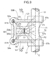
- a cam slipper 76 as a cam abutment is provided integrally or by securing by another member, in an intermediate portion between the swinging support section 57 and the valve abutments 53A and 53B, and is in contact with the valve operating cam 55 on the exhaust-side camshaft 52.
- the cam slipper 76 is disposed in an intermediate portion between the first and second support walls 58 and 59, and the support walls 58 and 59 and the cam slipper 76 are interconnected by connecting tubes 77, 77 extending in parallel to the exhaust-side rocker shaft 51. Moreover, a recess having a circular sectional shape is coaxially provided in each of the connecting tubes 77, 77 with its outer end opening into the outer surface of the exhaust-side rocker arm 50B, i.e., the outer surface of each of the first and second support walls 58 and 59.
- wall-removed portions 78, 78 are coaxially defined in the exhaust-side rocker arm 50B at locations corresponding to the cam slipper 76, and open into opposite sides of the exhaust-side rocker arm 50B, respectively.
- a through-bore 79 is provided in the exhaust-side rocker arm 50B at a location corresponding to the cam slipper 76 to coaxially connect inner ends of the wall-removed portions 78, 78 to each other, and is defined at a diameter smaller than those of the wall-removed portions 78, 78.
- the wall-removed portions 78, 78 are formed in the exhaust-side rocker arm 50B at the locations corresponding to the cam slipper 76 provided in sliding contact with the valve operating cam 55, and open into the opposite sides of the exhaust-side rocker arm 50B, i.e., the sides of the first and second support walls 58 and 59, and therefore, the weight of the entire exhaust-side rocker arm 50B can be reduced.
- the wall-removed portions 78, 78 are defined within the connecting tubes 77, 77 interconnecting the cam slipper 76 and the first and second support walls 58 and 59. Therefore, it is possible to reduce the weight of the exhaust-side rocker arm 50B, while avoiding reductions in rigidity of the first and second support walls 58 and 59 and in rigidity of supporting of the cam slipper 76.
- the weight of the exhaust-side rocker arm 50B can be reduced further by the interconnection of the wall-removed portions by the through-bore 79, and the reduction in wall thickness of the exhaust-side rocker arm 50B at the location corresponding to the cam slipper 76 can be suppressed to the minimum by defining the through-bore 79 disposed at the location corresponding to the cam slipper 76 at the diameter smaller than those of the wall-removed portions 78, 78 on the opposite sides of the through-bore 79, thereby inhibiting the reduction in rigidity of the exhaust-side rocker arm 50B at the location corresponding to the cam slipper 76.
- Fig. 11 shows a third embodiment of the present invention.
- inner ends of wall-removed portions 78, 78 may be spaced at a distance by a partition wall 80 from each other. If the wall-removed portions 78, 78 are. formed in the above manner, the wall thickness of an exhaust-side rocker arm 50C can be increased at a location corresponding to the cam slipper 76, whereby the rigidity of the exhaust-side rocker arm 50C at the location corresponding to the cam slipper 76 can be maintained.
- Fig. 12 shows a fourth embodiment of the present invention.
- reinforcing ribs 81 and 82 are provided on an exhaust-side rocker arm 50D with the cam slipper 76 sandwiched therebetween to extend a first straight line L1 passing through the center of the first tappet screw 53A, i.e., the center of the threaded bore 61A in the first boss portion 58a and the center of the cam slipper 76
- reinforcing ribs 83 and 84 are also provided on the exhaust-side rocker arm 50D with the cam slipper 76 sandwiched therebetween to extend a second straight line L2 passing through the center of the second tappet screw 53B, i.e., the center of the threaded bore 61B in the second boss portion 59a and the center of the cam slipper 76.
- the present invention is applicable to a valve operating system for an intake valve.
- a rocker arm In a valve operating system in an internal combustion engine, a rocker arm has a plurality of valve abutments provided thereon and capable of being individually put into abutment against upper ends of a plurality of engine valves cam abutments, and also has cam abutments provided thereon to come into contact with a valve operating cam. Wall-removed portions are formed in the rocker arm at locations corresponding to the cam abutments and open at opposite sides of the rocker arm. Thus, it is possible to provide a reduction in weight of the rocker arm.
Landscapes
- Engineering & Computer Science (AREA)
- Mechanical Engineering (AREA)
- General Engineering & Computer Science (AREA)
- Valve-Gear Or Valve Arrangements (AREA)
- Valve Device For Special Equipments (AREA)
Abstract
Description
- The present invention relates to a valve operating system in an internal combustion engine comprising a swinging support section provided at a base end of a rocker arm and swingably carried on an arm support portion provided in a cylinder head, a plurality of valve abutments provided at a tip end of the rocker arm and capable of being individually put into abutment against upper ends of a plurality of engine valves, and cam abutments provided on the rocker arm in an intermediate portion thereof between the swinging support section and the valve abutments to come into contact with a valve operating cam.
- Such a valve operating system is conventionally known, for example, from Japanese Patent Application Laid-open No.6-185322.
- In a valve operating system which is designed such that a plurality of engine valves are driven by a single rocker arm, the width of the rocker arm cannot help increasing, thereby bringing about increases in size and weight of the rocker arm. In the mentioned known system, however, a structure for reducing the weight of the rocker arm is not disclosed.
- Accordingly, it is an object of the present invention to reduce the weight of the rocker arm for driving the plurality of engine valves.
- To achieve the above object, according to a first aspect and feature of the present invention, there is provided a valve operating system in an internal combustion engine comprising a swinging support section provided at a base end of a rocker arm and swingably carried on an arm support portion provided in a cylinder head, a plurality of valve abutments provided at a tip end of the rocker arm and capable of being individually put into abutment against respective upper ends of a plurality of engine valves, and cam abutments provided on the rocker arm in an intermediate portion between the swinging support section and the respective valve abutments to come into contact with a valve operating cam, wherein the rocker arm has wall-removed portions formed therein at locations corresponding to the cam abutments, the wall-removed portions opening at opposite sides of the rocker arm.
- With such arrangement of the first feature, the weight of the entire rocker arm can be reduced by the wall-reduced portions provided at the locations corresponding to the cam abutments.
- According to a second aspect and feature of the present invention, in addition to the first feature, the rocker arm includes an opening in which a roller which is the cam abutment is accommodated, and a pair of coaxially disposed shaft insertion bores with its inner ends thereof opening into the opening and with its outer ends opening outwards and sideways of the rocker arm for fitting and fixing of opposite ends of a roller shaft for rotatably supporting the roller, the roller shaft being fitted and fixed in inner ends of the shaft insertion bores, with portions of the shaft insertion bores axially outer than the opposite ends of the roller shaft being left as the hollow wall-removed portions.
- With the arrangement of the second feature, the portions of the shaft insertion bores axially outer than the opposite ends of the roller shaft are left as the hollow wall-removed portions, whereby the weight of the entire rocker arm can be reduced and moreover, the length of the roller shaft can be reduced. Thus, it is possible to facilitate the assembling of the roller shaft to the rocker arm and to make the roller shaft difficult to deform, thereby ensuring the proper swinging operation of the rocker arm.
- According to a third aspect and feature of the present invention, in addition to the second feature, each of the shaft insertion bores comprises a first insertion bore portion adjacent to the opening, a second insertion bore portion connected at an inner end thereof to an outer end of the first insertion bore portion, and a step formed between the outer end of the first insertion bore portion and the inner end of the second insertion bore portion and facing on a side opposite to the opening, and the opposite ends of the roller shaft fitted respectively in the first insertion bore portions of the shaft insertion bores are disposed in caulked engagement with the step.
- With such arrangement of the third feature, the size of each of the wall-removed portions of the shaft insertion bores left as the hollow form can be increased, thereby further reducing the weight of the entire rocker arm. Moreover, the roller shaft can be fixed to the rocker arm by caulking and hence, it is possible to further facilitate the assembling of the roller shaft to the rocker arm.
- According to a fourth aspect and feature of the present invention, in addition to the second feature, the rocker arm has a pair of support walls provided thereon to extend from the swinging support section in such a manner that the valve abutments individually corresponding to the pair of engine valves are provided at tip ends of the support walls, and the opposite ends of the roller shaft formed at a length shorter than a distance between both of the support walls are fitted and fixed in the shaft insertion bores such that the wall-removed portions can be formed in the rocker arm at locations axially outer than the opposite ends of the roller shaft.
- With the fourth feature, loads from the engine valves are applied to the support walls, but the roller can be supported by the roller shaft disposed at a location kept away from portions to which the loads are applied and hence, the rigidity of supporting of the roller can be enhanced.
- According to a fifth aspect and feature of the present invention, in addition to the fourth feature, the rocker arm has a pair of cylindrical shaft support portions provided thereon over the first and second support walls and the opening to define the shaft insertion bores, respectively. With such arrangement of the fifth feature, the pair of the cylindrical shaft support portions interconnected through the roller shaft are connected to the support walls and hence, the rigidity of support walls and the rigidity of supporting of the roller can be enhanced.
- According to the sixth aspect and feature of the present invention, in addition to any of the second to fourth features, each of portions of the shaft insertion bores left as the wall-removed portions is formed into such a shape that it is enlarged gradually as approaching the side of the rocker arm.
- With such arrangement of the sixth feature, it is possible to facilitate an operation for fitting and fixing the roller shaft in the inner ends of the shaft insertion bores, leading to an enhanced assemblability.
- According to the seventh aspect and feature of the present invention, in addition to the first feature, the rocker arm has a pair of support walls provided thereon to extend from the swinging support section in such a manner that the valve abutments are provided at tip ends of the support walls; a cam slipper which is the cam abutment is provided on the rocker arm between both of the support walls; and the wall-removed portions are formed within a pair of connecting tubes which interconnect the support walls and the cam slipper.
- With the arrangement of the seventh feature, the cam slipper is continuously formed with the pair of support walls through the pair of the connecting tubes. Therefore, it is possible to reduce the weight of the rocker arm, while avoiding reductions in rigidity of the support walls and the rigidity of supporting of the cam slipper.
- The above and other objects, features and advantages of the invention will become apparent from the following description of the preferred embodiments taken in conjunction with the accompanying drawings.
- Figs.1 to 7 show a first embodiment of the present invention.
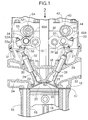
- Fig.1 is a partially vertical sectional view of an internal combustion engine;
- Fig.2 is a plan view taken in a direction of an
arrow 2 in Fig.1; - Fig.3 is a plan view of an exhaust-side rocker arm;
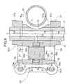
- Fig.4 is a sectional view taken along a line 4-4 in Fig.2;
- Fig.5 is a sectional view taken along a line 5-5 in Fig.2;
- Fig.6 is a sectional view taken along a line 6-6 in Fig.5;
- Fig.7 is a sectional view taken along a line 7-7 in Fig.6;
- Fig.8 is a partially vertical sectional view of an internal combustion engine, similar to Fig.1, but according to a second embodiment of the present invention;
- Fig.9 is a plan view of an exhaust-side rocker arm, similar to Fig.3, but according to the second embodiment;
- Fig.10 is a sectional view taken along a line 10-10 in Fig.9;
- Fig.11 is a sectional view similar to Fig.10, but according to a third embodiment; and
- Fig.12 is a plan view of an exhaust-side rocker arm, similar to Fig.3, but according to a fourth embodiment.
-
- A first embodiment of the present invention will be described with reference to Figs.1 to 7. Referring first to Figs.1 and 2, a multi-cylinder internal combustion engine includes a
cylinder block 15, and acylinder head 16 coupled to an upper portion of thecylinder block 15 through agasket 17. Apiston 19 is slidably received in each ofcylinders 18 provided in thecylinder block 15. Acombustion chamber 20 is defined in each of the cylinders by thecylinder block 15, thecylinder head 16 and each of thepistons 19. - Provided in the
cylinder head 16 for every cylinder are a pair ofintake valve bores 21 facing one side of a ceiling surface of thecombustion chamber 20, anintake port 22 which opens into one side (a right side in Fig. 1) of thecylinder head 16 and connected commonly to theintake valve bores 21, a pair ofexhaust valve bores 23 facing the other side of the ceiling surface of thecombustion chamber 20, and anexhaust port 24 which opens into the other side (a left side in Fig.1) of thecylinder head 16. -
Stems 25 of intake valves VI, VI capable of opening and closing theintake valve bores 21 are slidably received inguide tubes 26 mounted in thecylinder head 16, andvalve springs 28 for biasing the intake valves VI, VI upwards, i.e., in valve closing directions are mounted between thecylinder head 16 andretainers stems 25 protruding upwards from theguide tubes 26.Stems 29 of exhaust valves VE, VE as engine valves capable of opening and closing theexhaust valve bores 23 are slidably received inguide tubes 30 mounted in thecylinder head 16, andvalve springs 32 for biasing the exhaust valves VE, VE upwards, i.e., in valve closing directions are mounted between thecylinder head 16 andretainers stems 29 protruding upwards from theguide tubes 30. - The intake valves VI, VI are opened and closed by an intake-side
valve operating device 33, and the exhaust valves VE, VE are opened and closed by an exhaust-sidevalve operating device 34. Aplug insertion tube 36 is disposed to extend vertically, so that aspark plug 35 mounted in thecylinder head 16 to face a central portion of thecombustion chamber 20 is inserted into theplug insertion tube 36. Theplug insertion tube 36 is attached at its lower end to thecylinder head 16. - The intake-side
valve operating device 33 includes a pair of intake-side rocker arms side rocker shaft 39 on which the intake-side rocker arms side camshaft 40 which is rotatable about an axis parallel to therocker shaft 39. - The intake-
side rocker shaft 39 is fixedly supported byholder walls 41 provided on thecylinder head 16 between the cylinders, and intake-side rocker arms side rocker shaft 39.Tappet screws side rocker arms stems 25, so that their advanced and retracted positions can be adjusted. The intake-side camshaft 40 is operatively connected at a reduction ratio of 1/2 to a crankshaft (not shown) and rotatably carried by theholder walls 41 andcam holders 43 fastened to upper ends of theholder walls 41. - The intake-
side camshaft 40 is provided with a high-speedvalve operating cam 44 corresponding to one of the intake-side rocker arms 37, and a low-speedvalve operating cam 45 corresponding to the other intake-side rocker arm 38. Aroller 46 supported on the one intake-side rocker arm 37 is in rolling contact with the high-speedvalve operating cam 44, and a roller (not shown) supported on the other intake-side rocker arm 38 is in rolling contact with the low-speedvalve operating cam 45. - Moreover, an interlocking-motion switchover means (not shown) is provided between the intake-
side rocker arms rocker arms rocker arms rocker arms side rocker arm 37 is swung to open and close one of the intake valves VI in an operational characteristic corresponding to a cam profile of the high-speedvalve operating cam 44, while the other intake-side rocker arm 38 is swung to open and close the other intake valves VI in an operational characteristic corresponding to a cam profile of the low-speedvalve operating cam 45. During operation of the engine at the high speed, both of the intake-side rocker arms valve operating cam 44. - The exhaust-side
valve operating device 34 includes a single exhaust-side rocker arm 50A which is common to the pair of exhaust valves VE and VE, an exhaust-side rocker shaft 51 serving as an arm support portion on which the exhaust-side rocker arm 50A is swingably carried and an exhaust-side cam shaft 52 which is rotatable about an axis parallel to therocker shaft 51. - The exhaust-
side rocker shaft 51 has an axis parallel to the intake-side rocker shaft 39 and is fixedly supported by theholder wall 41, as is the intake-side rocker shaft 39. The exhaust-side rocker arm 50A is swingably carried at its base end on the exhaust-side rocker shaft 51, and first andsecond tappet screws side rocker arm 50A to abut against upper ends of the corresponding exhaust valves VE, VE, i.e., upper ends of thestems 29, so that their advanced and retracted positions can be adjusted. The exhaust-side camshaft 52 is operatively connected at a reduction ratio of 1/2 to the crankshaft (not shown) rotatably carried by theholder walls 41 andcam holders 54 fastened to the upper ends of theholder walls 41. - A
valve operating cam 55 is provided on the exhaust-side camshaft 52 in correspondence to the exhaust-side rocker arm 50A, and aroller 56 as a cam abutment axially supported on the exhaust-side rocker arm 50A is in rolling contact with thevalve operating cam 55. - Referring to Fig.3, the exhaust-
side rocker arm 50A is provided at its base end with a cylindricalswinging support section 57 through which the exhaust-side rocker shaft 51 is inserted and which is swingably carried on therocker shaft 51. The exhaust-side rocker arm 50A is further provided with first andsecond support walls connection wall 60 connecting tip ends of the first andsecond support walls - First and
second boss portions second support walls side rocker shaft 51. It is preferable that the first andsecond support walls support section 57 along a plane perpendicular to the axis of the exhaust-side rocker shaft 51, and that the first andsecond boss portions support section 57 are interconnected by the first andsecond support walls side rocker shaft 51. - The
boss portions bores roller 56 is supported on the exhaust-side rocker arm 50A in a location intermediate between the swingingsupport section 57 and the tappet screws 53A and 53B, i.e., at a location displaced from the axis of the exhaust-side rocker shaft 51. - A first straight line L1 extends through (1) the center of one 53A of the first and second tappet screws 53A and 53B which is disposed on axially one side (a lower end side in Fig. 3) of the exhaust-
side rocker shaft 51, i.e., the center of the threadedbore 61A in thefirst boss portion 58a, and (2) an area of contact (an area indicated by intersecting oblique lines in Fig.3) of thevalve operating cam 55 with theroller 56. A second straight line L2 extends through (1) the center of the other 53B of the first and second tappet screws 53A and 53B which is disposed on the axially other side (an upper end side in Fig . 3 ) of the exhaust-side rocker shaft 51, i.e., the center of the threaded bore 61B in thesecond boss portion 59a, and (2) an area of contact of thevalve operating cam 55 with theroller 56. The first and second straight lines L1 and L2 and the axis C of the exhaust-side rocker shaft 51 intersect together at intersection points P1 and P2 as viewed in the plane of the exhaust-side rocker arm 50A. The intersection points P1 and P2 are disposed at locations inside axially opposite sides of the swingingsupport section 57. In other words, the swingingsupport section 57 is formed to have such a length that their opposite ends faces are disposed outside the first and second intersection points P1 and P2. It is desirable that the first and second straight lines L1 and L2 pass through the center of the area of contact of thevalve operating cam 55 with theroller 56. - Moreover, the swinging
support section 57 is formed at a length longer than a distance between the centers of the first and second tappet screws 53A and 53B, and third and fourth straight lines L3 and L4 passing through the centers of the first and second tappet screws 53A and 53B and intersecting the axis C of the exhaust-side rocker shaft 51 at right angles are disposed inside the axially opposite ends of the swingingsupport section 57. - Referring also to Figs.4 to 6, a
rectangular opening 62 for accommodation of theroller 56 is provided in the exhaust-side rocker arm 50A between the first andsecond support walls roller shaft 63, which has a length shorter than a distance between the first andsecond support walls side rocker shaft 51, extends across theopening 62 and is fixed to theexhaust rocker arm 50A, and theroller 56 is rotatably carried on theroller shaft 63 with aneedle bearing 64 interposed therebetween. - A pair of
shaft support portions second support walls opening 62 respectively to extend in parallel to the exhaust-side rocker shaft 51. Shaft insertion bores 66, 66 are coaxially provided in theshaft support portions opening 62 and with its outer end opening outwards and sideways of the exhaust-side rocker arm 50A, i.e., outwards and sideways of the first andsecond support walls - The shaft insertion bore 66 comprises a first insertion bore
portion 66a adjacent theopening 62, a secondinsertion bore portion 66b connected at its inner end to an outer end of the first insertion boreportion 66a, and astep 66c formed between the outer end of the first insertion boreportion 66a and the inner end of the secondinsertion bore portion 66b and facing on a side opposite from theopening 62. It is desirable that the first and second insertion boreportions annular step 66c is formed between both of the insertion boreportions portions portion 66a may be circular in cross section, while the secondinsertion bore portion 66b may be non-circular in cross section. Namely, the secondinsertion bore portion 66b may be of any cross-sectional shape, if thestep 66c is formed between the first and second insertion boreportions opening 62. Moreover, it is desirable that the secondinsertion bore portion 66b is of such a shape that it is enlarged gradually as approaching a side of the exhaust-side rocker arm 50A. In the present embodiment, the secondinsertion bore portion 66b is defined as a tapered bore with its end adjacent to the exhaust-side rocker arm 50A being of a larger diameter. - The
roller shaft 63 is fitted in and fixed to inner ends of the shaft insertion bores 66, 66 with each of portions of the shaft insertion bores 66 axially outer than opposite ends of theroller shaft 63 being left in a hollow form. For such fitting and fixing, outer peripheral edges of the opposite ends of theroller shaft 63 fitted in the firstinsertion bore portions steps portions side rocker arm 50A at locations axially outside the opposite ends of theroller shaft 63 in a state in which theroller shaft 63 has been fixed to the exhaust-side rocker arm 50A. - The cylindrical
swinging support section 57 comprises a thinnercylindrical portion 57a surrounding the exhaust-side rocker shaft 51, and thickercylindrical portions cylindrical portion 57a and continuously and integrally formed at opposite ends of the thinnercylindrical portion 57a, respectively. The first andsecond support walls cylindrical portions - Referring also to Fig.7,
grooves side rocker shaft 51 are provided in an arcuate shape in lower portions of inner surfaces of the thickercylindrical portions second support walls -
Recesses roller 56 within theopening 62 are defined in portions of the upper surface of the exhaust-side rocker arm 50A, which are surrounded by the first andsecond support walls connection wall 60 and the swingingsupport section 57. - One of the
recesses 69 is defined in the exhaust-side rocker arm 50A between theshaft support portions support section 57, and theother recess 70 is defined in the exhaust-side rocker arm 50A between theshaft support portions connection wall 60. - An axially central portion of the swinging
support section 57, i.e., an axially intermediate portion of the thinnercylindrical portion 57a is disposed at a location corresponding to theplug insertion tube 36.Notches support section 57 and the exhaust-side rocker shaft 51 at the location corresponding to theplug insertion tube 36 and formed into such an arcuate shape that they are recessed on a side opposite to theplug insertion tube 36, and a portion of theplug insertion tube 36 is accommodated in thenotch 71. Moreover, thenotches support section 57 and the exhaust-side rocker shaft 51 between connections of the first andsecond support walls support section 57. - An oil injection bore 73 is provided, with its outer end opening into the
opening 62, in the swingingsupport section 57 on a side opposite to thenotch 71 with respect to the axis C of the exhaust-side rocker shaft 51. Anoil supply passage 74 is provided in the exhaust-side rocker shaft 51 to extend along the axis C of the exhaust-side rocker shaft 51, and an oil supply bore 75 is also provided in the exhaust-side rocker shaft 51 to communicate with the oil supply passage74, and is capable of communicating at its outer end with an inner end of the oil injection bore 73. Theoil supply passage 74 is connected to an oil supply source which is not shown. Therefore, it is possible to supply the oil through theoil supply passage 74 within the exhaust-side rocker shaft 51 via the oil supply bore 75 and the oil injection bore 73 to theroller 56 to lubricate theroller 56. The communication between the oil supply bore 75 and the oil injection bore 73 may be cut off depending on a swung state of the exhaust-side rocker arm 50A, but in the cut-off state, the oil supplied from the oil supply bore 75 is used for the lubrication between the swingingsupport section 57 and the exhaust-side rocker shaft 51, and the oil is also supplied to thegrooves support section 57. - The
connection wall 60 interconnecting the tip ends of the first andsecond support walls second boss portions second wall portions side rocker shaft 51, i.e., the swinging axis of the exhaust-side rocker arm 50A. Thewall portions - Moreover, the
second wall portion 60b is formed to extend in parallel to the axis of the exhaust-side rocker shaft 51 with its outer surface connected flush to outer surfaces of the first andsecond boss portions opening 62 is defined by a portion of an inner surface of thefirst wall portion 60a. - The operation of the first embodiment will be described below. In the exhaust-
side rocker arm 50A, the intersection points P1 and P2, at which (a) the first straight line L1 extending through (1) the center of one 53A of the first and second tappet screws 53A and 53B arranged in parallel to the axis C of the exhaust-side rocker shaft 51, which is disposed on the axially one side of the exhaust-side rocker shaft 51 and (2) the area of contact of thevalve operating cam 55 with theroller 56, preferably the center of such area, (b) the second straight line L2 extending through (1) the center of the other 53B of the first and second tappet screws 53A and 53B which is disposed on the axially other side (an upper end side in Fig.3) of the exhaust-side rocker shaft 51 and (2) the area of contact of thevalve operating cam 55 with theroller 56, preferably the center of such area, and (c) the axis C of the exhaust-side rocker shaft 51 intersect together as viewed in the plane of the exhaust-side rocker arm 50A, are disposed inside the axially opposite ends of the cylindrical swingingsupport section 57 swingably carried on the exhaust-side rocker shaft 51. - Therefore, even if a difference is produced between the tappet clearances in the first and second tappet screws 53A and 53B, and a large load is produced on the first or second straight line L1 , L2 to act so as to incline the exhaust-side rocker arm because the swinging
support section 57 is supported on the exhaust-side rocker shaft 51 on the first and second straight lines L1 and L2. As a result, it is also possible to prevent an uneven wear from being produced in the swingingsupport section 57 and theroller 56. - In addition, the swinging
support section 57 is formed at the length longer than the distance between the centers of the first and second tappet screws 53A and 53B, and the third and fourth straight lines L3 and L4 passing the centers of the first and second tappet screws 53A and 53B and intersecting the axis C of the exhaust-side rocker shaft 51 at the right angles are disposed inside the axially opposite ends of the swingingsupport section 57. Therefore, the exhaust-side rocker shaft 52 is supported on the exhaust-side rocker shaft 52 over the length longer than the distance between the tappet screws 53A and 53B, and the exhaust-side rocker arms 50A is supported more stably. - The
roller shaft 63 is fitted and fixed in the exhaust-side rocker arm 50A, and theroller 56 in rolling contact with thevalve operating cam 55 is rotatably carried on theroller shaft 63. However, theroller shaft 63 is shorter than the distance between the first andsecond support walls support section 57, and is fitted and fixed at the inner ends of the pair of shaft insertion bores 66, 66 which are coaxially provided in the exhaust-side rocker arm 50A with their portions axially the exhaust-side rocker arm 50A with their portions axially outer than opposite ends of theroller shaft 63 being left as the hollow wall-removedportions - Thus, the portions of the shaft insertion bores 66 which are axially outer than the opposite ends of the
roller shaft 63 are left in the hollow forms and hence, the weight of the entire exhaust-side rocker arm 50A can be reduced, and it is also possible to confirm, from the opposite sides of the exhaust-side rocker arm 50A, the state of theroller shaft 63 fixed to the rocker arm 50. Moreover, theroller shaft 63 can be formed at a relatively small length, whereby the assembling of theroller shaft 63 to the exhaust-side rocker arm 50A is facilitated. In addition, theroller shaft 63 can be formed so that it is difficult to deform, thereby ensuring a proper swinging movement of the exhaust-side rocker arm 50A. Loads from the exhaust valves VE, VE are applied to the first andsecond support walls roller 56 can be supported by theroller shaft 63 disposed at the location kept away from the load-applied portions and hence, the rigidity of supporting of theroller 56 can be enhanced. - The shaft insertion bore 66 comprises the first
insertion bore portion 66 adjacent to theopening 62 with theroller 56 accommodated therein, and the secondinsertion bore portion 66b connected at its inner end to the outer end of the firstinsertion bore portion 66 to form thestep 66c facing on the side opposite from theopening 62 between the first and second insertion bore 63 fitted in the firstinsertion bore portions steps 66c, respectively, whereby theroller shaft 63 is fitted and fixed in the shaft insertion bores 66, 66. Therefore, the portions of the shaft insertion bores 66, 66 left in the hollow forms, i.e., the wall-removedportions portions side rocker arm 50A can be further reduced. Further, since theroller shaft 63 is fixed in the caulked manner to the exhaust-side rocker arm 50A, the assembling of theroller shaft 63 to the exhaust-side rocker arm 50A is further facilitated. - Additionally, the portion of the shaft insertion bore 66 left as the wall-removed
portion 67, i.e., the secondinsertion bore portion 66b, is of such shape that it is enlarged gradually as approaching the portion adjacent to the side of the exhaust-side rocker arm 50A. Therefore, an operation is facilitated for fitting and fixing theroller shaft 63 in the inner end of the shaft insertion bore 66, whereby the assemblability of the roller shaft can be enhanced. - Further, the pair of cylindrical
shaft support portions side rocker arm 50A over the first andsecond support walls opening 62, and the pair of cylindricalshaft support portions roller shaft 63 are connected to thesupport walls support walls roller 56 can be further enhanced. - The cylindrical
swinging support section 57 provided at the base end of the exhaust-side rocker arm 50A so that it is swingably supported by the exhaust-side rocker shaft 51, comprises the thinnercylindrical portion 57a surrounding the exhaust-side rocker shaft 51, and the thickercylindrical portions cylindrical portion 57a surrounding the exhaust-side rocker shaft 51 and integrally connected to the axially opposite ends of the thinnercylindrical portion 57a, respectively. Therefore, the central portion of the swingingsupport section 57 can be formed at a smaller thickness to avoid an increase in weight of the exhaust-side rocker arm 50A, while the opposite ends of the swingingsupport section 57 having a possibility that a large load may be applied, can be formed at a larger thickness to enhance the rigidity of supporting of the exhaust-side rocker arm 50A and the durability of the latter. - In addition, the
grooves side rocker shaft 51 are provided in the inner surfaces of the opposite ends of the swingingsupport section 57 along the axis of the exhaust-side rocker shaft 51, i.e., in the inner surfaces of the thickercylindrical portions support section 57 and the exhaust-side rocker shaft 51, and even if the exhaust-side rocker arm 50A is inclined, an uneven wear can be prevented to the utmost from being produced, leading to an enhanced durability. Moreover, thegrooves support section 57 at its opposite ends and hence, the weight of the exhaust-side rocker arm 50A cannot be increased, and a reduction in rigidity of the swingingsupport section 57 can be inhibited. - Furthermore, the first and
second support walls support section 57 at the locations corresponding to thegrooves support section 57 due to the provision of thegrooves second support walls - The outer periphery of the exhaust-
side rocker arm 50A is formed by the swingingsupport section 57, thefirst support wall 58, thesecond support wall 59 and theconnection wall 60, and therecesses side rocker arm 50A by the portions surrounded by the swingingsupport section 57, thefirst support wall 58, thesecond support wall 59 and theconnection wall 60. Therefore, it is possible to provide a reduction in weight of the exhaust-side rocker arm 50A, while avoiding a reduction in rigidity of the exhaust-side rocker arm 50A. - Moreover, one of the
recesses 69 is disposed between the pair ofshaft support portions support section 57, and the oil can be supplied to theroller 56 accommodated in theopening 62. Therefore, the oil scattered within the valve operating chamber can be reliably accumulated at a portion of the exhaust-side rocker arm 50A which is swung in a relatively small amount, thereby lubricating theroller 56, and hence, it is unnecessary to provide a passage for supplying the oil to theroller 56 in the exhaust-side rocker arm 50A, thereby reducing the number of steps of processing the exhaust-side rocker arm 50A. - The
other recess 70 is defined in the exhaust-side rocker arm 50A between theshaft support portions connection wall 60 to enable the supplying of the oil to theroller 56 and hence, the weight of the tip end of the exhaust-side rocker arm 50A can be reduced to alleviate the inertial weight, while performing the lubrication of theroller 56. - The axially central portion of the swinging
support section 57 in the exhaust-side rocker arm 50A is disposed at the location corresponding to theplug insertion tube 36 mounted in thecylinder head 16, and thenotches plug insertion tube 36 are provided in the swingingsupport section 57 and the exhaust-side rocker shaft 51 at the location corresponding to theplug insertion tube 36. Therefore, it is possible not only to reduce the weight of the exhaust-side rocker arm 50A, but also the exhaust-side rocker shaft 51 and theplug insertion tube 36 can be disposed in the proximity to each other in such a manner that a portion of theplug insertion tube 36 is accommodated in thenotch 71, and the limitation of the layout of the exhaust-side rocker arm 50A within the valve operating chamber can be moderated to contribute to the compactness of the entire engine. - Moreover, the
notches support section 57 and the exhaust-side rocker shaft 51 between the connections of the first andsecond support walls support section 57 and hence, thenotches notch 71 in the exhaust-side rocker arm 50A to reduce the weight of the exhaust-side rocker arm 50A. - The oil is supplied from the
oil supply passage 74 in the exhaust-side rocker shaft 51 through the oil supply bore 75 and the oil injection bore 73 to theroller 56, and the oil injection bore 73 is provided in the swingingsupport section 57 on the side opposite to thenotch 71, with respect to the axis C of the exhaust-side rocker shaft 51, which notch is provided in the swingingsupport section 57 in such a manner that an outer surface of a portion of the exhaust-side rocker shaft 71 provided with thenotch 72 faces thenotch 71. Therefore, it is possible to conduct a boring for the oil injection bore 73 from the side of thenotch 71, thereby facilitating the boring for the oil injection bore 73. - The first and
second boss portions side rocker arm 50A and arranged in the direction along the axis C of the exhaust-side rocker shaft 51, but they are interconnected by theconnection wall 60. Therefore, the rigidity of the tip end of the exhaust-side rocker arm 50A driving the pair of exhaust valves VE, VE can be enhanced sufficiently and moreover, theconnection wall 60 comprises the first andsecond wall portions side rocker shaft 51, i.e., the swinging axis of the exhaust-side rocker arm 50A. Therefore, it is possible to suppress the increase in weight of the exhaust-side rocker arm 50A due to theconnection wall 60 to the minimum, while maintaining the sufficient connection rigidity. In addition, thesecond wall portion 60b of theconnection wall 60 is formed to extend in parallel to the axis of the exhaust-side rocker shaft 51, so that its outer surface is connected flush to the outer surfaces of the tip ends of the first andsecond boss portions connection wall 60 and theboss portions side rocker arm 50A, while sufficiently enhancing the rigidity of the tip end of the exhaust-side rocker arm 50A. - Further, one side of the
opening 62 provided in the exhaust-side rocker arm 50A to accommodate theroller 56 is formed by the inner surface of thefirst wall portion 60a of theconnection wall 60, and theconnection wall 60 can be disposed in proximity to theroller 56, thereby enhancing the rigidity of supporting of theroller 56. - Figs.8 to 10 show a second embodiment of the present invention, wherein portions or components corresponding to those in the first embodiment are designated by like reference characters.
- In the exhaust-
side rocker arm 50B of the exhaust-sidevalve operating device 34, acam slipper 76 as a cam abutment is provided integrally or by securing by another member, in an intermediate portion between the swingingsupport section 57 and thevalve abutments valve operating cam 55 on the exhaust-side camshaft 52. - The
cam slipper 76 is disposed in an intermediate portion between the first andsecond support walls support walls cam slipper 76 are interconnected by connectingtubes side rocker shaft 51. Moreover, a recess having a circular sectional shape is coaxially provided in each of the connectingtubes side rocker arm 50B, i.e., the outer surface of each of the first andsecond support walls portions side rocker arm 50B at locations corresponding to thecam slipper 76, and open into opposite sides of the exhaust-side rocker arm 50B, respectively. A through-bore 79 is provided in the exhaust-side rocker arm 50B at a location corresponding to thecam slipper 76 to coaxially connect inner ends of the wall-removedportions portions - In the second embodiment, the wall-removed
portions side rocker arm 50B at the locations corresponding to thecam slipper 76 provided in sliding contact with thevalve operating cam 55, and open into the opposite sides of the exhaust-side rocker arm 50B, i.e., the sides of the first andsecond support walls side rocker arm 50B can be reduced. - Moreover, the wall-removed
portions tubes cam slipper 76 and the first andsecond support walls side rocker arm 50B, while avoiding reductions in rigidity of the first andsecond support walls cam slipper 76. - The weight of the exhaust-
side rocker arm 50B can be reduced further by the interconnection of the wall-removed portions by the through-bore 79, and the reduction in wall thickness of the exhaust-side rocker arm 50B at the location corresponding to thecam slipper 76 can be suppressed to the minimum by defining the through-bore 79 disposed at the location corresponding to thecam slipper 76 at the diameter smaller than those of the wall-removedportions bore 79, thereby inhibiting the reduction in rigidity of the exhaust-side rocker arm 50B at the location corresponding to thecam slipper 76. - Fig. 11 shows a third embodiment of the present invention. In the third embodiment, inner ends of wall-removed
portions partition wall 80 from each other. If the wall-removedportions side rocker arm 50C can be increased at a location corresponding to thecam slipper 76, whereby the rigidity of the exhaust-side rocker arm 50C at the location corresponding to thecam slipper 76 can be maintained. - Fig. 12 shows a fourth embodiment of the present invention. In the fourth embodiment, reinforcing
ribs 81 and 82 are provided on an exhaust-side rocker arm 50D with thecam slipper 76 sandwiched therebetween to extend a first straight line L1 passing through the center of thefirst tappet screw 53A, i.e., the center of the threadedbore 61A in thefirst boss portion 58a and the center of thecam slipper 76, and reinforcingribs side rocker arm 50D with thecam slipper 76 sandwiched therebetween to extend a second straight line L2 passing through the center of thesecond tappet screw 53B, i.e., the center of the threaded bore 61B in thesecond boss portion 59a and the center of thecam slipper 76. - According to the fourth embodiment, it is possible to further enhance the rigidity of the exhaust-
side rocker arm 50D, and it is also possible to further effectively prevent an uneven wear from being produced in the swingingsupport section 57 and thecam slipper 76. - Although the embodiments of the present invention have been described in detail, it will be understood that the present invention is not limited to the above-described embodiments, and various modifications in design may be made without departing from the spirit and scope of the invention defined in claims.
- For example, the present invention is applicable to a valve operating system for an intake valve.
- In a valve operating system in an internal combustion engine, a rocker arm has a plurality of valve abutments provided thereon and capable of being individually put into abutment against upper ends of a plurality of engine valves cam abutments, and also has cam abutments provided thereon to come into contact with a valve operating cam. Wall-removed portions are formed in the rocker arm at locations corresponding to the cam abutments and open at opposite sides of the rocker arm. Thus, it is possible to provide a reduction in weight of the rocker arm.
Claims (7)
- A valve operating system in an internal combustion engine comprising a swinging support section (57) provided at a base end of a rocker arm (50A, 50B, 50C, 50D) and swingably carried on an arm support portion (51) provided in a cylinder head (16), a plurality of valve abutments (53A and 53B) provided at a tip end of said rocker arm (50A, 50B, 50C) and capable of being individually put into abutment against respective upper ends of a plurality of engine valves (VE), and cam abutments (56, 76) provided on said rocker arm (50A, 50B, 50C, 50D) in an intermediate portion between said swinging support section (57) and said respective valve abutments (53A and 53B) to come into contact with a valve operating cam (55), wherein said rocker arm (50A, 50B, 50C, 50D) has wall-removed portions (67 and 78) formed therein at locations corresponding to said cam abutments (56 and 76), said wall-removed portions (67 and 78) opening at opposite sides of said rocker arm (50A, 50B, 50C).
- A valve operating system in an internal combustion engine according to claim 1, wherein said rocker arm (50A) includes an opening (62) in which a roller (56) which is said cam abutment is accommodated, and a pair of coaxially disposed shaft insertion bores (66) with its inner ends thereof opening into said opening (62) and with its outer ends thereof opening outwards and sideways of said rocker arm (50A) for fitting and fixing of opposite ends of a roller shaft (63) for rotatably supporting said roller (56), said roller shaft (63) being fitted and fixed in inner ends of said shaft insertion bores (66), with portions of said shaft insertion bores (66) axially outer than the opposite ends of said roller shaft (63) being left as the hollow wall-removed portions (67).
- A valve operating system in an internal combustion engine according to claim 2, wherein each of said shaft insertion bores (66) comprises a first insertion bore portion (66a) adjacent to said opening (62), a second insertion bore portion (66b) connected at an inner end thereof to an outer end of said first insertion bore portion (66a), and a step (66c) formed between the outer end of said first insertion bore portion (66a) and the inner end of said second insertion bore portion (66b) and facing on a side opposite to said opening (62), and the opposite ends of said roller shaft (63) fitted respectively in said first insertion bore portions (66a) of said shaft insertion bores (66) are disposed in caulked engagement with said step (66c).
- A valve operating system in an internal combustion engine according to claim 2, wherein said rocker arm (50A) has a pair of support walls (58 and 59) provided thereon to extend from said swinging support section (57) in such a manner that said valve abutments (53A and 53B) individually corresponding to the pair of engine valves (VE) are provided at tip ends of the support walls, and the opposite ends of said roller shaft (63) formed at a length shorter than a distance between both of said support walls (58 and 59) are fitted and fixed in said shaft insertion bores (66) such that said wall-removed portions (67) can be formed in said rocker arm (50A) at locations axially outer than the opposite ends of said roller shaft (63).
- A valve operating system in an internal combustion engine according to claim 4, wherein said rocker arm (50A) has a pair of cylindrical shaft support portions (65) provided thereon over said first and second support walls (58 and 59) and said opening (62) to define said shaft insertion bores (66), respectively.
- A valve operating system in an internal combustion engine according to any of claims 2 to 5, wherein each of portions of said shaft insertion bores (66) left as the wall-removed portions (67) is formed into such a shape that it is enlarged gradually as approaching the side of said rocker arm (50A).
- A valve operating system in an internal combustion engine according to claim 1, wherein said rocker arm (50B, 50C, 50D) has a pair of support walls (58 and 59 ) provided thereon to extend from said swinging support section (57) in such a manner that said valve abutments (53A and 53B) are provided at tip ends of said support walls; a cam slipper (76) which is said cam abutment is provided on said rocker arm (50B, 50C, 50D) between both of said support walls (58 and 59); and said wall-removed portions (78) are formed within a pair of connecting tubes (77) which interconnect said support walls (58 and 59) and said cam slipper (76).
Applications Claiming Priority (2)
| Application Number | Priority Date | Filing Date | Title |
|---|---|---|---|
| JP37083599A JP3523134B2 (en) | 1999-12-27 | 1999-12-27 | Valve train for internal combustion engine |
| JP37083599 | 1999-12-27 |
Publications (3)
| Publication Number | Publication Date |
|---|---|
| EP1152126A2 true EP1152126A2 (en) | 2001-11-07 |
| EP1152126A3 EP1152126A3 (en) | 2002-07-24 |
| EP1152126B1 EP1152126B1 (en) | 2004-10-27 |
Family
ID=18497684
Family Applications (1)
| Application Number | Title | Priority Date | Filing Date |
|---|---|---|---|
| EP00128353A Expired - Lifetime EP1152126B1 (en) | 1999-12-27 | 2000-12-22 | Valve operating system in internal combustion engine |
Country Status (8)
| Country | Link |
|---|---|
| US (1) | US6418898B2 (en) |
| EP (1) | EP1152126B1 (en) |
| JP (1) | JP3523134B2 (en) |
| CN (1) | CN1118616C (en) |
| BR (1) | BR0006286B1 (en) |
| CA (1) | CA2329586C (en) |
| DE (1) | DE60015298T2 (en) |
| TW (1) | TW475960B (en) |
Cited By (1)
| Publication number | Priority date | Publication date | Assignee | Title |
|---|---|---|---|---|
| FR2881972A1 (en) * | 2005-02-16 | 2006-08-18 | Metaltemple Soc Par Actions Si | One-piece casting with recessed cam for vehicle gearbox control component has body with bore and peripheral fixing for over-moulded insert |
Families Citing this family (5)
| Publication number | Priority date | Publication date | Assignee | Title |
|---|---|---|---|---|
| JP4456808B2 (en) * | 2002-06-07 | 2010-04-28 | 日立オートモティブシステムズ株式会社 | Valve operating device for internal combustion engine |
| TWI237087B (en) | 2002-12-17 | 2005-08-01 | Mitsubishi Motors Corp | Valve system for internal combustion engine |
| US7305946B2 (en) | 2004-11-30 | 2007-12-11 | Hitachi, Ltd. | Variable valve operating apparatus for internal combustion engine |
| DE102007021855A1 (en) * | 2007-05-10 | 2008-11-13 | Schaeffler Kg | Rocker arm of an internal combustion engine |
| DE102013205533A1 (en) | 2013-03-28 | 2014-10-02 | Schaeffler Technologies Gmbh & Co. Kg | Method for mounting a valve train of an internal combustion engine |
Citations (1)
| Publication number | Priority date | Publication date | Assignee | Title |
|---|---|---|---|---|
| JPH06185322A (en) | 1992-12-22 | 1994-07-05 | Aisin Seiki Co Ltd | Engine valve gear |
Family Cites Families (9)
| Publication number | Priority date | Publication date | Assignee | Title |
|---|---|---|---|---|
| GB2179700B (en) * | 1985-08-29 | 1989-08-09 | Nissan Motor | Rocker arm arrangement for multi-valve internal combustion engine |
| US4628874A (en) * | 1985-10-30 | 1986-12-16 | Eaton Corporation | Roller follower axle retention |
| DE4229411A1 (en) * | 1992-09-03 | 1994-03-10 | Bayerische Motoren Werke Ag | Rocker arms for pair of engine lift valves - form triangular shape with connecting bar, and has guide fixed to connecting bar |
| US5259346A (en) * | 1992-11-05 | 1993-11-09 | Henley Manufacturing Holding Company, Inc. | Rocker arm of the cam-follower type for operating two valves |
| DE4494320C1 (en) * | 1993-06-18 | 1998-01-08 | Schaeffler Waelzlager Kg | Gas-inlet or -outlet valve lever |
| DE19537641A1 (en) * | 1995-10-10 | 1997-04-17 | Bayerische Motoren Werke Ag | Point bearing tappet for IC-engine valve |
| DE19621463A1 (en) * | 1996-05-29 | 1997-12-04 | Schaeffler Waelzlager Kg | Cam follower of a valve train of an internal combustion engine designed as a rocker arm or rocker arm |
| US5908015A (en) * | 1996-07-06 | 1999-06-01 | Meta Motoren- Und Energie Technik Gmbh | Arrangement for interrupting the flow of force between a camshaft and a valve |
| US6237552B1 (en) * | 1999-08-31 | 2001-05-29 | Allen James Hoag, Jr. | Motorcycle rocker arm |
-
1999
- 1999-12-27 JP JP37083599A patent/JP3523134B2/en not_active Expired - Lifetime
-
2000
- 2000-12-15 TW TW089126920A patent/TW475960B/en active
- 2000-12-22 CA CA002329586A patent/CA2329586C/en not_active Expired - Fee Related
- 2000-12-22 EP EP00128353A patent/EP1152126B1/en not_active Expired - Lifetime
- 2000-12-22 DE DE60015298T patent/DE60015298T2/en not_active Expired - Lifetime
- 2000-12-26 US US09/745,992 patent/US6418898B2/en not_active Expired - Fee Related
- 2000-12-27 CN CN00136489A patent/CN1118616C/en not_active Expired - Fee Related
- 2000-12-27 BR BRPI0006286-3A patent/BR0006286B1/en not_active IP Right Cessation
Patent Citations (1)
| Publication number | Priority date | Publication date | Assignee | Title |
|---|---|---|---|---|
| JPH06185322A (en) | 1992-12-22 | 1994-07-05 | Aisin Seiki Co Ltd | Engine valve gear |
Cited By (1)
| Publication number | Priority date | Publication date | Assignee | Title |
|---|---|---|---|---|
| FR2881972A1 (en) * | 2005-02-16 | 2006-08-18 | Metaltemple Soc Par Actions Si | One-piece casting with recessed cam for vehicle gearbox control component has body with bore and peripheral fixing for over-moulded insert |
Also Published As
| Publication number | Publication date |
|---|---|
| JP2001182508A (en) | 2001-07-06 |
| CN1301913A (en) | 2001-07-04 |
| CA2329586C (en) | 2006-08-29 |
| CN1118616C (en) | 2003-08-20 |
| EP1152126B1 (en) | 2004-10-27 |
| DE60015298T2 (en) | 2005-03-24 |
| BR0006286B1 (en) | 2008-11-18 |
| BR0006286A (en) | 2001-09-25 |
| EP1152126A3 (en) | 2002-07-24 |
| US6418898B2 (en) | 2002-07-16 |
| TW475960B (en) | 2002-02-11 |
| JP3523134B2 (en) | 2004-04-26 |
| US20010015188A1 (en) | 2001-08-23 |
| DE60015298D1 (en) | 2004-12-02 |
| CA2329586A1 (en) | 2001-06-27 |
Similar Documents
| Publication | Publication Date | Title |
|---|---|---|
| CN110725726B (en) | Valve train pivot bracket assembly with multi-functional cover | |
| CA2363415C (en) | Lubricating structure in internal combustion engine | |
| CA2329586C (en) | Valve operating system in internal combustion engine | |
| EP1113150B1 (en) | Valve operating system for an internal combustion engine | |
| US6920856B2 (en) | Camshaft mounting structure for a cylinder head | |
| EP1113149B1 (en) | Valve operating system in internal combustion engine | |
| EP1113148B1 (en) | Valve operating system in internal combustion engine | |
| US6708658B2 (en) | Internal combustion engine | |
| JP3592600B2 (en) | Valve train for internal combustion engine | |
| JP3358960B2 (en) | SOHC type internal combustion engine | |
| JP3715194B2 (en) | Valve operating device for internal combustion engine | |
| JP2001182513A (en) | Valve train for internal combustion engine | |
| JP3535430B2 (en) | Valve train for internal combustion engine | |
| JP3523132B2 (en) | Valve train for internal combustion engine | |
| JP2002129914A (en) | Valve train for internal combustion engine | |
| JP2001182514A (en) | Valve train for internal combustion engine | |
| JPS6296712A (en) | Lubricating oil passage structure of OHC/V-type multi-cylinder engine |
Legal Events
| Date | Code | Title | Description |
|---|---|---|---|
| PUAI | Public reference made under article 153(3) epc to a published international application that has entered the european phase |
Free format text: ORIGINAL CODE: 0009012 |
|
| AK | Designated contracting states |
Kind code of ref document: A2 Designated state(s): AT BE CH CY DE DK ES FI FR GB GR IE IT LI LU MC NL PT SE TR |
|
| AX | Request for extension of the european patent |
Free format text: AL;LT;LV;MK;RO;SI |
|
| PUAL | Search report despatched |
Free format text: ORIGINAL CODE: 0009013 |
|
| AK | Designated contracting states |
Kind code of ref document: A3 Designated state(s): AT BE CH CY DE DK ES FI FR GB GR IE IT LI LU MC NL PT SE TR |
|
| AX | Request for extension of the european patent |
Free format text: AL;LT;LV;MK;RO;SI |
|
| 17P | Request for examination filed |
Effective date: 20030123 |
|
| 17Q | First examination report despatched |
Effective date: 20030303 |
|
| AKX | Designation fees paid |
Designated state(s): DE FR GB |
|
| GRAP | Despatch of communication of intention to grant a patent |
Free format text: ORIGINAL CODE: EPIDOSNIGR1 |
|
| GRAJ | Information related to disapproval of communication of intention to grant by the applicant or resumption of examination proceedings by the epo deleted |
Free format text: ORIGINAL CODE: EPIDOSDIGR1 |
|
| GRAP | Despatch of communication of intention to grant a patent |
Free format text: ORIGINAL CODE: EPIDOSNIGR1 |
|
| GRAS | Grant fee paid |
Free format text: ORIGINAL CODE: EPIDOSNIGR3 |
|
| GRAA | (expected) grant |
Free format text: ORIGINAL CODE: 0009210 |
|
| AK | Designated contracting states |
Kind code of ref document: B1 Designated state(s): DE FR GB |
|
| REG | Reference to a national code |
Ref country code: GB Ref legal event code: FG4D |
|
| REG | Reference to a national code |
Ref country code: IE Ref legal event code: FG4D |
|
| REF | Corresponds to: |
Ref document number: 60015298 Country of ref document: DE Date of ref document: 20041202 Kind code of ref document: P |
|
| ET | Fr: translation filed | ||
| PLBE | No opposition filed within time limit |
Free format text: ORIGINAL CODE: 0009261 |
|
| STAA | Information on the status of an ep patent application or granted ep patent |
Free format text: STATUS: NO OPPOSITION FILED WITHIN TIME LIMIT |
|
| 26N | No opposition filed |
Effective date: 20050728 |
|
| PGFP | Annual fee paid to national office [announced via postgrant information from national office to epo] |
Ref country code: FR Payment date: 20101224 Year of fee payment: 11 |
|
| PGFP | Annual fee paid to national office [announced via postgrant information from national office to epo] |
Ref country code: GB Payment date: 20101222 Year of fee payment: 11 |
|
| PGFP | Annual fee paid to national office [announced via postgrant information from national office to epo] |
Ref country code: DE Payment date: 20101215 Year of fee payment: 11 |
|
| GBPC | Gb: european patent ceased through non-payment of renewal fee |
Effective date: 20111222 |
|
| REG | Reference to a national code |
Ref country code: FR Ref legal event code: ST Effective date: 20120831 |
|
| PG25 | Lapsed in a contracting state [announced via postgrant information from national office to epo] |
Ref country code: GB Free format text: LAPSE BECAUSE OF NON-PAYMENT OF DUE FEES Effective date: 20111222 |
|
| PG25 | Lapsed in a contracting state [announced via postgrant information from national office to epo] |
Ref country code: FR Free format text: LAPSE BECAUSE OF NON-PAYMENT OF DUE FEES Effective date: 20120102 |
|
| REG | Reference to a national code |
Ref country code: DE Ref legal event code: R119 Ref document number: 60015298 Country of ref document: DE Effective date: 20130702 |
|
| PG25 | Lapsed in a contracting state [announced via postgrant information from national office to epo] |
Ref country code: DE Free format text: LAPSE BECAUSE OF NON-PAYMENT OF DUE FEES Effective date: 20130702 |