EP1152110A2 - Locking power clamp - Google Patents
Locking power clamp Download PDFInfo
- Publication number
- EP1152110A2 EP1152110A2 EP00308762A EP00308762A EP1152110A2 EP 1152110 A2 EP1152110 A2 EP 1152110A2 EP 00308762 A EP00308762 A EP 00308762A EP 00308762 A EP00308762 A EP 00308762A EP 1152110 A2 EP1152110 A2 EP 1152110A2
- Authority
- EP
- European Patent Office
- Prior art keywords
- clamp
- clamp assembly
- movement
- link arm
- assembly
- Prior art date
- Legal status (The legal status is an assumption and is not a legal conclusion. Google has not performed a legal analysis and makes no representation as to the accuracy of the status listed.)
- Withdrawn
Links
- 230000002093 peripheral effect Effects 0.000 claims abstract description 6
- 239000012530 fluid Substances 0.000 claims abstract description 3
- 230000003252 repetitive effect Effects 0.000 claims abstract description 3
- 230000000712 assembly Effects 0.000 claims 3
- 238000000429 assembly Methods 0.000 claims 3
- 230000007246 mechanism Effects 0.000 description 33
- 230000008901 benefit Effects 0.000 description 4
- 238000010276 construction Methods 0.000 description 2
- 239000000356 contaminant Substances 0.000 description 1
- -1 dirt Substances 0.000 description 1
- 230000002349 favourable effect Effects 0.000 description 1
- 230000002452 interceptive effect Effects 0.000 description 1
- 230000004048 modification Effects 0.000 description 1
- 238000012986 modification Methods 0.000 description 1
- 239000011435 rock Substances 0.000 description 1
- 239000004576 sand Substances 0.000 description 1
- 238000007789 sealing Methods 0.000 description 1
Images


Classifications
-
- B—PERFORMING OPERATIONS; TRANSPORTING
- B65—CONVEYING; PACKING; STORING; HANDLING THIN OR FILAMENTARY MATERIAL
- B65D—CONTAINERS FOR STORAGE OR TRANSPORT OF ARTICLES OR MATERIALS, e.g. BAGS, BARRELS, BOTTLES, BOXES, CANS, CARTONS, CRATES, DRUMS, JARS, TANKS, HOPPERS, FORWARDING CONTAINERS; ACCESSORIES, CLOSURES, OR FITTINGS THEREFOR; PACKAGING ELEMENTS; PACKAGES
- B65D90/00—Component parts, details or accessories for large containers
- B65D90/008—Doors for containers, e.g. ISO-containers
-
- B—PERFORMING OPERATIONS; TRANSPORTING
- B65—CONVEYING; PACKING; STORING; HANDLING THIN OR FILAMENTARY MATERIAL
- B65D—CONTAINERS FOR STORAGE OR TRANSPORT OF ARTICLES OR MATERIALS, e.g. BAGS, BARRELS, BOTTLES, BOXES, CANS, CARTONS, CRATES, DRUMS, JARS, TANKS, HOPPERS, FORWARDING CONTAINERS; ACCESSORIES, CLOSURES, OR FITTINGS THEREFOR; PACKAGING ELEMENTS; PACKAGES
- B65D90/00—Component parts, details or accessories for large containers
-
- E—FIXED CONSTRUCTIONS
- E05—LOCKS; KEYS; WINDOW OR DOOR FITTINGS; SAFES
- E05B—LOCKS; ACCESSORIES THEREFOR; HANDCUFFS
- E05B51/00—Operating or controlling locks or other fastening devices by other non-mechanical means
- E05B51/02—Operating or controlling locks or other fastening devices by other non-mechanical means by pneumatic or hydraulic means
-
- E—FIXED CONSTRUCTIONS
- E05—LOCKS; KEYS; WINDOW OR DOOR FITTINGS; SAFES
- E05C—BOLTS OR FASTENING DEVICES FOR WINGS, SPECIALLY FOR DOORS OR WINDOWS
- E05C5/00—Fastening devices with bolts moving otherwise than only rectilinearly and only pivotally or rotatively
-
- E—FIXED CONSTRUCTIONS
- E05—LOCKS; KEYS; WINDOW OR DOOR FITTINGS; SAFES
- E05B—LOCKS; ACCESSORIES THEREFOR; HANDCUFFS
- E05B15/00—Other details of locks; Parts for engagement by bolts of fastening devices
- E05B15/0086—Toggle levers
-
- E—FIXED CONSTRUCTIONS
- E05—LOCKS; KEYS; WINDOW OR DOOR FITTINGS; SAFES
- E05B—LOCKS; ACCESSORIES THEREFOR; HANDCUFFS
- E05B17/00—Accessories in connection with locks
- E05B17/0025—Devices for forcing the wing firmly against its seat or to initiate the opening of the wing
- E05B17/0029—Devices for forcing the wing firmly against its seat or to initiate the opening of the wing motor-operated
-
- Y—GENERAL TAGGING OF NEW TECHNOLOGICAL DEVELOPMENTS; GENERAL TAGGING OF CROSS-SECTIONAL TECHNOLOGIES SPANNING OVER SEVERAL SECTIONS OF THE IPC; TECHNICAL SUBJECTS COVERED BY FORMER USPC CROSS-REFERENCE ART COLLECTIONS [XRACs] AND DIGESTS
- Y10—TECHNICAL SUBJECTS COVERED BY FORMER USPC
- Y10T—TECHNICAL SUBJECTS COVERED BY FORMER US CLASSIFICATION
- Y10T292/00—Closure fasteners
- Y10T292/08—Bolts
- Y10T292/0911—Hooked end
- Y10T292/0913—Sliding and swinging
- Y10T292/0914—Operating means
- Y10T292/0917—Lever
-
- Y—GENERAL TAGGING OF NEW TECHNOLOGICAL DEVELOPMENTS; GENERAL TAGGING OF CROSS-SECTIONAL TECHNOLOGIES SPANNING OVER SEVERAL SECTIONS OF THE IPC; TECHNICAL SUBJECTS COVERED BY FORMER USPC CROSS-REFERENCE ART COLLECTIONS [XRACs] AND DIGESTS
- Y10—TECHNICAL SUBJECTS COVERED BY FORMER USPC
- Y10T—TECHNICAL SUBJECTS COVERED BY FORMER US CLASSIFICATION
- Y10T292/00—Closure fasteners
- Y10T292/08—Bolts
- Y10T292/1043—Swinging
- Y10T292/1075—Operating means
- Y10T292/1082—Motor
Definitions
- This invention broadly relates to a novel locking power clamp uniquely designed for use in holding a door of a container in a closed position. More specifically, the invention relates to a special new locking power clamp suitable for use with industrial vacuum loader trucks, wherein a clamping system is required to hold the rear door of the vacuum loader in a tightly closed and sealed position.
- the present invention consists of a new locking power clamp assembly for repetitive use in uniformly and securely clamping a closure member over a container opening, said clamp assembly comprising: a clamp arm member having a clamping contact surface thereon, said clamp arm member being of elongated dimension and being capable of generally rotational movement, such that when the clamp assembly is opened, the clamp arm member will move in a generally perpendicular direction away from the plane of the closure member and also will move in a radial direction away from a peripheral edge of the closure member, at least one frame member, at least two link arm members, each being of different length, a fluid operated piston and cylinder assembly, with the piston being connected to one of the link arm members, and the cylinder being connected to said frame member, a rotator member secured to the frame member to support and assist proper movement of the clamp arm member.
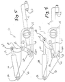
- the locking power clamp is designated 10 in Figures 1, 2 and 3.
- the clamp mechanism as shown in Figures 1, 2 and 3 uses a sliding pivot pin designated 12 which moves within a slot designated 14 when the clamp mechanism is actuated or deactuated for purposes of moving the clamp arm 16 to an open position as shown in Figure 3 relative, to the closed position of the clamp arm 16 as indicated in Figures in 1 and 2.
- FIG. 1 First with respect to Figure 2, this Figure shows the clamp mechanism 10 in closed or fully clamped position. In this position the cylinder 20 and piston rod 22 are in fully extended position which thereby pushes or moves the link arm 24 into a fully forward position. This full forward position is the opposite of the fully withdrawn position of link arm 24 as shown in Figure 3, when the cylinder 20 and piston rod 22 are in full retracted position.
- pivot arm 25 In the retracted position of the linked arm 24, as shown in Figure 3, pivot arm 25 is also in retracted position and this has caused the lower portion 24a of link arm 24 to be moved in a forward position (or to the right) as shown in the drawing Figure 3, thus causing the pivot pin or slide pin 12 to move forward or to the right in the slot 14.
- This moves the rear 16a of the clamping arm 16 into a lower position, which then pivots the clamp arm 16 into an upward and withdrawn position, due to its rotation about the rotator member 28; and also simultaneously moves the clamp arm 16 into an outer position which is withdrawn from the actual closed clamped position shown by the dotted at line 29 in Figure 3.
- the fully open position of the clamp member surface is designated by the dotted line at 31.
- the distance from fully clamped position 29 to open position 31 is broadly stated about one-half inch to six inches or more, and preferably this extent of movement would be three-quarters of an inch to one and a half inches. With most preferred results being obtained when the amount of movement from closed position 29 to open position 31 is approximately one inch.
- movement of the clamp surface 16b in an up and down (i.e., radial) direction is designated by the distance between the dotted line at 33 and the dotted line at 35.
- This distance between position 33 and position 35 can be from approximately one-half inch to about five inches or more, with preferred results being obtained when the distance between position 33 and position 35 is kept to a dimension between about three-quarters inch and one and one-quarter inch. With best results being obtained when the distance between position 33 and position 35 is kept at about one inch.
- the clamping mechanism of Figures 1, 2 and 3 is also designed and constructed to use the bracket member 40, which acts as a support for the internal working of the clamping mechanism and for housing of the cylinder 20 and piston rod 22 which is mounted at the rotational mount position designated 42.
- a groove or indent 44 is shown in the rearward portion of the clamp arm 16. This groove 44 is for seating of the pivot pin 46 when the piston rod 22 is pushed into a forward position, to thereby seat the pin member 46 in the groove 44 when the linkage system reaches a slightly over center or locked position.
- Figures 4-5 illustrate a similar locking power clamp mechanism to that shown in Figures 1-3, except that in Figures 4-5 the locking power clamp mechanism designated 60 utilizes a linkage arm system which is supported by rotational pin members as opposed to a sliding pin/slot arrangement as shown at 12, 14 in Figures 2-3.
- the clamping mechanism 60 differs from clamp mechanism 10 in that clamp mechanism 60 utilizes a third link arm designated 62, which pivots about the point 64, such that pivot pin 66 at the other end of link number 62 has a movement range which is roughly similar to the movement range of the sliding pivot pin 12 shown in Figure 3.
- a small block or stop member 62a prevents link arm 62 from going too far in a downward direction (i.e., prevents link 62 from going over center) and thus avoids locking up the clamp mechanism in the open position.
- the range of movement of the clamping surface 16b and clamp arm 16 (in Fig. 4) is roughly the same as the dimension or range of movement specified above with respect to the clamp arm 16 shown in Figure 3.
- a pin and slot type mechanism as shown in Figures 1, 2 and 3 is a preferred embodiment for many applications of the invention.
- a pin and slot type mechanism there is a preferred or favorable motion of the clamp arm 16; that is, the tendency of the clamp arm is to move straight out when initially opening the clamp mechanism. This movement is then followed by a radial outward movement along the direction of the dotted line 31 as shown in Figure 3.
- an all link arm system of construction as shown in Figures 4-5, is preferred.
- the all link arm construction is advantageous from the standpoint that contaminants, rocks, dirt, sand etc, are much less susceptible to interrupting with, or interfering, or preventing the movement of the mechanism as shown in Figures 4-5.
- the all link arm system as shown in Figures 4-5 is in many instances more economical and efficient to produce.
- Figures 6-15 shown various individual elements, i.e., mechanical members, used in the clamp mechanisms of Figures 1-3 or Figures 4-5.
- Figure 6 shows a detailed drawing of the clamp arm 16 used in Figures 1-5;
- Figure 7 shows an end view of the clamp arm member 16.
- Figure 8 shows a detailed view of the cylinder 20 and piston rod 22 associated therewith, as well as the mounting member 42a which is pivotally or rotationally connected to the mount member 42 shown in Figures 1-5.
- the opposite end of the cylinder 20-piston 22 also includes a mounting ring designated 81 which is connected with pin 27 for rotational connection with the link arm 24.
- Figure 10 shows the member 83 which houses the slot portion 14 as used in the clamping mechanism of Figure 3.
- Figure 11 shows the detail drawing of the linkage arm 24, and
- Figure 12 shows a detailed view of the link arm 25 used in Figures 1-3 and Figures 4-5.
- Figures 13, 14 and 15 show the rotator member 28 which houses and supports the clamp arm 16, which passes through the aperture 130 shown in the middle of the rotator member and which is utilized to support the clamp arm during its reciprocating movement.
- the outer rings 131 and 132 act to support the rotator member for reciprocating movement as the clamp arm 16 is moved back and forth between a fully clamped position and a withdrawn position.
- clamp assembly herein can be operated manually as well as by hydraulic (or pneumatic) cylinder and piston.
- an extension in an upward direction
- This upward extension would then be grasped and manually moved back and forth to open and close the clamp assembly.
Landscapes
- Engineering & Computer Science (AREA)
- Mechanical Engineering (AREA)
- Clamps And Clips (AREA)
Abstract
Description
Claims (10)
- A new locking power clamp assembly for repetitive use in uniformly and securely clamping a closure member over a container opening,said clamp assembly comprising:a clamp arm member having a clamping contact surface thereon,said clamp arm member being of elongated dimension and being capable of generally rotational movement, such that when the clamp assembly is opened, the clamp arm member will move in a generally perpendicular direction away from the plane of the closure member and also will move in a radial direction away from a peripheral edge of the closure member,at least one frame member,at least two link arm members, each being of different length,a fluid operated piston and cylinder assembly, with the piston being connected to one of the link arm members, and the cylinder being connected to said frame member,a rotator member secured to the frame member to support and assist proper movement of the clamp arm member.
- The invention of claim 1 wherein,
a plurality of about 2 to about 10 of said clamp assemblies are utilized to secure a rear door of a vacuum loader truck in a sealed closed position. - The invention of claim 2 wherein,
during opening of the clamp assembly, outward perpendicular movement of said clamping contact surface if about one inch, and simultaneous movement in said radial direction is about one inch. - The invention of claim 1, 2 or 3, wherein,
at least one of said link arm members has a pivot pin there through which slides back and forth in a slot during opening and closing of the clamp assembly. - The invention of claim 3 wherein,
at least one of said link arm members has a pivot pin there through which slides back and forth in a slot during opening and closing of the clamp assembly. - A vacuum loader truck containing a rear closure door with a peripheral seal member, said door and seal member generally being located at one end of a large vacuum chamber on said truck,
wherein said vacuum loader truck contains a plurality of clamp assemblies as described in claim 1 to secure said door in a closed position. - The invention of claim 6 wherein,
a plurality of about 2 to about 10 of said clamp assemblies are utilized to secure a rear door of a vacuum loader truck in a sealed closed position. - The invention of claim 6 or 7, wherein,during opening of the clamp assembly, outward perpendicular movement of said clamping contact surface if about one inch, andsimultaneous movement in said radial direction is about one inch.
- The invention of claim 6, 7 or 8, wherein,
at least one of said link arm members has a pivot pin there through which slides back and forth in a slot during opening and closing of the clamp assembly. - The invention of claim 7 wherein,
at least one of said link arm members has a pivot pin there through which slides back and forth in a slot during opening and closing of the clamp assembly.
Applications Claiming Priority (2)
| Application Number | Priority Date | Filing Date | Title |
|---|---|---|---|
| US564154 | 2000-05-03 | ||
| US09/564,154 US6386598B1 (en) | 1999-09-07 | 2000-05-03 | Locking power clamp |
Publications (2)
| Publication Number | Publication Date |
|---|---|
| EP1152110A2 true EP1152110A2 (en) | 2001-11-07 |
| EP1152110A3 EP1152110A3 (en) | 2003-05-14 |
Family
ID=24253359
Family Applications (1)
| Application Number | Title | Priority Date | Filing Date |
|---|---|---|---|
| EP00308762A Withdrawn EP1152110A3 (en) | 2000-05-03 | 2000-10-04 | Locking power clamp |
Country Status (2)
| Country | Link |
|---|---|
| US (1) | US6386598B1 (en) |
| EP (1) | EP1152110A3 (en) |
Cited By (2)
| Publication number | Priority date | Publication date | Assignee | Title |
|---|---|---|---|---|
| FR2989956A1 (en) * | 2012-04-26 | 2013-11-01 | Gyrax | Door arrangement for bucket, has jack includes end secured to door, and another end secured to platform body, where slide and notch are actuated by latter end of jack to lock or unlock door according to position of latter end of jack |
| EP4159374A1 (en) * | 2021-10-03 | 2023-04-05 | Delaware Capital Formation, Inc. | Pneumatic latch clamp |
Families Citing this family (19)
| Publication number | Priority date | Publication date | Assignee | Title |
|---|---|---|---|---|
| JP3363897B2 (en) * | 2001-01-23 | 2003-01-08 | 精工技研株式会社 | Wing opening and closing device for trucks etc. |
| US6629712B2 (en) * | 2001-03-30 | 2003-10-07 | Hartwell Corporation | Extendable latch |
| US8066140B1 (en) | 2003-02-28 | 2011-11-29 | The Charles Machine Works, Inc. | Container door and container door latching and sealing system |
| US7484322B2 (en) | 2004-10-22 | 2009-02-03 | Mclaughlin Group, Inc. | Digging and backfill apparatus |
| US8328171B2 (en) * | 2006-06-22 | 2012-12-11 | Georgetown Rail Equipment Company | Multi function linkage clamping system |
| US7837050B2 (en) * | 2006-10-06 | 2010-11-23 | McLaughlin Group, Inc | Collection tank |
| US8123205B2 (en) * | 2007-03-06 | 2012-02-28 | Delaware Capital Formation, Inc. | Universal locking mechanism for a clamp |
| US20080244859A1 (en) * | 2007-04-03 | 2008-10-09 | Charles Robert Maybury | Vacuum system with improved mobility |
| US9821953B2 (en) | 2011-05-02 | 2017-11-21 | The Charles Machine Works, Inc. | Apparatus for sealing a vacuum tank door |
| DE102012111298A1 (en) * | 2012-11-22 | 2014-05-22 | Kiekert Aktiengesellschaft | Motor vehicle door lock |
| DE102014100573B3 (en) * | 2014-01-20 | 2015-07-02 | Teamtechnik Maschinen Und Anlagen Gmbh | Tolerance compensating tensioning device comprising two toggle lever units and further tensioning element |
| US10077580B2 (en) * | 2014-02-06 | 2018-09-18 | Amthor International, Inc. | Actuated locking system |
| US9821919B2 (en) * | 2016-03-11 | 2017-11-21 | Hamilton Sundstrand Corporation | Ejection jack having a toggle assembly |
| US10221602B2 (en) | 2016-04-06 | 2019-03-05 | The Charles Machine Works, Inc. | Vacuum system |
| US9869116B2 (en) * | 2016-04-08 | 2018-01-16 | Daniel Ray Neuman | Pneumatic operated hinge and latch system |
| US11059682B2 (en) | 2017-12-21 | 2021-07-13 | The Charles Machine Works, Inc. | Offloading vacuum tank |
| USD895914S1 (en) | 2018-02-15 | 2020-09-08 | The Charles Machine Works, Inc. | Vacuum system |
| CN108756495A (en) * | 2018-07-07 | 2018-11-06 | 比奥香港有限公司 | Intelligent lockset and intelligent lockset control method |
| US11801785B2 (en) | 2020-06-17 | 2023-10-31 | Vermeer Manufacturing Company | Vacuum excavator tank and door system |
Family Cites Families (15)
| Publication number | Priority date | Publication date | Assignee | Title |
|---|---|---|---|---|
| FR1134803A (en) * | 1955-07-07 | 1957-04-18 | Locking mechanism for pressure vessels | |
| US2984176A (en) * | 1957-05-15 | 1961-05-16 | Us Industries Inc | Die clamp |
| US3565415A (en) * | 1968-07-05 | 1971-02-23 | Leland F Blatt | Power-operated bar clamp |
| US3545050A (en) * | 1969-01-30 | 1970-12-08 | I S I Mfg Inc | Power clamp with pull-back action |
| US3722936A (en) * | 1971-03-24 | 1973-03-27 | Chicago Bridge & Iron Co | Latching mechanism for access door |
| SE363071B (en) * | 1972-05-08 | 1974-01-07 | Von Tell Trading Co Ab | |
| US3885932A (en) * | 1974-01-10 | 1975-05-27 | Super Products Corp | Dust filtration system |
| US3990739A (en) * | 1975-02-27 | 1976-11-09 | Deere & Company | Door control mechanism |
| US4017281A (en) * | 1975-10-02 | 1977-04-12 | Duncan Johnstone | Industrial vacuum loader with dust removal means for bag house filtration system |
| US4155586A (en) * | 1976-08-16 | 1979-05-22 | Super Products Corporation | Tailgate locking system |
| US4222404A (en) * | 1978-11-29 | 1980-09-16 | Super Products Corporation | System for opening and closing doors to a vacuum body |
| US4538951A (en) * | 1983-09-06 | 1985-09-03 | Crane Carrier Company | Chassiless vehicle and front refuse loader |
| US4762345A (en) * | 1987-03-31 | 1988-08-09 | Florig Equipment Company, Inc. | Air operated positive lock for refuse trailer and the like |
| US5287602A (en) * | 1992-11-13 | 1994-02-22 | Delaware Capital Formation, Inc. | Powered toggle latch clamp |
| US6105947A (en) * | 1996-08-28 | 2000-08-22 | Delaware Capital Formation, Inc. | Low profile pneumatic retractor clamp |
-
2000
- 2000-05-03 US US09/564,154 patent/US6386598B1/en not_active Expired - Fee Related
- 2000-10-04 EP EP00308762A patent/EP1152110A3/en not_active Withdrawn
Cited By (3)
| Publication number | Priority date | Publication date | Assignee | Title |
|---|---|---|---|---|
| FR2989956A1 (en) * | 2012-04-26 | 2013-11-01 | Gyrax | Door arrangement for bucket, has jack includes end secured to door, and another end secured to platform body, where slide and notch are actuated by latter end of jack to lock or unlock door according to position of latter end of jack |
| EP4159374A1 (en) * | 2021-10-03 | 2023-04-05 | Delaware Capital Formation, Inc. | Pneumatic latch clamp |
| US11759915B2 (en) | 2021-10-03 | 2023-09-19 | Delaware Capital Formation, Inc. | Pneumatic latch clamp |
Also Published As
| Publication number | Publication date |
|---|---|
| US6386598B1 (en) | 2002-05-14 |
| EP1152110A3 (en) | 2003-05-14 |
Similar Documents
| Publication | Publication Date | Title |
|---|---|---|
| US6386598B1 (en) | Locking power clamp | |
| US3935953A (en) | Implement mounting means for earthworking vehicles | |
| US7066458B2 (en) | Powered clamp assembly | |
| EP2121240B1 (en) | Armover clamp assembly | |
| US5165670A (en) | Retracting power clamp | |
| US6908077B2 (en) | Clamp with swinging and linear motion | |
| CN1132723C (en) | fixture | |
| US5823519A (en) | Toggle lever clamp | |
| US20190178017A1 (en) | Vacuum System | |
| US6557840B2 (en) | Powered clamp with unlocking feature | |
| EP0536354A1 (en) | ELECTRICAL LOCKING DEVICE FOR THE CANOPY OF A CABRIOLET. | |
| US4155586A (en) | Tailgate locking system | |
| EP1761716A1 (en) | Gas spring with integrated lead screw drive | |
| US5626301A (en) | Steel material shearing machine | |
| US5749619A (en) | Motor vehicle with foldable roof, and foldable roof for such a motor vehicle | |
| US5287602A (en) | Powered toggle latch clamp | |
| US6832539B2 (en) | Cylinder lock | |
| CA2161090A1 (en) | Sequenced tailgate lock | |
| JPH0717154B2 (en) | Drive for the cover | |
| JPS63210462A (en) | Fixing device for door | |
| US4610430A (en) | Self cleaning valve for powdery, granular and pasty products | |
| US5037147A (en) | Latching mechanism for chamber access door | |
| WO1996036555A3 (en) | Hydraulic actuator, particularly for a motor vehicle lift | |
| JP4134472B2 (en) | Link clamp cylinder | |
| JP3087630B2 (en) | Clamping device |
Legal Events
| Date | Code | Title | Description |
|---|---|---|---|
| PUAI | Public reference made under article 153(3) epc to a published international application that has entered the european phase |
Free format text: ORIGINAL CODE: 0009012 |
|
| AK | Designated contracting states |
Kind code of ref document: A2 Designated state(s): AT BE CH CY DE DK ES FI FR GB GR IE IT LI LU MC NL PT SE |
|
| AX | Request for extension of the european patent |
Free format text: AL;LT;LV;MK;RO;SI |
|
| PUAL | Search report despatched |
Free format text: ORIGINAL CODE: 0009013 |
|
| RAP1 | Party data changed (applicant data changed or rights of an application transferred) |
Owner name: DELAWARE CAPITAL FORMATION, INC. |
|
| AK | Designated contracting states |
Designated state(s): AT BE CH CY DE DK ES FI FR GB GR IE IT LI LU MC NL PT SE |
|
| AX | Request for extension of the european patent |
Extension state: AL LT LV MK RO SI |
|
| RIC1 | Information provided on ipc code assigned before grant |
Ipc: 7B 65D 90/00 B Ipc: 7E 05C 5/00 B Ipc: 7E 05B 51/02 A |
|
| 17P | Request for examination filed |
Effective date: 20030825 |
|
| 17Q | First examination report despatched |
Effective date: 20031119 |
|
| AKX | Designation fees paid |
Designated state(s): DE FR GB IT |
|
| STAA | Information on the status of an ep patent application or granted ep patent |
Free format text: STATUS: THE APPLICATION IS DEEMED TO BE WITHDRAWN |
|
| 18D | Application deemed to be withdrawn |
Effective date: 20041224 |