EP1151930A2 - Zipper strip - Google Patents
Zipper strip Download PDFInfo
- Publication number
- EP1151930A2 EP1151930A2 EP01304055A EP01304055A EP1151930A2 EP 1151930 A2 EP1151930 A2 EP 1151930A2 EP 01304055 A EP01304055 A EP 01304055A EP 01304055 A EP01304055 A EP 01304055A EP 1151930 A2 EP1151930 A2 EP 1151930A2
- Authority
- EP
- European Patent Office
- Prior art keywords
- zipper
- zipper half
- wall
- leading edge
- tape
- Prior art date
- Legal status (The legal status is an assumption and is not a legal conclusion. Google has not performed a legal analysis and makes no representation as to the accuracy of the status listed.)
- Granted
Links
- 239000011248 coating agent Substances 0.000 claims description 16
- 238000000576 coating method Methods 0.000 claims description 16
- 238000007789 sealing Methods 0.000 abstract description 9
Images



Classifications
-
- B—PERFORMING OPERATIONS; TRANSPORTING
- B65—CONVEYING; PACKING; STORING; HANDLING THIN OR FILAMENTARY MATERIAL
- B65D—CONTAINERS FOR STORAGE OR TRANSPORT OF ARTICLES OR MATERIALS, e.g. BAGS, BARRELS, BOTTLES, BOXES, CANS, CARTONS, CRATES, DRUMS, JARS, TANKS, HOPPERS, FORWARDING CONTAINERS; ACCESSORIES, CLOSURES, OR FITTINGS THEREFOR; PACKAGING ELEMENTS; PACKAGES
- B65D33/00—Details of, or accessories for, sacks or bags
- B65D33/16—End- or aperture-closing arrangements or devices
- B65D33/25—Riveting; Dovetailing; Screwing; using press buttons or slide fasteners
-
- Y—GENERAL TAGGING OF NEW TECHNOLOGICAL DEVELOPMENTS; GENERAL TAGGING OF CROSS-SECTIONAL TECHNOLOGIES SPANNING OVER SEVERAL SECTIONS OF THE IPC; TECHNICAL SUBJECTS COVERED BY FORMER USPC CROSS-REFERENCE ART COLLECTIONS [XRACs] AND DIGESTS
- Y10—TECHNICAL SUBJECTS COVERED BY FORMER USPC
- Y10T—TECHNICAL SUBJECTS COVERED BY FORMER US CLASSIFICATION
- Y10T24/00—Buckles, buttons, clasps, etc.
- Y10T24/45—Separable-fastener or required component thereof [e.g., projection and cavity to complete interlock]
- Y10T24/45152—Each mating member having similarly shaped, sized, and operated interlocking or intermeshable face
- Y10T24/45157—Zipper-type [e.g., slider]
Definitions
- the present invention pertains to the transverse application of zipper strips to films or webs.
- FFS form fill and seal
- the invention consists in a zipper tape comprising:
- the invention consists in a plastic bag comprising: a first wall and a second wall, said first wall sealed to said second wall to form a mouth, said mouth including a zipper tape according to the first aspect sealed to said first wall and said second wall for selectively opening and closing said mouth.
- a form fill and seal (FFS) device By removing the heat resistant coating from the leading edge of the base web and likewise from portions of the four legs of a flange zipper strip in a pinch, grip and pull configuration of a form fill and seal (FFS) device the tendency of the leading edge to jam is reduced. Further, a serrated seal bar is used in the web direction to seal down the leading edge to keep the fourth or top edge of the flange from curling or flipping up, without sealing into the bag.
- the serrated seal is both a carrier seal and a tack seal that breaks open when the package is opened for use.
- Figure 1 is a perspective view of the web 100 and how the zipper tape 10 is attached thereto.
- Web 100 is a planar sheet and travels in the direction indicated in Figure 1, generally toward a form fill and seal (FFS) apparatus (not shown).
- FFS form fill and seal
- FIG 2 shows the zipper tape 10 in more detail.
- Zipper tape 10 includes two halves 12, 14 in a four-flange configuration with respective interlocking zipper profiles 16, 18 (also see Figures 4 and 5), and is oriented transverse to the direction of travel of the web 100.
- the leading edges 20, 22 of halves 12, 14 are clear of heat resistant coating and are adjacent to portions 24, 26 of halves 12, 14 which have a heat resistant coating on the inwardly facing sides.
- Heat resistant coating 27, 28 is likewise on the inwardly facing sides of halves 12, 14 of the portion 29 of zipper tape 10 trailing zipper profiles 16, 18.
- tack sealing bar 102 is transversely oriented with respect to the direction of travel of web 100 and includes downwardly facing tack sealing ribs 104 periodically spaced along lower surface 106 of tack sealing bar 102.
- Tack sealing ribs 104 are oriented parallel to the direction of travel of web 100 and form tack seals 30 (see Figure 2) between leading edges 20, 22 of zipper tape 10 and web 100.
- These tack seals are likewise carrier seals, but typically break when the bag 200 (see Figure 3) is opened.
- top bag seal 114 is formed by sealing side 110 to side 112. This results in the bag 200 as illustrated in Figure 3, which further illustrates a typical opening style of bag 200 wherein seal 114 forms a mouth, the mouth including the zipper tape 10.
- a first embodiment of zipper tape 10 is illustrated in Figures 6 and 7.
- Fold cut line 50 separates half 12 from half 14, whereas slitter cut lines 52, 54 separate halves 12, 14 from the zipper tape 10 of preceding or succeeding zippers.
- Leading edge 22, which is a clear area free of heat resistant coating is formed immediately adjacent to slitter cut line 52.
- leading edge 20, which is a clear area free of heat resistant coating is formed immediately adjacent to slitter cut line 54.
- Areas 56, 58 which include the heat resistant coating, are formed adjacent to leading edges 22, 20, respectively.
- Clear areas 60, 62 which are free of heat resistant coating, are formed adjacent to areas 56, 58.
- Areas 64, 66 which include the heat resistant coating are formed adjacent to areas 60, 62, and beside each other on opposite sides of fold cut line 50.
- seal 70 which may be a peel seal, is formed between portions of areas 62 and 64 and zipper profiles 16, 18 are formed on a portion of areas 62, 64 respectively, and engage each other.
- a second embodiment of zipper tape 10 with a similar configuration is shown in Figures 8 and 9 without the seal 70 and with different proportions to the various areas.
- This configuration reduces the tendency of the leading edge of the zipper to jam as the web moves over the collar of a form fill and seal apparatus (not shown).
Landscapes
- Engineering & Computer Science (AREA)
- Mechanical Engineering (AREA)
- Making Paper Articles (AREA)
- Bag Frames (AREA)
- Sealing Devices (AREA)
- Gasket Seals (AREA)
- Two-Way Televisions, Distribution Of Moving Picture Or The Like (AREA)
- Slide Fasteners (AREA)
Abstract
Description
- The present invention pertains to the transverse application of zipper strips to films or webs.
- The application of a zipper to a film or web is demonstrated, for example, in US-A-4909017. However, in a "pinch and pull" configuration, such as is disclosed in US-A-6065872, there has been a tendency for the leading edge of the zipper to jam as the web moves over the collar of a form fill and seal (FFS) device (as shown for example in US-A-6151868).
- It is therefore an object of the present invention to reduce the tendency for a leading edge of a zipper to jam as the web moves over the collar in a form fill and seal (FFS) device.
- Accordingly, in a first aspect, the invention consists in a zipper tape comprising:
- a first zipper half facing a second zipper half, said first zipper half having a leading edge and a trailing edge facing a respective leading edge and a respective trailing edge of said second zipper half;
- said first zipper half and said second zipper half having portions treated with heat resistant coating; and
- said leading edge of said first zipper half and said leading edge of said second zipper half being free of heat resistant coating.
-
- In a further aspect, the invention consists in a plastic bag comprising:
a first wall and a second wall, said first wall sealed to said second wall to form a mouth, said mouth including a zipper tape according to the first aspect sealed to said first wall and said second wall for selectively opening and closing said mouth. - By removing the heat resistant coating from the leading edge of the base web and likewise from portions of the four legs of a flange zipper strip in a pinch, grip and pull configuration of a form fill and seal (FFS) device the tendency of the leading edge to jam is reduced. Further, a serrated seal bar is used in the web direction to seal down the leading edge to keep the fourth or top edge of the flange from curling or flipping up, without sealing into the bag. The serrated seal is both a carrier seal and a tack seal that breaks open when the package is opened for use.
- Particular embodiments of the present invention will now be described with reference to the accompanying drawings; in which:-
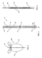
- Figure 1 is a perspective view of the web and how, according to the present invention, the zipper tape is attached to the web,
- Figure 2 is a detailed perspective drawing of the tack sealing of the zipper tape to the web, as shown in Figure 1,
- Figure 3 illustrates a typical opening style of the bag resulting from the present invention,
- Figure 4 is a cross-sectional view of the zipper tape section according to the present invention,
- Figure 5 is a cross-sectional view of the zipper tape section sealed to the web according to the present invention,
- Figure 6 is a plan view of the zipper tape, showing the cut lines and the spacing of the clear areas and the areas with a heat resistant coating, according to a first aspect of the present invention,
- Figure 7 is a cross-sectional view of a zipper resulting from the zipper tape as cut according to the first aspect of the present invention,
- Figure 8 is plan view of the zipper tape, showing the cut lines and the spacing of the clear areas and the areas with a heat resistant coating, according to a second aspect of the present invention, and
- Figure 9 is a cross-sectional view of a zipper resulting from the zipper tape as cut according to the second aspect of the present invention.
-
- Referring now to the drawings in detail wherein like numerals indicate like elements throughout the several views, one sees that Figure 1 is a perspective view of the
web 100 and how thezipper tape 10 is attached thereto.Web 100 is a planar sheet and travels in the direction indicated in Figure 1, generally toward a form fill and seal (FFS) apparatus (not shown). - Figure 2 shows the
zipper tape 10 in more detail.Zipper tape 10 includes twohalves interlocking zipper profiles 16, 18 (also see Figures 4 and 5), and is oriented transverse to the direction of travel of theweb 100. As shown in Figure 4, the leadingedges halves portions halves resistant coating halves portion 29 ofzipper tape 10 trailingzipper profiles - As shown in Figure 1,
tack sealing bar 102 is transversely oriented with respect to the direction of travel ofweb 100 and includes downwardly facingtack sealing ribs 104 periodically spaced alonglower surface 106 oftack sealing bar 102.Tack sealing ribs 104 are oriented parallel to the direction of travel ofweb 100 and form tack seals 30 (see Figure 2) between leadingedges zipper tape 10 andweb 100. These tack seals are likewise carrier seals, but typically break when the bag 200 (see Figure 3) is opened. - The
web 100 is cut, folded intosides halves zipper tape 10 in an FFS device such as that shown in US-A-6151868, and as shown in Figure 5,top bag seal 114 is formed by sealingside 110 toside 112. This results in thebag 200 as illustrated in Figure 3, which further illustrates a typical opening style ofbag 200 whereinseal 114 forms a mouth, the mouth including thezipper tape 10. - A first embodiment of
zipper tape 10 is illustrated in Figures 6 and 7.Fold cut line 50 separates half 12 fromhalf 14, whereas slitter cutlines separate halves zipper tape 10 of preceding or succeeding zippers.Leading edge 22, which is a clear area free of heat resistant coating, is formed immediately adjacent toslitter cut line 52. Likewise, leadingedge 20, which is a clear area free of heat resistant coating is formed immediately adjacent toslitter cut line 54.Areas edges Clear areas areas Areas areas fold cut line 50. - As can be seen from Figure 7, when
halves edges areas areas areas seal 70, which may be a peel seal, is formed between portions ofareas zipper profiles areas - A second embodiment of
zipper tape 10 with a similar configuration is shown in Figures 8 and 9 without theseal 70 and with different proportions to the various areas. - This configuration reduces the tendency of the leading edge of the zipper to jam as the web moves over the collar of a form fill and seal apparatus (not shown).
Claims (7)
- A zipper tape (10) comprising:a first zipper half (12) facing a second zipper half (14), said first zipper half having a leading edge (20) and a trailing edge facing a respective leading edge (22) and a respective trailing edge of said second zipper half;said first zipper half (12) and said second zipper half (14) having portions (56,58,64,66) treated with heat resistant coating (27,28); andsaid leading edge (20) of said first zipper half (12) and said leading edge (22) of said second zipper half (14) being free of heat resistant coating.
- The zipper tape (10) of claim 1, wherein a central area (62) of said first zipper half (12) faces a central area (60) of said second zipper half (14), said central areas each having a respective interlocking profile (16,18) secured thereto or formed therein, said interlocking profiles (16,18) being interlockable with each other.
- The zipper tape (10) of claim 1 or claim 2, wherein said trailing edges of said first zipper half (12) and said second zipper half (14) are treated with said heat resistant coating (27,28).
- The zipper tape (10) of any one of the preceding claims, further including a peel-seal (70) between said first zipper half (12) and said second zipper half (14) adjacent to said respective interlocking profiles (16,18).
- The zipper tape (10) of any one of the preceding claims, wherein said leading edges (20,22) are at least intermittently sealed to a web (100).
- A plastic bag (200) comprising:
a first wall (110) and a second wall (112), said first wall sealed to said second wall to form a mouth, said mouth including a zipper tape (10) according to any one of the preceding claims, sealed to said first wall and said second wall to allow selective opening and closing said mouth. - The plastic bag (200) of claim 6, wherein said leading edges (20,22) are at least intermittently sealed to at least one of said first (110) or second (112) walls.
Applications Claiming Priority (2)
| Application Number | Priority Date | Filing Date | Title |
|---|---|---|---|
| US09/564,907 US6350058B1 (en) | 2000-05-04 | 2000-05-04 | Partially secured four flange zipper strip for transverse direction |
| US564907 | 2000-05-04 |
Publications (3)
| Publication Number | Publication Date |
|---|---|
| EP1151930A2 true EP1151930A2 (en) | 2001-11-07 |
| EP1151930A3 EP1151930A3 (en) | 2002-09-11 |
| EP1151930B1 EP1151930B1 (en) | 2004-03-10 |
Family
ID=24256384
Family Applications (1)
| Application Number | Title | Priority Date | Filing Date |
|---|---|---|---|
| EP01304055A Expired - Lifetime EP1151930B1 (en) | 2000-05-04 | 2001-05-03 | Zipper strip |
Country Status (9)
| Country | Link |
|---|---|
| US (1) | US6350058B1 (en) |
| EP (1) | EP1151930B1 (en) |
| JP (1) | JP2001315805A (en) |
| AT (1) | ATE261376T1 (en) |
| AU (1) | AU740808B1 (en) |
| BR (1) | BR0101663A (en) |
| CA (1) | CA2345824A1 (en) |
| DE (1) | DE60102256T2 (en) |
| MX (1) | MXPA01004459A (en) |
Families Citing this family (14)
| Publication number | Priority date | Publication date | Assignee | Title |
|---|---|---|---|---|
| US7040810B2 (en) * | 2002-03-26 | 2006-05-09 | Mark Steele | Flexible package with a transverse access panel device |
| US20040078938A1 (en) * | 2002-10-23 | 2004-04-29 | Pawloski James C. | Closure device for a reclosable pouch |
| US7036988B2 (en) * | 2003-02-19 | 2006-05-02 | Illinois Tool Works Inc. | Zipper for vacuum storage bag |
| US7674039B2 (en) * | 2003-02-19 | 2010-03-09 | Illinois Tool Works Inc. | Reclosable vacuum storage bag having flat resealable means |
| USD549594S1 (en) | 2003-03-25 | 2007-08-28 | Mark Steele | Side access flexible package |
| USD621280S1 (en) | 2003-03-25 | 2010-08-10 | Mark Steele | Side access flexible package |
| US20050069227A1 (en) * | 2003-09-29 | 2005-03-31 | Mark Steele | Flexible package having integrated slit member |
| JP4801328B2 (en) * | 2004-06-04 | 2011-10-26 | 出光ユニテック株式会社 | CHUCK TAPE, PACKAGING BAG WITH CHUCK TAPE, AND METHOD FOR MANUFACTURING PACKAGING BAG WITH CHUCK TAPE |
| US7419300B2 (en) | 2004-06-16 | 2008-09-02 | S.C. Johnson Home Storage, Inc. | Pouch having fold-up handles |
| US20100086238A1 (en) * | 2008-10-02 | 2010-04-08 | Victoria Sprehe | Bag with a pocket for a thermal insulating material and method of making same |
| US20100226600A1 (en) * | 2009-02-26 | 2010-09-09 | Mark Steele | Package with releasable film access opening |
| US8128546B2 (en) | 2009-05-07 | 2012-03-06 | Cmd Corporation | In-line method for securing a closure system onto a discrete pouch |
| US20100284633A1 (en) * | 2009-05-07 | 2010-11-11 | Cmd Corporation | Discrete pouch having a closure system secured thereto |
| US8128545B2 (en) * | 2009-05-07 | 2012-03-06 | Cmd Corporation | Machine for securing a closure system onto a discrete pouch |
Citations (2)
| Publication number | Priority date | Publication date | Assignee | Title |
|---|---|---|---|---|
| US4909017A (en) | 1989-07-28 | 1990-03-20 | Minigrip, Inc. | Reclosable bag material, method and apparatus |
| US6065872A (en) | 1999-02-04 | 2000-05-23 | Illinois Tool Works Inc. | Pinch and pull open reclosable bag and zipper therefor |
Family Cites Families (6)
| Publication number | Priority date | Publication date | Assignee | Title |
|---|---|---|---|---|
| AT268986B (en) * | 1965-12-11 | 1969-02-25 | Minigrip Europ Akt | Bag made from weldable plastic film |
| US5100246A (en) * | 1990-10-09 | 1992-03-31 | Illinois Tool Works Inc. | Pull bead and guide rails for easy open flexible containers |
| US5152613A (en) * | 1991-03-22 | 1992-10-06 | Mobil Oil Corporation | Plastic film zipper bag having straightened heat seals |
| US5470156A (en) * | 1994-04-11 | 1995-11-28 | Reynolds Consumer Products, Inc. | Closure arrangement having a peelable seal |
| CA2203086A1 (en) * | 1996-04-29 | 1997-10-29 | Illinois Tool Works Inc. | Controlled peel seal with indicating feature |
| CA2269358C (en) * | 1998-05-21 | 2005-04-12 | Illinois Tool Works Inc. | Transverse direction zipper tape |
-
2000
- 2000-05-04 US US09/564,907 patent/US6350058B1/en not_active Expired - Fee Related
-
2001
- 2001-05-02 BR BR0101663-6A patent/BR0101663A/en not_active IP Right Cessation
- 2001-05-02 JP JP2001135370A patent/JP2001315805A/en active Pending
- 2001-05-03 MX MXPA01004459A patent/MXPA01004459A/en active IP Right Grant
- 2001-05-03 AT AT01304055T patent/ATE261376T1/en not_active IP Right Cessation
- 2001-05-03 CA CA002345824A patent/CA2345824A1/en not_active Abandoned
- 2001-05-03 DE DE60102256T patent/DE60102256T2/en not_active Expired - Fee Related
- 2001-05-03 AU AU42056/01A patent/AU740808B1/en not_active Ceased
- 2001-05-03 EP EP01304055A patent/EP1151930B1/en not_active Expired - Lifetime
Patent Citations (3)
| Publication number | Priority date | Publication date | Assignee | Title |
|---|---|---|---|---|
| US4909017A (en) | 1989-07-28 | 1990-03-20 | Minigrip, Inc. | Reclosable bag material, method and apparatus |
| US4909017B1 (en) | 1989-07-28 | 1999-02-09 | Minigrip Inc | Reclosable bag material method and apparatus |
| US6065872A (en) | 1999-02-04 | 2000-05-23 | Illinois Tool Works Inc. | Pinch and pull open reclosable bag and zipper therefor |
Also Published As
| Publication number | Publication date |
|---|---|
| CA2345824A1 (en) | 2001-11-04 |
| JP2001315805A (en) | 2001-11-13 |
| MXPA01004459A (en) | 2005-06-30 |
| ATE261376T1 (en) | 2004-03-15 |
| AU740808B1 (en) | 2001-11-15 |
| EP1151930B1 (en) | 2004-03-10 |
| DE60102256T2 (en) | 2004-07-22 |
| BR0101663A (en) | 2001-12-18 |
| DE60102256D1 (en) | 2004-04-15 |
| US6350058B1 (en) | 2002-02-26 |
| EP1151930A3 (en) | 2002-09-11 |
Similar Documents
| Publication | Publication Date | Title |
|---|---|---|
| EP1151930B1 (en) | Zipper strip | |
| EP0982117B1 (en) | Intermediate Layer for Fastener Tape | |
| EP1194339B1 (en) | System for manufacturing of a resealable package having slider device and tamper-evident structure, and methods of manufacturing thereof | |
| EP1099636B1 (en) | Methods of manufacturing reclosable package having a slider device | |
| US6327754B1 (en) | Fastener with slider thereon for use in manufacturing recloseable bags | |
| US6257763B1 (en) | Tamper evident zipper slider | |
| US7886412B2 (en) | Pouch and airtight resealable closure mechanism therefor | |
| EP1123796B1 (en) | Methods of manufacturing reclosable packages using transverse closure and slider applicator | |
| US6962439B2 (en) | Leak resistant tamper evident reclosable plastic bag | |
| EP1129955A2 (en) | Reclosable package having slider device and tamper-evident structure | |
| US6928791B2 (en) | Process and apparatus for forming packaging bags with a fastener | |
| EP1295797B1 (en) | Form, fill and seal packaging method and apparatus | |
| US5026563A (en) | Zippered closure for thermoformed package | |
| EP1858361B1 (en) | Childproof reclosable bag | |
| US8549713B2 (en) | Zippered security bag | |
| EP1248732B1 (en) | Reclosable package having slider device and tamper-evident structure | |
| EP1132311A2 (en) | Reclosable, package having zipper closure, slider device and tampers-evident structure and methods | |
| US20250361062A1 (en) | Flexible enclosure having a seal and method and system for making the same | |
| US11845587B2 (en) | Resealable bag enclosure | |
| US20020081043A1 (en) | Plastic bag with easy open and easy close profiles |
Legal Events
| Date | Code | Title | Description |
|---|---|---|---|
| PUAI | Public reference made under article 153(3) epc to a published international application that has entered the european phase |
Free format text: ORIGINAL CODE: 0009012 |
|
| AK | Designated contracting states |
Kind code of ref document: A2 Designated state(s): AT BE CH CY DE DK ES FI FR GB GR IE IT LI LU MC NL PT SE TR |
|
| AX | Request for extension of the european patent |
Free format text: AL;LT;LV;MK;RO;SI |
|
| PUAL | Search report despatched |
Free format text: ORIGINAL CODE: 0009013 |
|
| AK | Designated contracting states |
Kind code of ref document: A3 Designated state(s): AT BE CH CY DE DK ES FI FR GB GR IE IT LI LU MC NL PT SE TR |
|
| AX | Request for extension of the european patent |
Free format text: AL;LT;LV;MK;RO;SI |
|
| REG | Reference to a national code |
Ref country code: GB Ref legal event code: FG4D |
|
| 17P | Request for examination filed |
Effective date: 20030221 |
|
| AKX | Designation fees paid |
Designated state(s): AT BE CH CY DE DK ES FI FR GB GR IE IT LI LU MC NL PT SE TR |
|
| GRAP | Despatch of communication of intention to grant a patent |
Free format text: ORIGINAL CODE: EPIDOSNIGR1 |
|
| GRAS | Grant fee paid |
Free format text: ORIGINAL CODE: EPIDOSNIGR3 |
|
| GRAA | (expected) grant |
Free format text: ORIGINAL CODE: 0009210 |
|
| AK | Designated contracting states |
Kind code of ref document: B1 Designated state(s): AT BE CH CY DE DK ES FI FR GB GR IE IT LI LU MC NL PT SE TR |
|
| PG25 | Lapsed in a contracting state [announced via postgrant information from national office to epo] |
Ref country code: TR Free format text: LAPSE BECAUSE OF FAILURE TO SUBMIT A TRANSLATION OF THE DESCRIPTION OR TO PAY THE FEE WITHIN THE PRESCRIBED TIME-LIMIT Effective date: 20040310 Ref country code: NL Free format text: LAPSE BECAUSE OF FAILURE TO SUBMIT A TRANSLATION OF THE DESCRIPTION OR TO PAY THE FEE WITHIN THE PRESCRIBED TIME-LIMIT Effective date: 20040310 Ref country code: LI Free format text: LAPSE BECAUSE OF FAILURE TO SUBMIT A TRANSLATION OF THE DESCRIPTION OR TO PAY THE FEE WITHIN THE PRESCRIBED TIME-LIMIT Effective date: 20040310 Ref country code: IT Free format text: LAPSE BECAUSE OF FAILURE TO SUBMIT A TRANSLATION OF THE DESCRIPTION OR TO PAY THE FEE WITHIN THE PRESCRIBED TIME-LIMIT;WARNING: LAPSES OF ITALIAN PATENTS WITH EFFECTIVE DATE BEFORE 2007 MAY HAVE OCCURRED AT ANY TIME BEFORE 2007. THE CORRECT EFFECTIVE DATE MAY BE DIFFERENT FROM THE ONE RECORDED. Effective date: 20040310 Ref country code: FI Free format text: LAPSE BECAUSE OF FAILURE TO SUBMIT A TRANSLATION OF THE DESCRIPTION OR TO PAY THE FEE WITHIN THE PRESCRIBED TIME-LIMIT Effective date: 20040310 Ref country code: CY Free format text: LAPSE BECAUSE OF FAILURE TO SUBMIT A TRANSLATION OF THE DESCRIPTION OR TO PAY THE FEE WITHIN THE PRESCRIBED TIME-LIMIT Effective date: 20040310 Ref country code: CH Free format text: LAPSE BECAUSE OF FAILURE TO SUBMIT A TRANSLATION OF THE DESCRIPTION OR TO PAY THE FEE WITHIN THE PRESCRIBED TIME-LIMIT Effective date: 20040310 Ref country code: BE Free format text: LAPSE BECAUSE OF FAILURE TO SUBMIT A TRANSLATION OF THE DESCRIPTION OR TO PAY THE FEE WITHIN THE PRESCRIBED TIME-LIMIT Effective date: 20040310 Ref country code: AT Free format text: LAPSE BECAUSE OF FAILURE TO SUBMIT A TRANSLATION OF THE DESCRIPTION OR TO PAY THE FEE WITHIN THE PRESCRIBED TIME-LIMIT Effective date: 20040310 |
|
| REG | Reference to a national code |
Ref country code: CH Ref legal event code: EP |
|
| REG | Reference to a national code |
Ref country code: IE Ref legal event code: FG4D |
|
| REF | Corresponds to: |
Ref document number: 60102256 Country of ref document: DE Date of ref document: 20040415 Kind code of ref document: P |
|
| PG25 | Lapsed in a contracting state [announced via postgrant information from national office to epo] |
Ref country code: LU Free format text: LAPSE BECAUSE OF NON-PAYMENT OF DUE FEES Effective date: 20040503 |
|
| PG25 | Lapsed in a contracting state [announced via postgrant information from national office to epo] |
Ref country code: IE Free format text: LAPSE BECAUSE OF NON-PAYMENT OF DUE FEES Effective date: 20040504 |
|
| PG25 | Lapsed in a contracting state [announced via postgrant information from national office to epo] |
Ref country code: MC Free format text: LAPSE BECAUSE OF NON-PAYMENT OF DUE FEES Effective date: 20040531 |
|
| PG25 | Lapsed in a contracting state [announced via postgrant information from national office to epo] |
Ref country code: SE Free format text: LAPSE BECAUSE OF FAILURE TO SUBMIT A TRANSLATION OF THE DESCRIPTION OR TO PAY THE FEE WITHIN THE PRESCRIBED TIME-LIMIT Effective date: 20040610 Ref country code: GR Free format text: LAPSE BECAUSE OF FAILURE TO SUBMIT A TRANSLATION OF THE DESCRIPTION OR TO PAY THE FEE WITHIN THE PRESCRIBED TIME-LIMIT Effective date: 20040610 Ref country code: DK Free format text: LAPSE BECAUSE OF FAILURE TO SUBMIT A TRANSLATION OF THE DESCRIPTION OR TO PAY THE FEE WITHIN THE PRESCRIBED TIME-LIMIT Effective date: 20040610 |
|
| PG25 | Lapsed in a contracting state [announced via postgrant information from national office to epo] |
Ref country code: ES Free format text: LAPSE BECAUSE OF FAILURE TO SUBMIT A TRANSLATION OF THE DESCRIPTION OR TO PAY THE FEE WITHIN THE PRESCRIBED TIME-LIMIT Effective date: 20040621 |
|
| NLV1 | Nl: lapsed or annulled due to failure to fulfill the requirements of art. 29p and 29m of the patents act | ||
| REG | Reference to a national code |
Ref country code: CH Ref legal event code: PL |
|
| ET | Fr: translation filed | ||
| PLBE | No opposition filed within time limit |
Free format text: ORIGINAL CODE: 0009261 |
|
| STAA | Information on the status of an ep patent application or granted ep patent |
Free format text: STATUS: NO OPPOSITION FILED WITHIN TIME LIMIT |
|
| REG | Reference to a national code |
Ref country code: IE Ref legal event code: MM4A |
|
| 26N | No opposition filed |
Effective date: 20041213 |
|
| PGFP | Annual fee paid to national office [announced via postgrant information from national office to epo] |
Ref country code: GB Payment date: 20050427 Year of fee payment: 5 |
|
| PGFP | Annual fee paid to national office [announced via postgrant information from national office to epo] |
Ref country code: FR Payment date: 20050517 Year of fee payment: 5 |
|
| PGFP | Annual fee paid to national office [announced via postgrant information from national office to epo] |
Ref country code: DE Payment date: 20050630 Year of fee payment: 5 |
|
| PG25 | Lapsed in a contracting state [announced via postgrant information from national office to epo] |
Ref country code: GB Free format text: LAPSE BECAUSE OF NON-PAYMENT OF DUE FEES Effective date: 20060503 |
|
| PG25 | Lapsed in a contracting state [announced via postgrant information from national office to epo] |
Ref country code: DE Free format text: LAPSE BECAUSE OF NON-PAYMENT OF DUE FEES Effective date: 20061201 |
|
| GBPC | Gb: european patent ceased through non-payment of renewal fee |
Effective date: 20060503 |
|
| REG | Reference to a national code |
Ref country code: FR Ref legal event code: ST Effective date: 20070131 |
|
| PG25 | Lapsed in a contracting state [announced via postgrant information from national office to epo] |
Ref country code: PT Free format text: LAPSE BECAUSE OF NON-PAYMENT OF DUE FEES Effective date: 20040810 |
|
| PG25 | Lapsed in a contracting state [announced via postgrant information from national office to epo] |
Ref country code: FR Free format text: LAPSE BECAUSE OF NON-PAYMENT OF DUE FEES Effective date: 20060531 |