EP1151917A2 - Skin/bulkhead structure - Google Patents
Skin/bulkhead structure Download PDFInfo
- Publication number
- EP1151917A2 EP1151917A2 EP01303986A EP01303986A EP1151917A2 EP 1151917 A2 EP1151917 A2 EP 1151917A2 EP 01303986 A EP01303986 A EP 01303986A EP 01303986 A EP01303986 A EP 01303986A EP 1151917 A2 EP1151917 A2 EP 1151917A2
- Authority
- EP
- European Patent Office
- Prior art keywords
- skin
- bulkhead
- barrel
- connecting member
- shaped
- Prior art date
- Legal status (The legal status is an assumption and is not a legal conclusion. Google has not performed a legal analysis and makes no representation as to the accuracy of the status listed.)
- Granted
Links
Images


Classifications
-
- B—PERFORMING OPERATIONS; TRANSPORTING
- B64—AIRCRAFT; AVIATION; COSMONAUTICS
- B64C—AEROPLANES; HELICOPTERS
- B64C1/00—Fuselages; Constructional features common to fuselages, wings, stabilising surfaces or the like
- B64C1/06—Frames; Stringers; Longerons ; Fuselage sections
- B64C1/10—Bulkheads
Definitions
- the present invention relates to a skin/bulkhead structure comprising a barrel-shaped skin made of a fiber-reinforced composite and a pressure bulkhead connected to an opening of the barrel-shaped skin.
- Pressure bulkheads which are installed in front and back of a pressurized cabin of aircrafts, etc., are classified to spherical panels and flat panels.
- the spherical panels are often used as an aft pressure bulkhead.
- the spherical panels are generally composed of a stiffened spherical plate, and a pressure is applied thereto as membrane force.
- the spherical panels are advantageous in high structural efficiency and small weight penalty, however, it necessitates high production cost and useless, excessive spaces.
- the flat panels are desirably used as the pressure bulkhead from the viewpoint of space-saving.
- the flat panels are generally composed of a flat plate stiffened by thick beams, and they receive an applied pressure as bending moment. The flat panels have a remarkably simple composition and high space efficiency.
- the pressure bulkhead is demanded to be connected to a barrel-shaped skin with high reliability.
- the pressure bulkhead has been connected to the barrel-shaped skin by such a method that comprises the steps of: connecting marginal portion of the pressure bulkhead to the barrel-shaped skin by rivets, adhesion, etc.; and providing complicated sealing to prevent the body from air-leaking.
- this method has suffered disadvantages of increased production cost and heavy weight.
- a light, reliable skin/bulkhead structure comprising a barrel-shaped skin and a pressure bulkhead can be produced with excellent space efficiency and reduced production cost if the pressure bulkhead is connected to the barrel-shaped skin by a combination of mechanical connection and adhesive connection.
- the present invention has been accomplished by the finding.
- a skin/bulkhead structure of the present invention comprises a barrel-shaped skin and a pressure bulkhead composed of a stiffening member and a bulkhead skin, wherein an end of the stiffening member is mechanically connected to an opening of the barrel-shaped skin through a first connecting member and marginal portion of the bulkhead skin is adhesive-connected to the opening through a second connecting member, the barrel-shaped skin, the stiffening member, the bulkhead skin, the first connecting member and the second connecting member being each made of a fiber-reinforced composite.
- the opening of the barrel-shaped skin has an edge portion expanded over the pressure bulkhead, and the end of the stiffening member is mechanically connected to the edge portion.
- the bulkhead skin is preferably a flat plate in shape, and the stiffening member preferably has an I-shaped cross section.
- the second connecting member is preferably a ring in shape, and a cross section thereof is preferably in L-shape.
- Fig. 1 partially shows an embodiment of a skin/bulkhead structure according to the present invention.
- Fig. 2 is an enlarged, partial perspective view showing the skin/bulkhead structure of Fig. 1 where a barrel-shaped skin 2 is not shown, and
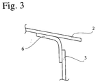
- Fig. 3 is a partial cross sectional view showing the same taken along the line A-A.
- the skin/bulkhead structure 1 comprises a barrel-shaped skin 2 and a pressure bulkhead connected to an opening thereof.
- the pressure bulkhead shown in Fig. 1 is composed of stiffening members and a bulkhead skin 3.
- main beams 4 and sub-beams 5 are used as the stiffening members.
- main beams 4 and sub-beams 5 are used as the stiffening members.
- ends of the main beams 4 and the sub-beams 5 are mechanically connected to the opening of the barrel-shaped skin 2 through main clips 7 and sub-clips 8 used as first connecting members.
- Marginal portion of the bulkhead skin 3 is adhesive-connected to the opening of the barrel-shaped skin 2 through a second connecting member 6.
- Intersections of the main beams 4 and the sub-beams 5 may be strengthened by angle joints 9, etc., if necessary.
- the barrel-shaped skin, the stiffening member, the bulkhead skin, the first connecting member and the second connecting member used in the present invention are each made of a fiber-reinforced composite.
- the fiber-reinforced composite may be a reinforcing fiber such as a carbon fiber, a glass fiber, an aramid fiber, etc. impregnated with a thermosetting resin or a thermoplastic resin.
- the thermosetting resin may be an epoxy resin, a bismaleimide resin, a phenol resin, etc.
- the thermoplastic resin may be PEEK, nylon 6, nylon 66, polyethylene terephthalate, etc.
- Preferred as the thermosetting resin is an epoxy resin
- preferred as the thermoplastic resin is nylon.
- Ratio of the resin to the reinforcing fiber in the fiber-reinforced composite may be appropriately controlled.
- the barrel-shaped skin, the stiffening member, the bulkhead skin, the first connecting member and the second connecting member are preferably made of the same fiber-reinforced composite, although they may be made of different composites.
- Load applied to the pressure bulkhead reaches the barrel-shaped skin through the following two pathways: (1) the bulkhead skin - the stiffening member - the first connecting member - the barrel-shaped skin; and (2) the bulkhead skin - the second connecting member - the barrel-shaped skin.
- the first connecting member is not particularly limited, may be a fastener of FRP, a bolt of a stainless steel or a metal, etc.
- the first connecting member is preferably made of titanium, which is light in weight and excellent in corrosion resistance.
- the bulkhead skin and the barrel-shaped skin are assembled by the adhesive-connection without complicated sealing, thereby reducing weight and production cost of the skin/bulkhead structure.
- an adhesive such as an epoxy resin is preferably used.
- a plurality of the adhesives may be used in combination.
- the adhesive-connection is preferably carried out under a pressure of 0.1 to 2 kg/cm 2 .
- Thickness of the barrel-shaped skin is not particularly limited and it may be selected depending on use of the skin/bulkhead structure.
- Specific shape of the barrel-shaped skin may be a cylinder shape, an elliptic cylinder shape, a pipe shape having a comer portion, etc., it being also not particularly limited.
- the pressure bulkhead is composed of the bulkhead skin and the stiffening member arranged thereon.
- the bulkhead skin is preferably a flat plate in shape from the viewpoint of space efficiency.
- the bulkhead skin preferably has thickness of 0.8 to 2.3 mm in the case of using it for small aircrafts.
- the stiffening member may be fixed to the bulkhead skin by adhesion, a rivet, etc.
- the stiffening member is preferably fixed to the bulkhead skin by adhesion.
- the stiffening members are generally arranged in lattice pattern on the bulkhead skin, positional relationships therebetween and number thereof may be properly changed. It is preferable that the opening of the barrel-shaped skin has an edge portion expanded over the pressure bulkhead to be not pressurized, and the end of the stiffening member is mechanically connected to the edge portion.
- the main beams 4 and the sub-beams 5 correspond to the above-mentioned stiffening member.
- the main beams 4 have an I-shaped cross section
- the sub-beams 5 separated by the main beams 4 have a C-shaped cross section.
- the stiffening member used in the present invention may have a cross section of C-shape, I-shape, J-shape, T-shape, etc.
- the stiffening member preferably has an I-shaped cross section to avoid twisting or buckling.
- the second connecting member used in the present invention is preferably a ring in shape. Further, a cross section thereof is preferably an L-shape as the second connecting member 6 shown in Figs. 2 and 3.
- the main clips 7 and the sub-clips 8 are used as the first connecting member.
- the first connecting member having an L-shaped cross section such as shown in Figs. 1 and 2 is preferably used in this invention to mechanically connect the stiffening member to the barrel-shaped skin with ease.
- a skin/bulkhead structure of the present invention comprises a barrel-shaped skin made of a fiber-reinforced composite and a pressure bulkhead connected to an opening thereof.
- the skin/bulkhead structure is reliable, light in weight and excellent in space efficiency, and can be produced with reduced production cost.
- the skin/bulkhead structure can be preferably used for aircraft bodies.
Landscapes
- Engineering & Computer Science (AREA)
- Mechanical Engineering (AREA)
- Aviation & Aerospace Engineering (AREA)
- Laminated Bodies (AREA)
- Connection Of Plates (AREA)
- Pressure Welding/Diffusion-Bonding (AREA)
- Joining Of Building Structures In Genera (AREA)
Abstract
Description
Claims (7)
- A skin/bulkhead structure comprising a barrel-shaped skin (2) and a pressure bulkhead composed of a stiffening member (4,5) and a bulkhead skin (3), wherein an end of said stiffening member is mechanically connected to an opening of said barrel-shaped skin through a first connecting member (7,8) and a marginal portion of said bulkhead skin is adhesive-connected to said opening through a second connecting member (6), said barrel-shaped skin, said stiffening member, said bulkhead skin, said first connecting member and said second connecting member being each made of a fiber-reinforced composite.
- The skin/bulkhead structure according to claim 1, wherein said opening of said barrel-shaped skin (2) has an edge portion expanded over said pressure bulkhead, and said end of said stiffening member (4,5) is mechanically connected to said edge portion.
- The skin/bulkhead structure according to claim 1 or 2, wherein said bulkhead skin (3) is a flat plate in shape.
- The skin/bulkhead structure according to any one of claims 1 to 3, wherein said stiffening member (4,5) has an I-shaped cross section.
- The skin/bulkhead structure according to any one of claims 1 to 4, wherein said second connecting member (6) is a ring in shape.
- The skin/bulkhead structure according to any one of claims 1 to 5, wherein said second connecting member (6) has an L-shaped cross section.
- An aircraft having a skin/bulkhead structure as claimed in any preceding claim.
Applications Claiming Priority (2)
| Application Number | Priority Date | Filing Date | Title |
|---|---|---|---|
| JP2000132682A JP3997047B2 (en) | 2000-05-01 | 2000-05-01 | Bonding structure of skin and pressure bulkhead |
| JP2000132682 | 2000-05-01 |
Publications (3)
| Publication Number | Publication Date |
|---|---|
| EP1151917A2 true EP1151917A2 (en) | 2001-11-07 |
| EP1151917A3 EP1151917A3 (en) | 2002-12-18 |
| EP1151917B1 EP1151917B1 (en) | 2004-03-17 |
Family
ID=18641328
Family Applications (1)
| Application Number | Title | Priority Date | Filing Date |
|---|---|---|---|
| EP01303986A Expired - Lifetime EP1151917B1 (en) | 2000-05-01 | 2001-05-01 | Skin/bulkhead structure |
Country Status (4)
| Country | Link |
|---|---|
| US (1) | US6478254B2 (en) |
| EP (1) | EP1151917B1 (en) |
| JP (1) | JP3997047B2 (en) |
| DE (1) | DE60102315T2 (en) |
Cited By (3)
| Publication number | Priority date | Publication date | Assignee | Title |
|---|---|---|---|---|
| WO2008000670A3 (en) * | 2006-06-26 | 2008-02-21 | Airbus Gmbh | Pressure bulkhead for an aerospace fuselage |
| WO2009085041A1 (en) * | 2007-12-27 | 2009-07-09 | General Electric Company | Flexible wind blade root bulkhead flange |
| FR3049927A1 (en) * | 2016-04-07 | 2017-10-13 | Airbus Operations Sas | AIRCRAFT TRONCON COMPRISING A PRESSURIZATION PARTITION |
Families Citing this family (17)
| Publication number | Priority date | Publication date | Assignee | Title |
|---|---|---|---|---|
| US20040126193A1 (en) * | 2002-11-01 | 2004-07-01 | Jeff Moreau | Carbon fiber re-enforced composite sheet piling segments |
| US20040141815A1 (en) * | 2002-11-01 | 2004-07-22 | Jeff Moreau | Fiber re-enforcement of joints and corners of composite sheet piling segments |
| US9359061B2 (en) * | 2005-10-31 | 2016-06-07 | The Boeing Company | Compliant stiffener for aircraft fuselage |
| US20080179459A1 (en) * | 2007-01-30 | 2008-07-31 | Airbus Espana, S.L. | Pressure bulkhead made of composite material for an aircraft |
| DE102007044388B4 (en) * | 2007-09-18 | 2012-08-02 | Airbus Operations Gmbh | Pressure bulkhead and method for dividing an aircraft or spacecraft |
| EP2259965B1 (en) * | 2008-03-31 | 2013-01-09 | Honda Patents & Technologies North America, LLC | Pressure bulkhead for aircraft |
| US9108716B2 (en) * | 2012-11-06 | 2015-08-18 | The Boeing Company | Aircraft having a recessed cavity in an aft pressure bulkhead wall surface and a galley moved rearwardly into the recessed cavity increasing floor space in front of the galley |
| US10189578B2 (en) * | 2013-06-12 | 2019-01-29 | The Boeing Company | Self-balancing pressure bulkhead |
| US9199713B2 (en) * | 2013-07-08 | 2015-12-01 | The Boeing Company | Pressure panels |
| US9187168B2 (en) | 2013-07-30 | 2015-11-17 | The Boeing Company | Natural-path tearstraps and stiffeners for spherical composite pressure bulkheads |
| EP3059156B1 (en) * | 2015-02-23 | 2020-04-01 | Airbus Operations, S.L. | Flat kinked rear pressure bulkhead |
| DE102015111160B4 (en) * | 2015-07-09 | 2018-09-06 | Airbus Operations Gmbh | Hull structure and method for making a hull structure |
| US10173765B2 (en) * | 2016-04-07 | 2019-01-08 | The Boeing Company | Pressure bulkhead apparatus |
| US10926857B2 (en) * | 2016-06-17 | 2021-02-23 | The Boeing Company | Pressurized bulkhead |
| CN108216575A (en) * | 2016-12-15 | 2018-06-29 | 贾海亮 | A kind of structure for preventing nacelle pressure release from fluid cone occur |
| EP3447280B1 (en) | 2017-08-21 | 2020-12-16 | LM Wind Power International Technology II ApS | A bulkhead unit, a wind turbine blade comprising the bulkhead unit, and methods of assembling and installing the bulkhead unit |
| CN110450904A (en) * | 2019-08-29 | 2019-11-15 | 广船国际有限公司 | The connection structure of ship crossbeam and siding |
Family Cites Families (10)
| Publication number | Priority date | Publication date | Assignee | Title |
|---|---|---|---|---|
| US2405918A (en) * | 1944-05-13 | 1946-08-13 | Budd Edward G Mfg Co | Airplane construction |
| US3425333A (en) * | 1967-09-05 | 1969-02-04 | Millard A Wachter | Pressure control valve for aircraft |
| GB2134059B (en) * | 1983-01-25 | 1986-06-25 | Westland Plc | Composite helicopter fuselage |
| DE3923871A1 (en) * | 1989-02-28 | 1991-01-31 | Dornier Luftfahrt | PRINT FRAME |
| FR2649665B1 (en) * | 1989-07-12 | 1991-11-08 | Airbus Ind | LARGE CAPACITY FUSELAGE FOR AIRCRAFT |
| DE19652172C2 (en) * | 1996-12-14 | 1998-09-17 | Daimler Benz Aerospace Airbus | Pressure frame for an aircraft fuselage |
| JPH10258463A (en) * | 1997-03-19 | 1998-09-29 | Fuji Heavy Ind Ltd | Composite small bone and molding method |
| AT405813B (en) * | 1997-11-10 | 1999-11-25 | Fischer Adv Components Gmbh | PRESSURE BOARD, IN PARTICULAR FOR AIRCRAFT |
| US5899412A (en) * | 1997-12-19 | 1999-05-04 | Northrop Grumman Corporation | Aircraft pressure containment assembly module |
| US6213426B1 (en) * | 1999-07-09 | 2001-04-10 | The Boeing Company | Monolithic structure with redundant load paths |
-
2000
- 2000-05-01 JP JP2000132682A patent/JP3997047B2/en not_active Expired - Lifetime
-
2001
- 2001-04-26 US US09/842,159 patent/US6478254B2/en not_active Expired - Lifetime
- 2001-05-01 DE DE60102315T patent/DE60102315T2/en not_active Expired - Lifetime
- 2001-05-01 EP EP01303986A patent/EP1151917B1/en not_active Expired - Lifetime
Cited By (8)
| Publication number | Priority date | Publication date | Assignee | Title |
|---|---|---|---|---|
| WO2008000670A3 (en) * | 2006-06-26 | 2008-02-21 | Airbus Gmbh | Pressure bulkhead for an aerospace fuselage |
| JP2009541131A (en) * | 2006-06-26 | 2009-11-26 | エアバス・オペレーションズ・ゲーエムベーハー | Pressure bulkhead for aerospace aircraft |
| US8033503B2 (en) | 2006-06-26 | 2011-10-11 | Airbus Deutschland Gmbh | Pressure bulkhead for an aerospace fuselage |
| RU2438919C2 (en) * | 2006-06-26 | 2012-01-10 | Эйрбас Оперейшнз Гмбх | Sealed frame for aircraft fuselage |
| EP2428444A1 (en) * | 2006-06-26 | 2012-03-14 | Airbus Operations GmbH | Pressure bulkhead for an aerospace fuselage |
| CN102167151B (en) * | 2006-06-26 | 2013-08-21 | 空中客车德国有限公司 | Pressure bulkhead for an aerospace fuselage |
| WO2009085041A1 (en) * | 2007-12-27 | 2009-07-09 | General Electric Company | Flexible wind blade root bulkhead flange |
| FR3049927A1 (en) * | 2016-04-07 | 2017-10-13 | Airbus Operations Sas | AIRCRAFT TRONCON COMPRISING A PRESSURIZATION PARTITION |
Also Published As
| Publication number | Publication date |
|---|---|
| EP1151917B1 (en) | 2004-03-17 |
| DE60102315T2 (en) | 2004-08-05 |
| DE60102315D1 (en) | 2004-04-22 |
| EP1151917A3 (en) | 2002-12-18 |
| US20010035118A1 (en) | 2001-11-01 |
| US6478254B2 (en) | 2002-11-12 |
| JP3997047B2 (en) | 2007-10-24 |
| JP2001315696A (en) | 2001-11-13 |
Similar Documents
| Publication | Publication Date | Title |
|---|---|---|
| EP1151917B1 (en) | Skin/bulkhead structure | |
| US8226870B2 (en) | Pressure bulkhead made of composite material for an aircraft | |
| US8434716B2 (en) | Compliant crown panel for an aircraft | |
| EP2137063B1 (en) | Attachment arrangement for attaching a component to the fuselage of an aircraft, aircraft and method for constructing an attachment arrangement | |
| US20050263645A1 (en) | Structural panels for use in aircraft fuselages and other structures | |
| EP2813425A1 (en) | Self-balancing pressure bulkhead | |
| US8505851B2 (en) | Profile comprising at least one hollow profile section | |
| EP3838741B1 (en) | Longitudinal beam joint for a pressure deck assembly | |
| JP5808112B2 (en) | Composite structure and aircraft main wing provided with the same | |
| US5171099A (en) | Apparatus to attach a sandwich panel | |
| US20070264472A1 (en) | Sandwich Panel and a Method of Producing a Sandwich Panel | |
| US8511034B2 (en) | Hybrid contoured load-spreading washer | |
| EP3450302B1 (en) | Energy-absorbing under-floor airframe | |
| EP2098448A1 (en) | Composite pressure bulkhead for aircraft | |
| US11572907B2 (en) | Shear pin for panel structural support | |
| US8528874B2 (en) | Hybrid contoured load-spreading washer | |
| US20110073711A1 (en) | Joining of structural aircraft elements | |
| EP3636539A1 (en) | Panel for an aircraft | |
| CA3014235C (en) | Energy-absorbing under-floor airframe | |
| CN117537672A (en) | Fairing for carrier rocket | |
| CN117401147A (en) | Fuselage sections for aircraft and aircraft |
Legal Events
| Date | Code | Title | Description |
|---|---|---|---|
| PUAI | Public reference made under article 153(3) epc to a published international application that has entered the european phase |
Free format text: ORIGINAL CODE: 0009012 |
|
| AK | Designated contracting states |
Kind code of ref document: A2 Designated state(s): AT BE CH CY DE DK ES FI FR GB GR IE IT LI LU MC NL PT SE TR |
|
| AX | Request for extension of the european patent |
Free format text: AL;LT;LV;MK;RO;SI |
|
| PUAL | Search report despatched |
Free format text: ORIGINAL CODE: 0009013 |
|
| AK | Designated contracting states |
Kind code of ref document: A3 Designated state(s): AT BE CH CY DE DK ES FI FR GB GR IE IT LI LU MC NL PT SE TR |
|
| AX | Request for extension of the european patent |
Free format text: AL;LT;LV;MK;RO;SI |
|
| 17P | Request for examination filed |
Effective date: 20030617 |
|
| GRAP | Despatch of communication of intention to grant a patent |
Free format text: ORIGINAL CODE: EPIDOSNIGR1 |
|
| AKX | Designation fees paid |
Designated state(s): DE FR GB |
|
| GRAS | Grant fee paid |
Free format text: ORIGINAL CODE: EPIDOSNIGR3 |
|
| GRAA | (expected) grant |
Free format text: ORIGINAL CODE: 0009210 |
|
| AK | Designated contracting states |
Kind code of ref document: B1 Designated state(s): DE FR GB |
|
| REG | Reference to a national code |
Ref country code: GB Ref legal event code: FG4D |
|
| REG | Reference to a national code |
Ref country code: IE Ref legal event code: FG4D |
|
| REF | Corresponds to: |
Ref document number: 60102315 Country of ref document: DE Date of ref document: 20040422 Kind code of ref document: P |
|
| ET | Fr: translation filed | ||
| PLBE | No opposition filed within time limit |
Free format text: ORIGINAL CODE: 0009261 |
|
| STAA | Information on the status of an ep patent application or granted ep patent |
Free format text: STATUS: NO OPPOSITION FILED WITHIN TIME LIMIT |
|
| REG | Reference to a national code |
Ref country code: IE Ref legal event code: MM4A |
|
| 26N | No opposition filed |
Effective date: 20041220 |
|
| REG | Reference to a national code |
Ref country code: FR Ref legal event code: PLFP Year of fee payment: 16 |
|
| REG | Reference to a national code |
Ref country code: FR Ref legal event code: PLFP Year of fee payment: 17 |
|
| REG | Reference to a national code |
Ref country code: FR Ref legal event code: PLFP Year of fee payment: 18 |
|
| PGFP | Annual fee paid to national office [announced via postgrant information from national office to epo] |
Ref country code: FR Payment date: 20190313 Year of fee payment: 19 |
|
| PGFP | Annual fee paid to national office [announced via postgrant information from national office to epo] |
Ref country code: DE Payment date: 20190416 Year of fee payment: 19 |
|
| PGFP | Annual fee paid to national office [announced via postgrant information from national office to epo] |
Ref country code: GB Payment date: 20190501 Year of fee payment: 19 |
|
| REG | Reference to a national code |
Ref country code: DE Ref legal event code: R119 Ref document number: 60102315 Country of ref document: DE |
|
| GBPC | Gb: european patent ceased through non-payment of renewal fee |
Effective date: 20200501 |
|
| PG25 | Lapsed in a contracting state [announced via postgrant information from national office to epo] |
Ref country code: GB Free format text: LAPSE BECAUSE OF NON-PAYMENT OF DUE FEES Effective date: 20200501 Ref country code: FR Free format text: LAPSE BECAUSE OF NON-PAYMENT OF DUE FEES Effective date: 20200531 |
|
| PG25 | Lapsed in a contracting state [announced via postgrant information from national office to epo] |
Ref country code: DE Free format text: LAPSE BECAUSE OF NON-PAYMENT OF DUE FEES Effective date: 20201201 |