EP1150502A1 - Liquid crystal projector - Google Patents
Liquid crystal projector Download PDFInfo
- Publication number
- EP1150502A1 EP1150502A1 EP01109871A EP01109871A EP1150502A1 EP 1150502 A1 EP1150502 A1 EP 1150502A1 EP 01109871 A EP01109871 A EP 01109871A EP 01109871 A EP01109871 A EP 01109871A EP 1150502 A1 EP1150502 A1 EP 1150502A1
- Authority
- EP
- European Patent Office
- Prior art keywords
- liquid crystal
- crystal projector
- microcomputer
- projecting lamp
- reset switch
- Prior art date
- Legal status (The legal status is an assumption and is not a legal conclusion. Google has not performed a legal analysis and makes no representation as to the accuracy of the status listed.)
- Granted
Links
Images

Classifications
-
- H—ELECTRICITY
- H04—ELECTRIC COMMUNICATION TECHNIQUE
- H04N—PICTORIAL COMMUNICATION, e.g. TELEVISION
- H04N5/00—Details of television systems
- H04N5/74—Projection arrangements for image reproduction, e.g. using eidophor
-
- H—ELECTRICITY
- H04—ELECTRIC COMMUNICATION TECHNIQUE
- H04N—PICTORIAL COMMUNICATION, e.g. TELEVISION
- H04N5/00—Details of television systems
- H04N5/74—Projection arrangements for image reproduction, e.g. using eidophor
- H04N5/7416—Projection arrangements for image reproduction, e.g. using eidophor involving the use of a spatial light modulator, e.g. a light valve, controlled by a video signal
- H04N5/7441—Projection arrangements for image reproduction, e.g. using eidophor involving the use of a spatial light modulator, e.g. a light valve, controlled by a video signal the modulator being an array of liquid crystal cells
-
- G—PHYSICS
- G03—PHOTOGRAPHY; CINEMATOGRAPHY; ANALOGOUS TECHNIQUES USING WAVES OTHER THAN OPTICAL WAVES; ELECTROGRAPHY; HOLOGRAPHY
- G03B—APPARATUS OR ARRANGEMENTS FOR TAKING PHOTOGRAPHS OR FOR PROJECTING OR VIEWING THEM; APPARATUS OR ARRANGEMENTS EMPLOYING ANALOGOUS TECHNIQUES USING WAVES OTHER THAN OPTICAL WAVES; ACCESSORIES THEREFOR
- G03B21/00—Projectors or projection-type viewers; Accessories therefor
- G03B21/005—Projectors using an electronic spatial light modulator but not peculiar thereto
- G03B21/006—Projectors using an electronic spatial light modulator but not peculiar thereto using LCD's
-
- G—PHYSICS
- G03—PHOTOGRAPHY; CINEMATOGRAPHY; ANALOGOUS TECHNIQUES USING WAVES OTHER THAN OPTICAL WAVES; ELECTROGRAPHY; HOLOGRAPHY
- G03B—APPARATUS OR ARRANGEMENTS FOR TAKING PHOTOGRAPHS OR FOR PROJECTING OR VIEWING THEM; APPARATUS OR ARRANGEMENTS EMPLOYING ANALOGOUS TECHNIQUES USING WAVES OTHER THAN OPTICAL WAVES; ACCESSORIES THEREFOR
- G03B21/00—Projectors or projection-type viewers; Accessories therefor
- G03B21/14—Details
-
- G—PHYSICS
- G03—PHOTOGRAPHY; CINEMATOGRAPHY; ANALOGOUS TECHNIQUES USING WAVES OTHER THAN OPTICAL WAVES; ELECTROGRAPHY; HOLOGRAPHY
- G03B—APPARATUS OR ARRANGEMENTS FOR TAKING PHOTOGRAPHS OR FOR PROJECTING OR VIEWING THEM; APPARATUS OR ARRANGEMENTS EMPLOYING ANALOGOUS TECHNIQUES USING WAVES OTHER THAN OPTICAL WAVES; ACCESSORIES THEREFOR
- G03B21/00—Projectors or projection-type viewers; Accessories therefor
- G03B21/14—Details
- G03B21/16—Cooling; Preventing overheating
-
- H—ELECTRICITY
- H04—ELECTRIC COMMUNICATION TECHNIQUE
- H04N—PICTORIAL COMMUNICATION, e.g. TELEVISION
- H04N5/00—Details of television systems
- H04N5/74—Projection arrangements for image reproduction, e.g. using eidophor
- H04N5/7416—Projection arrangements for image reproduction, e.g. using eidophor involving the use of a spatial light modulator, e.g. a light valve, controlled by a video signal
- H04N5/7441—Projection arrangements for image reproduction, e.g. using eidophor involving the use of a spatial light modulator, e.g. a light valve, controlled by a video signal the modulator being an array of liquid crystal cells
- H04N2005/745—Control circuits therefor
Definitions
- the present invention relates to processing used for a liquid crystal projector.
- an electric circuit in the liquid crystal projector is required to cope with high resolution and enhance its function by increasing the performance of a personal computer.
- a semiconductor device having a high integration degree tends to be used, and its power supply voltage is low.
- a metal halide projecting lamp Used as the projecting lamp for projecting the image written into the liquid crystal cell on the screen are a metal halide projecting lamp and a very high pressure mercury projecting lamp. When the lamp is turned on, noises occur. The noises are not restrained as the luminance of the projecting lamp is increased. On the contrary, the noises are liable to be increased. Further, as the liquid crystal projector is miniaturized, the projecting lamp tends to approach the electric circuit.
- this state can be recovered by turning the power supply on after turning it off once or pressing a reset switch as in a recent personal computer.
- the projecting lamp is turned off once.
- the metal halide projecting lamp and the very high pressure mercury projecting lamp cannot be turned on again immediately after being turned off once. One to two minutes must be waited for until the temperature in the projecting lamp is reduced.
- the liquid crystal projector enters a standby state where the projecting lamp is turned off. When an attempt to operate the liquid crystal projector again is made, one or two minutes must be waited for.
- An object of the present invention is to provide a liquid crystal projector capable of immediately recovering, when an abnormality occurs in the liquid crystal projector, the abnormality and capable of solving trouble in waiting for one to two minutes until the temperature of a projecting lamp is reduced.
- a first liquid crystal projector is characterized by comprising a reset switch for resetting the operation of the microcomputer; and abnormality recovery means for initializing, when the liquid crystal projector is in a power on mode, other circuits and the microcomputer without stopping the projecting lamp and the cooling fan when the reset switch is turned on.
- a second liquid crystal projector is characterized by comprising a reset switch for resetting the operation of the microcomputer; and an abnormality recovery circuit for initializing, when the liquid crystal projector is in a power on mode, other circuits and the microcomputer without stopping the projecting lamp and the cooling fan when the reset switch is turned on.
- the abnormality can be recovered without tuning the projecting lamp off. Accordingly, the abnormal state can be quickly recovered without requiring a waiting time period for cooling the projecting lamp.
- Fig. 1 illustrates the configuration of a liquid crystal projector.
- a microcomputer 1 mainly controls a liquid crystal projector circuit (a signal processing circuit) 8. Further, the microcomputer 1 is connected to a lamp power supply circuit 3, a fan power supply circuit 5, and a projector circuit power supply 7 in order to carry out on-off control of a projecting lamp 4 for projecting an image written into a liquid crystal cell on a screen and power on/standby mode switching control of the liquid crystal projector circuit 8. Further, the microcomputer 1 comprises an EEPROM (Electrically Erasable and Programmable ROM) 10, which is a nonvolatile memory, in order to store the state of the liquid crystal projector.
- EEPROM Electrical Erasable and Programmable ROM
- a reset switch 2 is connected to an NMI (Non-maskable Interrupt) terminal of the microcomputer 1.
- NMI Non-maskable Interrupt
- a command from a user is entered into the microcomputer 1 by a key (KEW SW) in a control unit and an operation unit 9 composed of a remote control.
- the microcomputer 1 sets the liquid crystal projector circuit 8 in a standby mode. That is, all the projecting lamp power supply circuit 3, the fan power supply circuit 5, and the projector circuit power supply 7 are set in an off state.
- the microcomputer 1 sets the liquid crystal projector circuit 8 in a power on mode. That is, all the projecting lamp power supply circuit 3, the fan power supply circuit 5, and the projector circuit power supply 7 are set in an on state.
- the power on operation is performed, information indicating that the liquid crystal projector circuit 8 is in the power on mode is stored in the EEPROM 10 as last power mode information.
- the microcomputer 1 sets the liquid crystal projector circuit 8 in a standby mode. That is, all the projecting lamp power supply circuit 3, the fan power supply circuit 5, and the projector circuit power supply 7 are set in the off state.
- the power off operation is performed, information indicating that the liquid crystal projector circuit 8 is in the standby mode is stored in the EEPROM 10 as last power mode information.
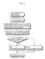
- Fig. 2 shows the procedure for abnormality recovery processing performed when the reset switch 2 is pressed.
- the reset switch 2 is based on the premise that it is pressed when the liquid crystal projector circuit 8 is in the power on mode in some cases and is pressed when the liquid crystal projector circuit 8 is in the standby mode in the other cases.
- a RAM (not shown) in the microcomputer 1 is first cleared (step 1).
- input-output ports, excluding a control port of the projecting lamp power supply circuit 3 and a control port of the fan power supply circuit 5, are initialized (step 2).
- the microcomputer 1 When the reset switch 2 is pressed in a case where the liquid crystal projector circuit 8 is in the power on mode, therefore, the microcomputer 1 can be initialized without turning the projecting lamp 4 off and stopping the fan 6. That is, the abnormal state of the microcomputer 1 can be recovered without turning the projecting lamp 4 off and stopping the fan 6. Further, the projector circuit power supply 7 is initialized to the off state, so that the power supply of the liquid crystal projector circuit 8 to the semiconductor is shut off. Accordingly, the abnormal state is solved.
- the last power mode information is read out of the EEPROM 10 (step 3).
- a power mode (a power on mode or a standby mode) before pressing the reset switch 2 is judged on the basis of the read last power mode information (step 4).
- the liquid crystal projector circuit 8 is returned to the power on mode (step 5). The abnormal recovery processing is terminated.
- the liquid crystal projector circuit 8 is returned to the standby mode (step 6). The abnormal recovery processing is terminated.
Landscapes
- Physics & Mathematics (AREA)
- General Physics & Mathematics (AREA)
- Engineering & Computer Science (AREA)
- Multimedia (AREA)
- Signal Processing (AREA)
- Chemical & Material Sciences (AREA)
- Crystallography & Structural Chemistry (AREA)
- Projection Apparatus (AREA)
- Liquid Crystal (AREA)
- Transforming Electric Information Into Light Information (AREA)
Abstract
Description
- The present invention relates to processing used for a liquid crystal projector.
- In recent years, in liquid crystal projectors, a projecting lamp for projecting an image written into a liquid crystal cell on a screen has been increased in luminance for improving its brightness performance. Further, there is a tendency to miniaturize the liquid crystal projector.
- On the other hand, an electric circuit in the liquid crystal projector is required to cope with high resolution and enhance its function by increasing the performance of a personal computer. A semiconductor device having a high integration degree tends to be used, and its power supply voltage is low.
- Used as the projecting lamp for projecting the image written into the liquid crystal cell on the screen are a metal halide projecting lamp and a very high pressure mercury projecting lamp. When the lamp is turned on, noises occur. The noises are not restrained as the luminance of the projecting lamp is increased. On the contrary, the noises are liable to be increased. Further, as the liquid crystal projector is miniaturized, the projecting lamp tends to approach the electric circuit.
- As the power supply voltage of the electric circuit using the semiconductor having a high integration degree, 3.3 volts have been in the main current. In this state, the noises at the time when the projecting lamp is turned on may affect the electric circuit, resulting in malfunction. When a microcomputer malfunctions, the malfunction may not, in some cases, be recovered unless the power supply is turned off once or the microcomputer is reset.
- In general setting, this state can be recovered by turning the power supply on after turning it off once or pressing a reset switch as in a recent personal computer. In the case of the liquid crystal projector, however, when the operation is performed, the projecting lamp is turned off once. The metal halide projecting lamp and the very high pressure mercury projecting lamp cannot be turned on again immediately after being turned off once. One to two minutes must be waited for until the temperature in the projecting lamp is reduced.
- The same is true for a case where the reset switch is provided to reset the microcomputer. The liquid crystal projector enters a standby state where the projecting lamp is turned off. When an attempt to operate the liquid crystal projector again is made, one or two minutes must be waited for.
- An object of the present invention is to provide a liquid crystal projector capable of immediately recovering, when an abnormality occurs in the liquid crystal projector, the abnormality and capable of solving trouble in waiting for one to two minutes until the temperature of a projecting lamp is reduced.
- In a liquid crystal projector using a microcomputer as a control unit of the liquid crystal projector and comprising a projecting lamp for projecting an image written into a liquid crystal cell and a cooling fan for the projecting lamp, a first liquid crystal projector according to the present invention is characterized by comprising a reset switch for resetting the operation of the microcomputer; and abnormality recovery means for initializing, when the liquid crystal projector is in a power on mode, other circuits and the microcomputer without stopping the projecting lamp and the cooling fan when the reset switch is turned on.
- In a liquid crystal projector using a microcomputer as a control unit of the liquid crystal projector and comprising a projecting lamp for projecting an image written into a liquid crystal cell and a cooling fan for the projecting lamp, a second liquid crystal projector according to the present invention is characterized by comprising a reset switch for resetting the operation of the microcomputer; and an abnormality recovery circuit for initializing, when the liquid crystal projector is in a power on mode, other circuits and the microcomputer without stopping the projecting lamp and the cooling fan when the reset switch is turned on.
- According to the present invention, even when an abnormality occurs in the liquid crystal projector, the abnormality can be recovered without tuning the projecting lamp off. Accordingly, the abnormal state can be quickly recovered without requiring a waiting time period for cooling the projecting lamp.
- The foregoing and other objects, features, aspects and advantages of the present invention will become more apparent from the following detailed description of the present invention when taken in conjunction with the accompanying drawings.
-
- Fig. 1 is a block diagram showing the configuration of a liquid crystal projector; and
- Fig. 2 is a flow chart showing the procedure for abnormality recovery processing.
-
- Referring now to the drawings, an embodiment of the present invention will be described.
- Fig. 1 illustrates the configuration of a liquid crystal projector.
- A
microcomputer 1 mainly controls a liquid crystal projector circuit (a signal processing circuit) 8. Further, themicrocomputer 1 is connected to a lamppower supply circuit 3, a fanpower supply circuit 5, and a projectorcircuit power supply 7 in order to carry out on-off control of a projectinglamp 4 for projecting an image written into a liquid crystal cell on a screen and power on/standby mode switching control of the liquidcrystal projector circuit 8. Further, themicrocomputer 1 comprises an EEPROM (Electrically Erasable and Programmable ROM) 10, which is a nonvolatile memory, in order to store the state of the liquid crystal projector. - A
reset switch 2 is connected to an NMI (Non-maskable Interrupt) terminal of themicrocomputer 1. A command from a user is entered into themicrocomputer 1 by a key (KEW SW) in a control unit and anoperation unit 9 composed of a remote control. - In such a configuration, when the power is inputted to the
microcomputer 1, themicrocomputer 1 sets the liquidcrystal projector circuit 8 in a standby mode. That is, all the projecting lamppower supply circuit 3, the fanpower supply circuit 5, and the projectorcircuit power supply 7 are set in an off state. - Thereafter, when a power on operation is performed by the
operation unit 9, themicrocomputer 1 sets the liquidcrystal projector circuit 8 in a power on mode. That is, all the projecting lamppower supply circuit 3, the fanpower supply circuit 5, and the projectorcircuit power supply 7 are set in an on state. When the power on operation is performed, information indicating that the liquidcrystal projector circuit 8 is in the power on mode is stored in the EEPROM 10 as last power mode information. - On the other hand, when a power off operation is performed by the
operation unit 9, themicrocomputer 1 sets the liquidcrystal projector circuit 8 in a standby mode. That is, all the projecting lamppower supply circuit 3, the fanpower supply circuit 5, and the projectorcircuit power supply 7 are set in the off state. When the power off operation is performed, information indicating that the liquidcrystal projector circuit 8 is in the standby mode is stored in the EEPROM 10 as last power mode information. - When any abnormal state occurs in a case where the liquid
crystal projector circuit 8 is in the power on mode, the user presses thereset switch 2. When thereset switch 2 is pressed, a program for themicrocomputer 1 is forced to be jumped to an NMI address, to execute an abnormality recovery processing program at the address. - Fig. 2 shows the procedure for abnormality recovery processing performed when the
reset switch 2 is pressed. - The
reset switch 2 is based on the premise that it is pressed when the liquidcrystal projector circuit 8 is in the power on mode in some cases and is pressed when the liquidcrystal projector circuit 8 is in the standby mode in the other cases. - In the abnormality recovery processing, a RAM (not shown) in the
microcomputer 1 is first cleared (step 1). In this case, input-output ports, excluding a control port of the projecting lamppower supply circuit 3 and a control port of the fanpower supply circuit 5, are initialized (step 2). - When the
reset switch 2 is pressed in a case where the liquidcrystal projector circuit 8 is in the power on mode, therefore, themicrocomputer 1 can be initialized without turning the projectinglamp 4 off and stopping thefan 6. That is, the abnormal state of themicrocomputer 1 can be recovered without turning the projectinglamp 4 off and stopping thefan 6. Further, the projectorcircuit power supply 7 is initialized to the off state, so that the power supply of the liquidcrystal projector circuit 8 to the semiconductor is shut off. Accordingly, the abnormal state is solved. - When the
reset switch 2 is pressed in a case where the liquidcrystal projector circuit 8 is in the standby mode, it goes without saying that the projectinglamp 4 and thefan 6 are maintained in an off state. - Thereafter, the last power mode information is read out of the EEPROM 10 (step 3). A power mode (a power on mode or a standby mode) before pressing the
reset switch 2 is judged on the basis of the read last power mode information (step 4). - When it is judged that the power mode before pressing the
reset switch 2 is the power on mode, the liquidcrystal projector circuit 8 is returned to the power on mode (step 5). The abnormal recovery processing is terminated. - When it is judged that the power mode before pressing the
reset switch 2 is the standby mode, the liquidcrystal projector circuit 8 is returned to the standby mode (step 6). The abnormal recovery processing is terminated. - Although the present invention has been described and illustrated in detail, it is clearly understood that the same is by way of illustration and example only and is not to be taken by way of limitation, the spirit and scope of the present invention being limited only by the terms of the appended claims.
Claims (2)
- In a liquid crystal projector using a microcomputer as a control unit of the liquid crystal projector and comprising a projecting lamp for projecting an image written into a liquid crystal cell and a cooling fan for the projecting lamp, the liquid crystal projector comprising:a reset switch for resetting the operation of the microcomputer; andabnormality recovery means for initializing, when the liquid crystal projector is in a power on mode, other circuits and the microcomputer without stopping the projecting lamp and the cooling fan when the reset switch is turned on.
- In a liquid crystal projector using a microcomputer as a control unit of the liquid crystal projector and comprising a projecting lamp for projecting an image written into a liquid crystal cell and a cooling fan for the projecting lamp, the liquid crystal projector comprising:a reset switch for resetting the operation of the microcomputer; andan abnormality recovery circuit for initializing, when the liquid crystal projector is in a power on mode, other circuits and the microcomputer without stopping the projecting lamp and the cooling fan when the reset switch is turned on.
Applications Claiming Priority (2)
| Application Number | Priority Date | Filing Date | Title |
|---|---|---|---|
| JP2000124601A JP3322664B2 (en) | 2000-04-25 | 2000-04-25 | LCD projector |
| JP2000124601 | 2000-04-25 |
Publications (2)
| Publication Number | Publication Date |
|---|---|
| EP1150502A1 true EP1150502A1 (en) | 2001-10-31 |
| EP1150502B1 EP1150502B1 (en) | 2008-12-17 |
Family
ID=18634707
Family Applications (1)
| Application Number | Title | Priority Date | Filing Date |
|---|---|---|---|
| EP01109871A Expired - Lifetime EP1150502B1 (en) | 2000-04-25 | 2001-04-23 | Liquid crystal projector |
Country Status (5)
| Country | Link |
|---|---|
| US (1) | US6476560B2 (en) |
| EP (1) | EP1150502B1 (en) |
| JP (1) | JP3322664B2 (en) |
| KR (1) | KR100773185B1 (en) |
| DE (1) | DE60136991D1 (en) |
Families Citing this family (9)
| Publication number | Priority date | Publication date | Assignee | Title |
|---|---|---|---|---|
| JP3322664B2 (en) * | 2000-04-25 | 2002-09-09 | 三洋電機株式会社 | LCD projector |
| CN100367107C (en) * | 2003-04-11 | 2008-02-06 | 台达电子工业股份有限公司 | Heat sink for projection display and its operation method |
| TWI333120B (en) * | 2003-06-02 | 2010-11-11 | Seiko Epson Corp | Projection device having blower and/or lamp with feedback control |
| US7546025B2 (en) * | 2004-07-06 | 2009-06-09 | Hewlett-Packard Development Company, L.P. | Media projector system |
| US7286347B2 (en) * | 2004-08-10 | 2007-10-23 | Dupont Displays | Electronic device having a temperature control system |
| US7233493B2 (en) | 2004-08-10 | 2007-06-19 | E. I. Du Pont De Nemours And Company | Electronic device having a temperature control system including a ductwork assembly |
| JP4619310B2 (en) * | 2005-06-23 | 2011-01-26 | 三洋電機株式会社 | Projection-type image display device |
| US7559657B2 (en) * | 2006-01-30 | 2009-07-14 | Infocus Corporation | Projection device |
| US11351766B2 (en) | 2019-11-11 | 2022-06-07 | Textile Rubber And Chemical Company, Inc. | Process for applying film backing to synthetic turf and product |
Citations (3)
| Publication number | Priority date | Publication date | Assignee | Title |
|---|---|---|---|---|
| DE19511810A1 (en) * | 1994-03-30 | 1995-10-26 | Lg Electronics Inc | Projection type LCD projector lamp drive unit |
| US5491525A (en) * | 1992-11-24 | 1996-02-13 | Hitachi, Ltd. | Illumination unit for liquid crystal projection display apparatus and liquid crystal display apparatus having it used |
| US5567030A (en) * | 1993-03-30 | 1996-10-22 | Goldstar Co., Ltd. | Method for controlling picture size in an LCD projector |
Family Cites Families (11)
| Publication number | Priority date | Publication date | Assignee | Title |
|---|---|---|---|---|
| JPH01116535A (en) | 1987-10-29 | 1989-05-09 | Canon Inc | Cooling device for projector |
| JP3052318B2 (en) * | 1989-10-31 | 2000-06-12 | セイコーエプソン株式会社 | Projector and control method thereof |
| JP2903655B2 (en) | 1990-06-21 | 1999-06-07 | セイコーエプソン株式会社 | Projection display device |
| JPH06130492A (en) | 1992-10-16 | 1994-05-13 | Tohoku Ricoh Co Ltd | Overhead projector |
| JP3424023B2 (en) | 1994-08-30 | 2003-07-07 | カシオ計算機株式会社 | LCD projector |
| US6011607A (en) * | 1995-02-15 | 2000-01-04 | Semiconductor Energy Laboratory Co., | Active matrix display with sealing material |
| JPH08234848A (en) | 1995-02-28 | 1996-09-13 | Sony Corp | Cooling fan motor control device and projection device including the device |
| JPH10197952A (en) | 1997-01-10 | 1998-07-31 | Musashi Seimitsu Ind Co Ltd | Overhead projector |
| JPH11133505A (en) | 1997-10-30 | 1999-05-21 | Nikon Corp | projector |
| JP3646533B2 (en) | 1998-09-17 | 2005-05-11 | 株式会社日立製作所 | LCD projector |
| JP3322664B2 (en) * | 2000-04-25 | 2002-09-09 | 三洋電機株式会社 | LCD projector |
-
2000
- 2000-04-25 JP JP2000124601A patent/JP3322664B2/en not_active Expired - Fee Related
-
2001
- 2001-04-23 DE DE60136991T patent/DE60136991D1/en not_active Expired - Lifetime
- 2001-04-23 US US09/839,356 patent/US6476560B2/en not_active Expired - Fee Related
- 2001-04-23 EP EP01109871A patent/EP1150502B1/en not_active Expired - Lifetime
- 2001-04-24 KR KR1020010021937A patent/KR100773185B1/en not_active Expired - Fee Related
Patent Citations (3)
| Publication number | Priority date | Publication date | Assignee | Title |
|---|---|---|---|---|
| US5491525A (en) * | 1992-11-24 | 1996-02-13 | Hitachi, Ltd. | Illumination unit for liquid crystal projection display apparatus and liquid crystal display apparatus having it used |
| US5567030A (en) * | 1993-03-30 | 1996-10-22 | Goldstar Co., Ltd. | Method for controlling picture size in an LCD projector |
| DE19511810A1 (en) * | 1994-03-30 | 1995-10-26 | Lg Electronics Inc | Projection type LCD projector lamp drive unit |
Also Published As
| Publication number | Publication date |
|---|---|
| JP2001305659A (en) | 2001-11-02 |
| KR100773185B1 (en) | 2007-11-02 |
| US6476560B2 (en) | 2002-11-05 |
| KR20010098820A (en) | 2001-11-08 |
| JP3322664B2 (en) | 2002-09-09 |
| DE60136991D1 (en) | 2009-01-29 |
| EP1150502B1 (en) | 2008-12-17 |
| US20010033279A1 (en) | 2001-10-25 |
Similar Documents
| Publication | Publication Date | Title |
|---|---|---|
| US6476560B2 (en) | Liquid crystal projector | |
| JPH11259189A (en) | Power supply control device for peripheral equipment | |
| KR100356097B1 (en) | Automatic turn off / on device for error correction | |
| US20030094924A1 (en) | Card type device serving as supplementary battery and host using the same | |
| WO2022048331A1 (en) | Method and device for card reidentification when sim card is disconnected, computer device, and medium | |
| EP2079230A2 (en) | Method for operating TV tuner card | |
| US20070106915A1 (en) | Reset circuit for automatically resetting an MCU upon turning on a power and the method thereof | |
| CN117153126B (en) | Drive circuit, display module and display device | |
| US7193624B2 (en) | Display apparatus with power saving capability | |
| US20070165040A1 (en) | Display apparatus capable of preventing firmware update failure and method thereof | |
| JPH0453943A (en) | Projection type display device | |
| JP2007201844A (en) | Power supply of electric equipment with tuner and power supply of electric equipment | |
| JP2000105639A (en) | Power saving circuit | |
| US20040085116A1 (en) | Circuit for combining on/off key and warm boot key to obtain a function of cold boot key in a portable information device | |
| US7133650B2 (en) | Power supply having stable reset function in mobile electronic unit | |
| JP3250608B2 (en) | Protection circuit for electrical equipment | |
| KR100358695B1 (en) | Controlling Method of Driving Display Device and Controlling Apparatus Thereof | |
| JPH11215717A (en) | Power supply | |
| KR0138558Y1 (en) | Power supplying circuit for electronic viewfinder | |
| CN100377068C (en) | serial memory program controller | |
| KR20040075540A (en) | A lamp driver having improved stability | |
| JPH07200116A (en) | Power connection circuit | |
| JP2001100691A (en) | Video display device | |
| CN116541078A (en) | State control system and method | |
| JP6641555B2 (en) | System start-up circuit, electric equipment and television device |
Legal Events
| Date | Code | Title | Description |
|---|---|---|---|
| PUAI | Public reference made under article 153(3) epc to a published international application that has entered the european phase |
Free format text: ORIGINAL CODE: 0009012 |
|
| AK | Designated contracting states |
Kind code of ref document: A1 Designated state(s): AT BE CH CY DE DK ES FI FR GB GR IE IT LI LU MC NL PT SE TR Kind code of ref document: A1 Designated state(s): DE FR GB |
|
| AX | Request for extension of the european patent |
Free format text: AL;LT;LV;MK;RO;SI |
|
| 17P | Request for examination filed |
Effective date: 20020328 |
|
| AKX | Designation fees paid |
Free format text: DE FR GB |
|
| GRAP | Despatch of communication of intention to grant a patent |
Free format text: ORIGINAL CODE: EPIDOSNIGR1 |
|
| GRAS | Grant fee paid |
Free format text: ORIGINAL CODE: EPIDOSNIGR3 |
|
| GRAS | Grant fee paid |
Free format text: ORIGINAL CODE: EPIDOSNIGR3 |
|
| GRAA | (expected) grant |
Free format text: ORIGINAL CODE: 0009210 |
|
| AK | Designated contracting states |
Kind code of ref document: B1 Designated state(s): DE FR GB |
|
| REG | Reference to a national code |
Ref country code: GB Ref legal event code: FG4D |
|
| REF | Corresponds to: |
Ref document number: 60136991 Country of ref document: DE Date of ref document: 20090129 Kind code of ref document: P |
|
| PLBE | No opposition filed within time limit |
Free format text: ORIGINAL CODE: 0009261 |
|
| STAA | Information on the status of an ep patent application or granted ep patent |
Free format text: STATUS: NO OPPOSITION FILED WITHIN TIME LIMIT |
|
| 26N | No opposition filed |
Effective date: 20090918 |
|
| REG | Reference to a national code |
Ref country code: GB Ref legal event code: 746 Effective date: 20130617 |
|
| PGFP | Annual fee paid to national office [announced via postgrant information from national office to epo] |
Ref country code: GB Payment date: 20130417 Year of fee payment: 13 Ref country code: DE Payment date: 20130508 Year of fee payment: 13 |
|
| PGFP | Annual fee paid to national office [announced via postgrant information from national office to epo] |
Ref country code: FR Payment date: 20130625 Year of fee payment: 13 |
|
| REG | Reference to a national code |
Ref country code: DE Ref legal event code: R084 Ref document number: 60136991 Country of ref document: DE Effective date: 20130612 |
|
| REG | Reference to a national code |
Ref country code: DE Ref legal event code: R119 Ref document number: 60136991 Country of ref document: DE |
|
| GBPC | Gb: european patent ceased through non-payment of renewal fee |
Effective date: 20140423 |
|
| REG | Reference to a national code |
Ref country code: FR Ref legal event code: ST Effective date: 20141231 |
|
| PG25 | Lapsed in a contracting state [announced via postgrant information from national office to epo] |
Ref country code: DE Free format text: LAPSE BECAUSE OF NON-PAYMENT OF DUE FEES Effective date: 20141101 Ref country code: GB Free format text: LAPSE BECAUSE OF NON-PAYMENT OF DUE FEES Effective date: 20140423 |
|
| REG | Reference to a national code |
Ref country code: DE Ref legal event code: R119 Ref document number: 60136991 Country of ref document: DE Effective date: 20141101 |
|
| PG25 | Lapsed in a contracting state [announced via postgrant information from national office to epo] |
Ref country code: FR Free format text: LAPSE BECAUSE OF NON-PAYMENT OF DUE FEES Effective date: 20140430 |