EP1150278A1 - Cleaning disc, magneto-optical disc apparatus and recording/reproducing apparatus - Google Patents
Cleaning disc, magneto-optical disc apparatus and recording/reproducing apparatus Download PDFInfo
- Publication number
- EP1150278A1 EP1150278A1 EP00976381A EP00976381A EP1150278A1 EP 1150278 A1 EP1150278 A1 EP 1150278A1 EP 00976381 A EP00976381 A EP 00976381A EP 00976381 A EP00976381 A EP 00976381A EP 1150278 A1 EP1150278 A1 EP 1150278A1
- Authority
- EP
- European Patent Office
- Prior art keywords
- disk
- cleaning
- magnetic head
- magneto
- optical
- Prior art date
- Legal status (The legal status is an assumption and is not a legal conclusion. Google has not performed a legal analysis and makes no representation as to the accuracy of the status listed.)
- Withdrawn
Links
Images







Classifications
-
- G—PHYSICS
- G11—INFORMATION STORAGE
- G11B—INFORMATION STORAGE BASED ON RELATIVE MOVEMENT BETWEEN RECORD CARRIER AND TRANSDUCER
- G11B7/00—Recording or reproducing by optical means, e.g. recording using a thermal beam of optical radiation by modifying optical properties or the physical structure, reproducing using an optical beam at lower power by sensing optical properties; Record carriers therefor
- G11B7/12—Heads, e.g. forming of the optical beam spot or modulation of the optical beam
- G11B7/121—Protecting the head, e.g. against dust or impact with the record carrier
-
- G—PHYSICS
- G11—INFORMATION STORAGE
- G11B—INFORMATION STORAGE BASED ON RELATIVE MOVEMENT BETWEEN RECORD CARRIER AND TRANSDUCER
- G11B11/00—Recording on or reproducing from the same record carrier wherein for these two operations the methods are covered by different main groups of groups G11B3/00 - G11B7/00 or by different subgroups of group G11B9/00; Record carriers therefor
- G11B11/10—Recording on or reproducing from the same record carrier wherein for these two operations the methods are covered by different main groups of groups G11B3/00 - G11B7/00 or by different subgroups of group G11B9/00; Record carriers therefor using recording by magnetic means or other means for magnetisation or demagnetisation of a record carrier, e.g. light induced spin magnetisation; Demagnetisation by thermal or stress means in the presence or not of an orienting magnetic field
- G11B11/105—Recording on or reproducing from the same record carrier wherein for these two operations the methods are covered by different main groups of groups G11B3/00 - G11B7/00 or by different subgroups of group G11B9/00; Record carriers therefor using recording by magnetic means or other means for magnetisation or demagnetisation of a record carrier, e.g. light induced spin magnetisation; Demagnetisation by thermal or stress means in the presence or not of an orienting magnetic field using a beam of light or a magnetic field for recording by change of magnetisation and a beam of light for reproducing, i.e. magneto-optical, e.g. light-induced thermomagnetic recording, spin magnetisation recording, Kerr or Faraday effect reproducing
- G11B11/10582—Record carriers characterised by the selection of the material or by the structure or form
- G11B11/10584—Record carriers characterised by the selection of the material or by the structure or form characterised by the form, e.g. comprising mechanical protection elements
-
- G—PHYSICS
- G11—INFORMATION STORAGE
- G11B—INFORMATION STORAGE BASED ON RELATIVE MOVEMENT BETWEEN RECORD CARRIER AND TRANSDUCER
- G11B11/00—Recording on or reproducing from the same record carrier wherein for these two operations the methods are covered by different main groups of groups G11B3/00 - G11B7/00 or by different subgroups of group G11B9/00; Record carriers therefor
- G11B11/10—Recording on or reproducing from the same record carrier wherein for these two operations the methods are covered by different main groups of groups G11B3/00 - G11B7/00 or by different subgroups of group G11B9/00; Record carriers therefor using recording by magnetic means or other means for magnetisation or demagnetisation of a record carrier, e.g. light induced spin magnetisation; Demagnetisation by thermal or stress means in the presence or not of an orienting magnetic field
- G11B11/105—Recording on or reproducing from the same record carrier wherein for these two operations the methods are covered by different main groups of groups G11B3/00 - G11B7/00 or by different subgroups of group G11B9/00; Record carriers therefor using recording by magnetic means or other means for magnetisation or demagnetisation of a record carrier, e.g. light induced spin magnetisation; Demagnetisation by thermal or stress means in the presence or not of an orienting magnetic field using a beam of light or a magnetic field for recording by change of magnetisation and a beam of light for reproducing, i.e. magneto-optical, e.g. light-induced thermomagnetic recording, spin magnetisation recording, Kerr or Faraday effect reproducing
- G11B11/10595—Control of operating function
-
- G—PHYSICS
- G11—INFORMATION STORAGE
- G11B—INFORMATION STORAGE BASED ON RELATIVE MOVEMENT BETWEEN RECORD CARRIER AND TRANSDUCER
- G11B19/00—Driving, starting, stopping record carriers not specifically of filamentary or web form, or of supports therefor; Control thereof; Control of operating function ; Driving both disc and head
- G11B19/02—Control of operating function, e.g. switching from recording to reproducing
- G11B19/12—Control of operating function, e.g. switching from recording to reproducing by sensing distinguishing features of or on records, e.g. diameter end mark
-
- G—PHYSICS
- G11—INFORMATION STORAGE
- G11B—INFORMATION STORAGE BASED ON RELATIVE MOVEMENT BETWEEN RECORD CARRIER AND TRANSDUCER
- G11B19/00—Driving, starting, stopping record carriers not specifically of filamentary or web form, or of supports therefor; Control thereof; Control of operating function ; Driving both disc and head
- G11B19/20—Driving; Starting; Stopping; Control thereof
- G11B19/26—Speed-changing arrangements; Reversing arrangements; Drive-transfer means therefor
-
- G—PHYSICS
- G11—INFORMATION STORAGE
- G11B—INFORMATION STORAGE BASED ON RELATIVE MOVEMENT BETWEEN RECORD CARRIER AND TRANSDUCER
- G11B5/00—Recording by magnetisation or demagnetisation of a record carrier; Reproducing by magnetic means; Record carriers therefor
- G11B5/41—Cleaning of heads
-
- G—PHYSICS
- G11—INFORMATION STORAGE
- G11B—INFORMATION STORAGE BASED ON RELATIVE MOVEMENT BETWEEN RECORD CARRIER AND TRANSDUCER
- G11B11/00—Recording on or reproducing from the same record carrier wherein for these two operations the methods are covered by different main groups of groups G11B3/00 - G11B7/00 or by different subgroups of group G11B9/00; Record carriers therefor
- G11B11/10—Recording on or reproducing from the same record carrier wherein for these two operations the methods are covered by different main groups of groups G11B3/00 - G11B7/00 or by different subgroups of group G11B9/00; Record carriers therefor using recording by magnetic means or other means for magnetisation or demagnetisation of a record carrier, e.g. light induced spin magnetisation; Demagnetisation by thermal or stress means in the presence or not of an orienting magnetic field
- G11B11/105—Recording on or reproducing from the same record carrier wherein for these two operations the methods are covered by different main groups of groups G11B3/00 - G11B7/00 or by different subgroups of group G11B9/00; Record carriers therefor using recording by magnetic means or other means for magnetisation or demagnetisation of a record carrier, e.g. light induced spin magnetisation; Demagnetisation by thermal or stress means in the presence or not of an orienting magnetic field using a beam of light or a magnetic field for recording by change of magnetisation and a beam of light for reproducing, i.e. magneto-optical, e.g. light-induced thermomagnetic recording, spin magnetisation recording, Kerr or Faraday effect reproducing
- G11B11/10532—Heads
Definitions
- the present invention relates to a cleaning disk and a magneto-optical disk drive apparatus for removing dirt, dust and other foreign particles stuck to the magnetic head and optical head of an information recording/reproduction apparatus.
- the present invention relates to a recording/reproduction apparatus, such as a floppy disk drive (hereafter simply referred to as an FDD), a minidisk apparatus (hereafter simply referred to as an MD apparatus) and a magneto-optical data file apparatus, provided with a sliding contact type magnetic head to apply a modulated magnetic field to a recording medium. More particularly, the present invention relates to a recording/reproduction apparatus capable of carrying out recording and reproduction on both types of disk media, that is, a magnetic head cleaning disk having a cleaning layer on its face making sliding contact with the magnetic head and an ordinary recording/reproduction disk.
- a recording/reproduction apparatus capable of carrying out recording and reproduction on both types of disk media, that is, a magnetic head cleaning disk having a cleaning layer on its face making sliding contact with the magnetic head and an ordinary recording/reproduction disk.
- Optical disk drive apparatuses are available as an optical disk drive apparatus based on a thermal change system wherein the crystals of the recording layer of an optical disk are changed in phases by the heat of the laser light of an optical head to carry out recording, typified by a CD-R and a DVD, and a magneto-optical disk drive apparatus based on a magneto-optical system wherein the heat by the laser light of an optical head is combined with the modulated magnetic field by a magnetic head to carry out recording, typified by an MD.
- an optical head for emitting a light beam applied to a magneto-optical recording layer is disposed on one side of a magneto-optical disk rotated by a disk rotation mechanism (spindle motor), and a magnetic head for applying an external magnetic field to the magneto-optical recording layer is disposed on the other side so as to be disposed opposite to the optical head.
- the magneto-optical disk drive apparatus applies a modulated magnetic field, the direction of which is modulated depending on an information signal to be recorded from the magnetic head, to the magneto-optical recording layer of the magneto-optical disk to be rotated, and gathers the light beam emitted from the optical head and applies the light beam.
- a portion heated to Curie temperature or more by this application of the light beam so as to be demagnetized is magnetized depending on the direction of the magnetic field applied from the magnetic head, the portion is cooled to Curie temperature or less by the relative movement of the light beam owing to the rotation of the magneto-optical disk, and the direction of the magnetization is fixed, whereby the information signal is recorded.
- the dust and the like when dust and the like are stuck to the surfaces of the objective lens of the optical head and the magnetic head relating to the recording and reproduction of signals, the dust and the like may prevent the laser light from reaching the magneto-optical recording layer of the magneto-optical disk, and may be stuck to the surface of the disk, thereby increasing wear of the magneto-optical disk and making scratches, furthermore, disturbing the spacing between the magnetic head and the magneto-optical disk and increasing errors owing to the disturbance.
- a cleaning disk is used conventionally to remove stain owing to dust and the like on the surfaces of the objective lens and the magnetic head.
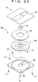
- An example of the disk is disclosed in Japanese Laid-open Patent Application Hei 7-6430. This disk is shown in FIG. 20.
- FIG. 20 is an exploded perspective view showing the conventional cleaning disk.
- a conventional disk 100 is used for an MD apparatus, and just as in the case of a general writable minidisk, lens-cleaning members 27 having the shape of a raised brush fur bundle are disposed on the surface of a magneto-optical disk 104 provided with a clamping hub 19 at its center, and a head-cleaning member 22 having a nearly sheet-like shape and capable of being made contact with the end of the magnetic head at the recording position is bonded in a predetermined radial range on the surface of the disk disposed opposite to the magnetic head,.
- the cleaning disk 100 is rotatably housed in the cartridge 6 comprising an upper cartridge 26 and a lower cartridge 28.
- the upper cartridge 26 is secured to the lower cartridge 28 with screws 9.
- a disk detection groove 29 is formed in a part of the cartridge 6, whereby the magneto-optical disk drive apparatus can detect that the cleaning disk 100 is a recordable disk, just like the magneto-optical disk for ordinary recording.
- This cartridge 6 has a configuration common to the cartridge of the magneto-optical disk for ordinary recording.
- the magneto-optical disk drive apparatus determines that the disk is a recording disk by using a disk detection switch and carries out recording operation.
- the lens-cleaning members 27 make contact with the objective lens of the optical head, and the head-cleaning member on the opposite side makes contact with the magnetic head, thereby cleaning the objective lens and the magnetic head in accordance with the rotation of the magneto-optical disk 104.
- stop operation is carried out, and the cleaning disk is taken out of the magneto-optical disk drive apparatus, thereby completing cleaning.
- the head-cleaning member may be worn out, and dust and the like removed from the sliding face of the magnetic head by the head-cleaning member may be stuck again to the sliding face at the end of the magnetic head.
- a lubrication film of about 10 ⁇ m to 20 ⁇ m is formed on the magneto-optical recording layer.
- the spacing between the magnetic core of the magnetic head and the above-mentioned magneto-optical recording layer is about 0.01 mm to 0.1 mm.
- the magnetic head cleaning disk a head-cleaning member of 0.2 mm to 0.4 mm in thickness is present on the magneto-optical recording film.
- the spacing between the magnetic core and the magneto-optical recording film is two times or more that of the ordinary magneto-optical disk.
- a modulated current to be supplied to the magnetic head is set larger so that recording on the cleaning disk can be carried out without problems, whereby the magnetic head is driven by the same current value as that used during recording on the cleaning disk, even during recording on the ordinary recording magneto-optical disk.
- the rotation speed of the disk tends to increase as the speed of information transfer increases; in the above-mentioned conventional recording/reproduction apparatus, when the cleaning disk is used, the sliding face of the magnetic head may wear out and the objective lens actuator of the optical head may break because of high rotation speed, resulting in problems. To solve the above-mentioned problems, the necessity for identifying cleaning disk is intensified.
- a type indication portion for identifying the type of disk is provided by forming a notch in a part of the cartridge as disclosed in Japanese Laid-open Patent Application Hei 5-135541, for example.
- a special-purpose detection switch is required for the magneto-optical disk drive apparatus; this increases the number of components for the magneto-optical disk drive apparatus and makes the structure more complicated; furthermore, when it is necessary to increase the modulated current value of the magnetic head required for recording because the specifications of the cleaning disk, such as the thickness of the head-cleaning member, are changed, no countermeasure can be taken, result in a problem.
- a recording/reproduction apparatus As a recording/reproduction apparatus provided with a magnetic head, a recording/reproduction apparatus based on a magnetic recording/reproduction system, typified by an FDD, wherein information is recorded/reproduced on a disk medium by the magnetic head, is available.
- a recording/reproduction apparatus based on a magneto-optical recording/reproduction system, typified by an MD, wherein information is recorded/reproduced on a disk medium by the combination of the magnetic head and the optical head is also available.
- an optical head for emitting a light beam applied to a magneto-optical recording layer is disposed on one side of a magneto-optical disk rotated by a disk rotation mechanism (spindle motor), and a magnetic head for applying an external magnetic field to the magneto-optical recording layer is disposed on the other side so as to be disposed opposite to the optical head.
- the recording/reproduction apparatus applies a modulated magnetic field, the direction of which is modulated depending on an information signal to be recorded from the magnetic head, to the magneto-optical recording layer of the rotated magneto-optical disk, and gathers the light beam emitted from the optical head and applies the light beam.
- the portion heated to Curie temperature or more by this application of the light beam so as to be demagnetized is magnetized depending on the direction of the magnetic field applied from the magnetic head, the portion is cooled to Curie temperature or less by the relative movement of the light beam owing to the rotation of the magneto-optical disk, and the direction of the magnetization is fixed, whereby the information signal is recorded.
- a recording/reproduction apparatus provided with a sliding contact type magnetic head for recording information signals with the head body of the magnetic head making contact with the disk is used for an MD for example.
- dust and the like deposited on the magneto-optical disk may be stuck to the head sliding face of the magnetic head making sliding contact with the magneto-optical disk during recording operation; owing to the use for a long time, dust is deposited on the head sliding face.
- stain owing to dust and the like on the sliding face of the magnetic head may increase wear of the magnetic head and the magneto-optical disk and make scratches, furthermore, disturb the spacing between the magnetic head and the magneto-optical disk and increase errors owing to the disturbance.
- the cleaning layer may wear out, and dust and the like removed from the sliding face of the magnetic head by the cleaning layer may be stuck again to the sliding face of the magnetic head.
- the cleaning disk is used in the case of an MD apparatus for example, it is supposed that the ordinary recording operation is carried out during cleaning, and that the portion used for recording, i.e., the portion used for cleaning, is recorded as a first piece of music after the cleaning. Therefore, when the cleaning disk is used next, the cleaning of the magnetic head starts at the position of a second piece of music; this configuration prevents the magnetic head from sliding at the same portion of the above-mentioned cleaning layer.
- a lubrication film of about 10 ⁇ m to 20 ⁇ m is formed on the magneto-optical recording layer.
- the spacing between the magnetic core of the magnetic head and the above-mentioned magneto-optical recording film is about 0.01 mm to 0.1 mm.
- the cleaning disk a head cleaning layer of 0.2 mm to 0.4 mm in thickness is present on the magneto-optical recording film.
- the spacing between the magnetic core and the magneto-optical recording film is two times or more that of the ordinary magneto-optical disk.
- a modulated current to be supplied to the magnetic head is set larger so that recording on the cleaning disk can be carried out without problems, whereby the magnetic head is driven by the same current value as that used during recording on the cleaning disk, even during recording on the ordinary magneto-optical disk.
- the rotation speed of the disk tends to increase as the speed of information transfer increases; in the above-mentioned conventional recording/reproduction apparatus, when the cleaning disk is used, the sliding face of the magnetic head may wear out because of high rotation speed, resulting in problems.
- An object of the present invention is to provide a cleaning disk and a magneto-optical disk drive apparatus being simple in structure, adaptable to cleaning disks having various specifications, low in power consumption, low in electromagnetic noise, and preventing damage to the magnetic head and the optical head.
- Another object of the present invention is to provide a recording/reproduction apparatus being low in power consumption and low in electromagnetic noise.
- Still another object of the present invention is to provide a recording/reproduction apparatus capable of reducing wear on the sliding face of the magnetic head.
- the cleaning disk in accordance with the present invention comprises a magneto-optical disk having an information layer, and a head-cleaning member, provided on the magneto-optical disk, for cleaning the magnetic head of a magneto-optical disk drive apparatus, wherein information regarding a magnetic head cleaning condition for setting the operation condition of the magneto-optical disk drive apparatus during cleaning of the magnetic head has been recorded in advance on the information layer of the magneto-optical disk.
- the above-mentioned cleaning condition is for example a recording condition during cleaning of the magnetic head, more specifically, the magnetic head drive current (modulated current) during cleaning, the rotation speed of the magneto-optical disk during cleaning or the laser powel of the optical head during cleaning. Furthermore, the above-mentioned cleaning condition has been recorded in the index area on the information layer of the magneto-optical disk for example.
- information regarding the magnetic head cleaning condition in the case when the cleaning disk is used for example, an appropriate value of the drive current (modulated current) of the magnetic head during cleaning, an appropriate value of the rotation speed of the magneto-optical disk during cleaning or an appropriate value of the laser power of the optical head during cleaning can be read by the optical head from the cleaning disk.
- the operation condition of the magneto-optical disk drive apparatus during cleaning can be set at an appropriate state depending on the cleaning disk.
- the information regarding the cleaning condition can be read without providing any special structure, whereby the structure of the magneto-optical disk drive apparatus does not become complicated.
- the information regarding the cleaning condition is read by the optical head, it is possible to discriminate between the cleaning disk and the ordinary magneto-optical disk without requiring any special configuration, whereby the structure of the magneto-optical disk drive apparatus does not become complicated for disk discrimination. Furthermore, even when the specifications of the cleaning disk are modified, a countermeasure can be taken by changing the cleaning condition to be recorded on the cleaning disk in accordance therewith; even in the magneto-optical disk drive apparatus, by setting the operation condition depending on the cleaning condition, the operation condition of the magneto-optical disk drive apparatus during cleaning can be set at an appropriate state depending on the cleaning disk at all times.
- a magneto-optical disk drive apparatus in accordance with the present invention has a magnetic head and an optical head, wherein information regarding the cleaning condition is read from a cleaning disk comprising a magneto-optical disk and a magnetic head-cleaning member provided thereon, on the information layer of which the information regarding the magnetic head cleaning condition is recorded, and an operation condition (regarding/reproduction condition) during cleaning is controlled on the basis of the cleaning condition.
- information regarding the magnetic head cleaning condition in the case when the cleaning disk is used for example, an appropriate value of the drive current (modulated current) of the magnetic head during cleaning, an appropriate value of the rotation speed of the magneto-optical disk during cleaning or an appropriate value of the laser power of the optical head during cleaning can be read by the optical head from the cleaning disk.
- the operation condition of the magneto-optical disk drive apparatus during cleaning can be set at an appropriate state depending on the cleaning disk.
- the information regarding the cleaning condition can be read without providing any special structure, whereby the structure of the magneto-optical disk drive apparatus does not become complicated.
- the operation condition of the magneto-optical disk drive apparatus during cleaning can be set at an appropriate state depending on the cleaning disk at all times.
- a first example of the above-mentioned cleaning condition is the drive current of the magnetic head during cleaning
- an example of the operation condition is the drive current of the magnetic head corresponding to the cleaning condition; the drive current of the magnetic head during cleaning is made larger than that during ordinary recording.
- the drive current (modulated current) to be supplied to the magnetic head is made smaller than that during recording on the cleaning disk, whereby the power consumption and electromagnetic noise of the magneto-optical disk drive apparatus can be reduced.
- a second example of the above-mentioned cleaning condition is the rotation speed of the magneto-optical disk during cleaning
- an example of the operation condition is the rotation speed of the magneto-optical disk corresponding to the cleaning condition; the rotation speed of the magneto-optical disk during cleaning is made lower than that during ordinary recording or reproduction.
- a third example of the above-mentioned cleaning condition is the laser power of the optical head during cleaning, and an example of the operation condition is the laser power of the optical head corresponding to the cleaning condition; the laser power of the optical head during cleaning is made lower than that during ordinary recording.
- the laser power of the optical head may be used as the laser power for reproduction during cleaning, and cleaning may be carried out while the magnetic head is made sliding contact with the cleaning disk, and then information designating the area of the cleaning disk used during the cleaning may be recorded in the index area on the information layer of the cleaning disk.
- the power consumption of the magneto-optical disk drive apparatus during cleaning can be reduced, and the usable remaining area and the number of usage times of the cleaning disk can be grasped from the information in the index area.
- disk formatting may be disabled during cleaning.
- At least the rewriting or erasing of the information in the index area may be disabled during cleaning.
- a first recording/reproduction apparatus in accordance with the present invention comprising a magnetic head and capable of using a magnetic head cleaning disk having a cleaning layer on a face making sliding contact with the magnetic head as well as an ordinary recording/reproduction disk as a disk medium, further comprising discrimination means for discriminating and recognizing that the disk medium is the magnetic head cleaning disk, and magnetic head drive means for making the current supplied to the magnetic head when the disk medium is the magnetic head cleaning disk larger than the current supplied to the magnetic head when the disk medium is the ordinary magneto-optical disk on the basis of the discrimination result of the discrimination means.
- the discrimination means for discriminating and recognizing the magnetic head cleaning disk having the cleaning layer on the face making sliding contact with the magnetic head is provided, and the modulated current of the magnetic head when the magnetic head cleaning disk is used is made larger than the modulated current when the ordinary recording/reproduction disk is used, whereby the modulated current supplied to the magnetic head at the time when recording is carried out on the ordinary recording/reproduction disk can be made smaller than that at the time when recording is carried out on the magnetic head cleaning disk, and the power consumption and electromagnetic noise of the recording/reproduction apparatus can be reduced.
- a second recording/reproduction apparatus in accordance with the present invention comprising a magnetic head and capable of using a magnetic head cleaning disk having a cleaning layer on a face making sliding contact with the magnetic head as well as an ordinary recording/reproduction disk as a disk medium, further comprising discrimination means for discriminating and recognizing that the disk medium is the magnetic head cleaning disk, and disk medium drive means for making the rotation speed of the disk medium when the disk medium is the magnetic head cleaning disk lower than the rotation speed of the disk medium when the disk medium is the ordinary magneto-optical disk on the basis of the discrimination result of the discrimination means.
- the disk rotation speed when the magnetic head cleaning disk is used is made lower than that when the ordinary magneto-optical disk is used, whereby wear of the sliding face of the magnetic head can be reduced, and the reliability of the recording/reproduction apparatus can be improved.
- a third recording/reproduction apparatus in accordance with the present invention comprising a magnetic head and capable of using a magnetic head cleaning disk having a cleaning layer on a face making sliding contact with the magnetic head as well as an ordinary recording/reproduction disk as a disk medium, further comprising discrimination means for discriminating and recognizing that the disk medium is the magnetic head cleaning disk, magnetic head drive means for making the current supplied to the magnetic head when the disk medium is the magnetic head cleaning disk larger than the current supplied to the magnetic head when the disk medium is the ordinary magneto-optical disk on the basis of the discrimination result of the discrimination means, and disk medium drive means for making the rotation speed of the disk medium when the disk medium is the magnetic head cleaning disk lower than the rotation speed of the disk medium when the disk medium is the ordinary magneto-optical disk on the basis of the discrimination result of the discrimination means.
- the modulated current of the magnetic head at the time when recording is carried out on the ordinary recording/reproduction disk is made smaller than that at the time when recording is carried out on the magnetic head cleaning disk, and the power consumption and electromagnetic noise of the recording/reproduction apparatus can be reduced.
- the disk rotation speed when the magnetic head cleaning disk is used is made lower than that when the ordinary magneto-optical disk is used, whereby wear of the sliding face of the magnetic head can be reduced, and the reliability of the recording/reproduction apparatus can be improved.
- the discrimination means discriminates and recognizes that the disk medium is the magnetic head cleaning disk by detecting, for example, the reflectivity or color of the face of the disk medium making sliding contact with the magnetic head.
- the discrimination means discriminates and recognizes that the disk medium is the magnetic head cleaning disk by detecting, for example, the sliding load of the magnetic head making sliding contact with the disk medium.
- the drive current of the spindle motor for rotating the disk medium should be detected as the sliding load.
- FIG. 1 is a sectional view showing the major portions of a cleaning disk and a magneto-optical disk drive apparatus in accordance with a first embodiment of the present invention in a state of cleaning.
- FIG. 2 is an exploded perspective view showing the cleaning disk.
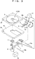
- FIG. 3 is an exploded perspective view showing the cleaning disk and the magneto-optical disk drive apparatus.
- FIG. 4 is a sectional view showing the major portions of a magneto-optical disk for ordinary recording.
- FIG. 5 is an explanatory view showing operation for recording on the cleaning disk.
- an optical head 1 is provided with an objective lens 2 for gathering and applying laser light to a magneto-optical disk 4 or a cleaning disk 23.
- the objective lens 2 is driven by an objective lens drive apparatus (not shown), for example, on two axes by virtue of electromagnetic drive so that an optical spot follows surface wobbling and eccentricity of the magneto-optical disk 4 or the cleaning disk 23.
- a magnetic head body 5 making sliding contact with the magneto-optical disk 4 and supplying a modulated magnetic field thereto is supported at one end of a suspension 13.
- the suspension 13 is made of a thin spring material, such as SUS304 or BeCu, to make the magnetic head body 5 sliding contact with the magneto-optical disk 4 or the cleaning disk 23 at all times even when surface wobbling occurs on the magneto-optical disk 4 or the cleaning disk 23.
- the other end of the suspension 13 is held by a fixed portion 13a, the fixed portion 13a is secured to a joint portion 14a, and the joint portion 14a is rotatably held by a connection portion 14 via a shaft 14b.
- the connection portion 14 is connected to the optical head 1.
- the magnetic head body 5 has a slider portion made of a resin having a high sliding performance, such as polyphenylene sulfide or liquid crystal polymer, and makes sliding contact with the magneto-optical disk 4 or the cleaning disk 23.
- the magnetic head body 5 is provided with a magnetic circuit (not shown) comprising a magnetic core and a coil, and generates a modulated magnetic field when a modulated current is supplied from a magnetic head drive circuit 17.
- Transfer shafts 15a and 15b are inserted into the optical head 1 and secured to a base 16.
- a spindle motor 8 is secured to the base 16.
- a turntable 7 is secured to the end of the rotation shaft of the spindle motor 8.
- the turntable 7 is provided with a permanent magnet for example and holds the magneto-optical disk 4 or the cleaning disk 23 by attracting a clamp hub made of a metal.
- a motor drive circuit 18 rotates and drives the spindle motor 8, thereby rotating the magneto-optical disk 4 or the cleaning disk 23.
- the magneto-optical disk 4 or the cleaning disk 23 is housed in a cartridge 6.
- a shutter (not shown) provided for the cartridge 6 opens, and recording/reproduction operation by the optical head 1 and the magnetic head 3 can be carried out.
- a disk substrate 12 is made of a resin, such as polycarbonate.
- An information layer 20 is made of a magnetic film capable of vertical magnetization and formed on the disk substrate 12 by the sputtering method or the like.
- a lubrication film 21 is made of a silicone-based lubricant for example. The thickness of the lubrication film 21 is for example generally 10 ⁇ m to 20 ⁇ m in the case of an MD.
- a disk substrate 12 is made of a resin, such as polycarbonate.
- An information layer 20 is made of a magnetic film capable of vertical magnetization and formed on the disk substrate 12 by the sputtering method or the like.
- a head-cleaning member 22 having the shape of a sheet is formed of woven cloth made of animal fiber, plant fiber, synthetic fiber, chemical fiber, etc. or nonwoven cloth. This head-cleaning member 22 is secured to the disk substrate 12 with an adhesive for example, and its thickness is for example about 0.2 mm to 0.4 mm in the case of an MD. Its coefficient of friction is about two to four times as high as that of the lubrication film 21.
- Lens cleaning members 27 are made of nylon fiber, carbon fiber, glass fiber, amide fiber and the like, individually or in combination.
- the lens-cleaning members 27 are secured to the disk substrate 12 with an adhesive for example and formed so that their brush-shaped ends make contact with the objective lens 2.
- a disk information area 31 used as an index area, a skip area 32 and a recording area 33 are formed on the information layer 20 from its inner circumference, and information (a current value) regarding a magnetic head drive current in the case of using the cleaning disk 23 is recorded beforehand in the disk information area 31.
- This information regarding the magnetic head drive current is formed as microscopic pits and projections on the disk substrate 12 for example.
- the cleaning disk 23 is rotatably housed in the cartridge 6 comprising an upper cartridge 26 and a lower cartridge 28.
- the cartridge 6 is provided with a disk detection groove 29; when the cartridge 6 is loaded into the magneto-optical disk drive apparatus, a disk detection switch 24 disposed on the base 16 turns "ON" and recognizes the disk as a recording disk.
- the optical head 1 When recording is carried out on the magneto-optical disk 4 or the cleaning disk 23 shown in FIGS. 1 to 5, while the above-mentioned magneto-optical disk 4 or cleaning disk 23 is rotated by the spindle motor 8, the optical head 1 emits a laser spot to one side of the information layer 20 to heat a recording area of the information layer 20 to Curie temperature or more.
- a current modulated by an information signal is supplied from the magnetic head drive circuit 17 to the coil of the magnetic head body 5, whereby a vertical magnetic field being directed from the magnetic core to the information layer 20 is generated, and an N or S magnetic field is thus applied.
- recording is carried out.
- the slider portion of the magnetic head body 5 makes sliding contact with the lubrication film 21 or the head-cleaning member 22.
- One cleaning operation of the magnetic head 3 becomes one recording operation of about 10 to 30 seconds in the case of an MD for example.
- the operation is recorded as a piece of music; when a cleaning operation is carried out next time, a recording operation is performed and recorded as the next piece of music.
- the slider portion of the magnetic head body 5 does not make sliding contact with an area on the head-cleaning member 22 again, with which the slider portion made sliding contact. This prevents dust and the like stuck to the cleaning layer from being stuck to the magnetic head body 5 again.
- L1 designates the recording area for the first piece of music
- L2 and L3 designate the recording areas for the second and third pieces of music, respectively.
- the optical head 1 first reads the disk information area 31.
- the magnitude of an appropriate modulated current to be supplied to the magnetic head 3 in the case when the cleaning disk 23 is used has been recorded in advance; according to the signal read by the optical head 1, information regarding the preset value of the modulated current is supplied to the magnetic head drive circuit 17, whereby the current supplied from the magnetic head drive circuit 17 to the magnetic head 3 is made larger than the current at the time when recording is carried out on the magneto-optical disk 4 (usually about 100 mA to 150 mA in the case of an MD).
- the modulated current is increased to the appropriate current value (usually about 250 mA to 400 mA in the case of an MD).
- the optical head 1 moves to a recording area 33 provided on the outer circumferential side of the skip area 32, and recording operation, that is, cleaning operation starts.
- the reproduction state of the magneto-optical disk drive apparatus is selected, whereby the optical head 1 moves to the skip area 32. Then, the lens-cleaning members 27 make rotating contact with the objective lens 2 to remove dust stuck to the objective lens 2.
- the information regarding the magnetic head drive current is provided in the disk information area 31 of the cleaning disk 23, and the information in the disk information area 31 is read by the optical head 1, whereby the magnetic head drive current can be made large when recording operation is carried out on the cleaning disk 23, and the magnetic head drive current can be made small when recording operation is carried out on the magneto-optical disk 4, an ordinary medium.
- the optical head 1 can read the magnetic head modulated current without providing any new detection mechanism, and power consumption and electromagnetic noise of the magneto-optical disk drive apparatus can be reduced.
- the appropriate value of the magnetic head drive current (modulated current) during cleaning can be read by the optical head 1 from the cleaning disk 23.
- the operation condition of the magneto-optical disk drive apparatus during cleaning can be set at an appropriate state depending on the cleaning disk 23.
- the appropriate value of the magnetic head drive current (modulated current) can be read without providing any special structure, whereby the structure of the magneto-optical disk drive apparatus does not become complicated.
- the appropriate value of the magnetic head drive current (modulated current) is read by the optical head 1, it is possible to discriminate between the cleaning disk 23 and the ordinary magneto-optical disk 4 without requiring any special configuration, whereby the structure of the magneto-optical disk drive apparatus does not become complicated for disk discrimination.
- a countermeasure can be taken by changing the appropriate value of the magnetic head drive current (modulated current) to be recorded on the cleaning disk in accordance therewith; even in the magneto-optical disk drive apparatus, by setting the operation condition depending on the appropriate value of the magnetic head drive current (modulated current), the operation condition of the magneto-optical disk drive apparatus during cleaning can be set at an appropriate state depending on the cleaning disk 23 at all times.
- FIG. 6 is a sectional view showing the major portions of a cleaning disk and a magneto-optical disk drive apparatus in accordance with a second embodiment of the present invention in a state of cleaning
- FIG. 7 is an exploded perspective view showing the cleaning disk and the magneto-optical disk drive apparatus.
- this embodiment differs from the first embodiment in that information regarding magnetic head drive current (a current value) and information regarding disk rotation speed (a value representing rotation speed) at the time when the cleaning disk is used have been recorded in the disk information area 34 of a cleaning disk 30 in advance.
- the optical head 1 first reads the disk information area 34.
- the information regarding the magnitude of a modulated current to be supplied to the magnetic head 3 and disk rotation speed in the case when the cleaning disk 30 is used has been recorded in advance; according to the signal read by the optical head 1, information regarding the preset value of the modulated current is supplied to the magnetic head drive circuit 17, and control information regarding the rotation speed of the cleaning disk 30 is sent to the motor drive circuit 18, whereby the current supplied from the magnetic head drive circuit 17 to the magnetic head 3 is made larger than the current in the case when recording operation is carried out on the magneto-optical disk 4, and the disk rotation speed is made lower (about 1/2 to 1/10 of the ordinary speed) than that in the case when the ordinary magneto-optical disk 4 is used.
- the value of the above-mentioned modulated current should only be set just as in the case of the previous embodiment.
- the optical head 1 moves to recording area 33 provided on the outer circumferential side of the skip area 32, and recording operation, that is, cleaning operation starts.
- the information regarding the magnetic head drive current and the information regarding the disk rotation speed are provided in the disk information area 34 of the cleaning disk 30, and the information in the disk information area 34 is read by the optical head 1, whereby the magnetic head drive current can be made large and the disk rotation speed can be made low when recording operation is carried out on the cleaning disk 30, and the magnetic head drive current can be made small and the disk rotation speed can be made high when recording operation is carried out on the magneto-optical disk 4 for ordinary recording/reproduction.
- the rotation speed of the magneto-optical disk during cleaning can be read by the optical head 1.
- the operation condition of the magneto-optical disk drive apparatus during cleaning can be set at an appropriate state depending on the cleaning disk 30.
- the rotation speed of the magneto-optical disk during cleaning can be read without providing any special structure, whereby the structure of the magneto-optical disk drive apparatus does not become complicated.
- the rotation speed of the magneto-optical disk during cleaning is read by the optical head 1, it is thus possible to discriminate between the cleaning disk 30 and the ordinary magneto-optical disk 4 without requiring any special configuration, whereby the structure of the magneto-optical disk drive apparatus does not become complicated for disk discrimination.
- a countermeasure can be taken by changing the appropriate value of the magnetic head drive current (modulated current) to be recorded on the cleaning disk 30 in accordance therewith; even in the magneto-optical disk drive apparatus, by setting the operation condition depending on the appropriate value of the magnetic head drive current (modulated current), the operation condition of the magneto-optical disk drive apparatus during cleaning can be set at an appropriate state depending on the cleaning disk 30 at all times.
- FIG. 8 is a sectional view showing the major portions of a cleaning disk and a magneto-optical disk drive apparatus in accordance with a third embodiment of the present invention in a state of cleaning.
- this embodiment differs from the first and second embodiments in that, in the disk information area 44 of a cleaning disk 40, information (an output power value) regarding the laser power of the optical head 1 at the time when the cleaning disk is used has been recorded in advance.
- the optical head 1 In cleaning operation, when the cleaning disk 40 is loaded into the magneto-optical disk drive apparatus, the optical head 1 first reads the disk information area 44. In this disk information area 44, the setting information of the power of laser emitted from the optical head 1 in the case when the cleaning disk 40 is used has been recorded in advance; the signal read by the optical head 1 is sent to an optical head drive circuit 47 as the setting information of the laser power. Hence, the laser power of the optical head 1 is controlled so that the laser power is made smaller than that during recording operation on the magneto-optical disk 4 shown in FIG. 7. The laser power at this time should preferably be equal to that during reproduction operation on the magneto-optical disk 4.
- the optical head 1 moves to a cleaning area 48 provided on the outer circumferential side of the skip area 32, and the magnetic head 3 starts recording state, that is, cleaning operation.
- the optical head 1 and the magnetic head 3 move to the disk information area 31, and information regarding the position wherein the cleaning operation was carried out is recorded. At this time, it is desired to additionally record information regarding the number of times the cleaning operation is carried out.
- the information regarding the laser power of the optical head 1 is provided in the disk information area 44 of the cleaning disk 40; therefore, by reading the information in the disk information area 44 by using the optical head 1, the laser power of the optical head 1 can be made smaller during the cleaning operation of the cleaning disk 40 than that during recording on the ordinary magneto-optical disk 4.
- the power consumption of the magneto-optical disk drive apparatus can be reduced even when the cleaning disk 40 is used.
- the appropriate value of the laser power of the optical head 1 during cleaning can be read by the optical head 1 from the cleaning disk 40.
- the operation condition of the magneto-optical disk drive apparatus during cleaning can be set at an appropriate state depending on the cleaning disk 40.
- the laser power of the optical head 1 during cleaning can be read without providing any special structure, whereby the structure of the magneto-optical disk drive apparatus does not become complicated.
- the laser power of the optical head 1 during cleaning is read by the optical head 1, it is possible to discriminate between the cleaning disk 40 and the ordinary magneto-optical disk 4 without requiring any special configuration, whereby the structure of the magneto-optical disk drive apparatus does not become complicated for disk discrimination.
- a countermeasure can be taken by changing the laser power of the optical head 1 during cleaning in accordance therewith; even in the magneto-optical disk drive apparatus, by setting the operation condition depending on the cleaning condition, the operation condition of the magneto-optical disk drive apparatus during cleaning can be set at an appropriate state depending on the cleaning disk 40 at all times.
- a recording current is supplied to the magnetic head 3; however, the current supply to the magnetic head 3 may be shut off.
- the power consumption of the magneto-optical disk drive apparatus during cleaning can be reduced further.
- FIGS. 9 and 10 A fourth embodiment of the present invention will be described below referring to FIGS. 9 and 10.
- lens-cleaning members 127 are disposed radially in the entire cleaning area of the cleaning disk 40. After the optical head 1 reads the information in the information area 44, cleaning operation is carried out in a cleaning area 148. In this case, in addition to the above-mentioned effects, the cleaning of the magnetic head 3 and the cleaning of the optical head 1 can be carried out simultaneously at all times.
- the laser light of the optical head 1 may be turned off during the above-mentioned cleaning operation.
- the spindle motor 8 should be subjected to rotation speed control by using an FG signal.
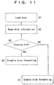
- FIG. 11 is a flowchart showing the cleaning operation of a cleaning disk and a magneto-optical disk drive apparatus in accordance with a fifth embodiment of the present invention.
- step S1 is a disk loading step.
- Step S2 is a disk information reading step.
- Step S3 is a cleaning disk discrimination step.
- Step S4 is a disk formatting disabling step.
- Step S5 is a disk formatting enabling step.
- this embodiment differs from the first, second, third and fourth embodiments in the following points: when a disk is loaded (at step S1), the optical head 1 reads the information area 44 of the cleaning disk 40 (at step S2), discrimination is made as to whether the disk is a cleaning disk or not according to the read information (at step S3), disk formatting is disabled when the disk is recognized as a cleaning disk (at step S4), and disk formatting is enabled in the other case (at step S5).
- the optical head 1 reads information in the information area 44.
- control information for magneto-optical disk drive apparatus such as magnetic head drive current control information, spindle motor rotation control information and laser power control information for the optical head 1 as well as information regarding the number of times the cleaning disk is used and the usage area thereof are written simultaneously in advance.
- the optical head 1 reads the information, and the magneto-optical disk drive apparatus recognizes that the loaded disk is a cleaning disk.
- the magneto-optical disk drive apparatus goes into a mode wherein disk-formatting operation for formatting the information area 44 is disabled.
- Pits for the above-mentioned magneto-optical disk control information may be formed in the disk in advance.
- the information regarding the usage state of the cleaning disk such as the number of times the cleaning disk is used and the usage area thereof, is required to be written by the magneto-optical disk drive apparatus; by disabling disk formatting, the user is prevented from erasing the above-mentioned information regarding the usage state of the cleaning disk by mistake.
- the information in the disk information area 44 is read by the optical head 1, and disk formatting is disabled when the magneto-optical disk drive apparatus discriminates and recognizes a cleaning disk.
- the user is prevented from erasing the information regarding the usage state of the cleaning disk by mistake.
- disk formatting is disabled when the magneto-optical disk drive apparatus recognizes the cleaning disk in this embodiment, in the case when all the cleaning areas are used, it is preferable that disk formatting should be enabled.
- the same cleaning disk can be used a plurality of times.
- an area wherein the number of times the cleaning disk is used is recorded should be provided in an area other than the information area 44 so that the information regarding the number of times the cleaning disk is used is not erased.
- the magneto-optical disk drive apparatus As a result of reading of the above-mentioned number of times by the magneto-optical disk drive apparatus, if the number is a certain value or more, it is desirable that the use of the above-mentioned cleaning disk should be disabled.
- a configuration for disabling disk formatting is described; however, it may be possible that at least writing or erasing of the information in the index area is disabled during cleaning. Conditions for rewriting or erasing the information in the index area can be considered just as in the case of the above-mentioned disk formatting.
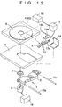
- FIG. 12 is an exploded perspective view showing a recording/reproduction apparatus in accordance with a sixth embodiment of the present invention.
- FIG. 13 is a side sectional view showing the major portions of a magnetic head and a magneto-optical disk (ordinary recording/reproduction disk) during ordinary recording operation.
- FIG. 14 is a side sectional view showing the major portions of a magnetic head cleaning disk and the magnetic head during magnetic head cleaning operation.
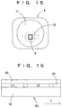
- FIG. 15 is a magnified view showing the major portions of the magnetic head.
- FIG. 16 is an explanatory view showing the operation of recording on the magnetic head cleaning disk.
- the optical head 1 is provided with the objective lens 2 for gathering and applying laser light to the magneto-optical disk 4 or a magnetic head cleaning disk 63.
- the head body 5 making sliding contact with the magneto-optical disk 4 and supplying a modulated magnetic field thereto is supported at one end of the suspension 13.
- the suspension 13 is made of a thin spring material, such as SUS304 or BeCu, to make the head body 5 sliding contact with the magneto-optical disk 4 at all times even when surface wobbling occurs on the magneto-optical disk 4.
- connection portion 14 is connected to the optical head 1.
- the magnetic head body 5 comprises the magnetic core 9, the coil 10 and the slider 11.
- the slider 11 is made of a resin having a high sliding performance, such as polyphenylene sulfide or liquid crystal polymer, and makes sliding contact with the magneto-optical disk 4 for ordinary recording/reproduction or the magnetic head cleaning disk 63.
- This slider 11 is formed so as to be integrated with the suspension 13.
- the magnetic core 9 has an E-shaped form, the open end of which faces toward the sliding face of the slider 11.
- the coil 10 is wound around and secured to the center pole of the magnetic core 9. Furthermore, the coil 10 is electrically joined to the suspension 13 having a feeding function, and generates a modulated magnetic field when a modulated current is supplied from the magnetic head drive circuit 17.
- the transfer shafts 15a and 15b are inserted into the optical head 1 and secured to the base 16.
- the spindle motor 8 is secured to the base 16.
- the turntable 7 is secured to the end of the rotation shaft of the spindle motor 8 to hold the magneto-optical disk 4 for ordinary recording/reproduction or the magnetic head cleaning disk 63.
- the motor drive circuit 18 rotates and drives the spindle motor 8, thereby rotating the magneto-optical disk 4 or the magnetic head cleaning disk 63.
- the magneto-optical disk 4 or the magnetic head cleaning disk 63 is housed in the cartridge 6.
- a shutter (not shown) provided for the cartridge 6 opens, and recording/reproduction operation by the optical head 1 and the magnetic head 3 can be carried out.
- a reflection sensor 59 detects the reflectivity of the face of the magneto-optical disk 4 or the magnetic head cleaning disk 63 making sliding contact with the magnetic head 3, thereby functioning as discrimination means for discriminating as to whether the disk medium is the magneto-optical disk 4 or the magnetic head cleaning disk 63;
- the sensor comprises an LED light-emitting portion and a light-receiving device for example. Light is then applied from the LED light-emitting portion to the sliding face of the magneto-optical disk 4 making sliding contact with the magnetic head through the shutter window of the cartridge 6, and its reflected light is received by the light-receiving device, whereby the magnitude of the level of the reflected light can be determined.
- the disk substrate 12 is formed of a resin, such as polycarbonate.
- a recording/reproduction layer (information layer) 60 is made of a magnetic film capable of vertical magnetization and formed on the disk substrate 12 by the sputtering method or the like.
- a lubrication film 61 is made of a silicone-based lubricant for example, and its thickness is for example generally 10 ⁇ m to 20 ⁇ m in the case of an MD.
- reference code X designates the movement direction of the disk.
- the disk substrate 12 is made of a resin, such as polycarbonate.
- the recording/reproduction layer 60 is made of a magnetic film capable of vertical magnetization and formed on the disk substrate 12 by the sputtering method or the like.
- a cleaning layer 62 is formed of woven cloth made of animal fiber, plant fiber, synthetic fiber, chemical fiber, etc. or nonwoven cloth. This cleaning layer 62 is secured to the disk substrate 12 with an adhesive for example, and its thickness is for example about 0.2 mm to 0.4 mm in the case of an MD. Furthermore, the coefficient of friction of the cleaning layer 62 is about two to four times as high as that of the lubrication film 61.
- reference code X designates the movement direction of the disk.
- the optical head 1 When recording is carried out on the magneto-optical disk 4 or the magnetic head cleaning disk 63 shown in FIGS. 12, 13 and 14, while the above-mentioned magneto-optical disk 4 or magnetic head cleaning disk 63 is rotated by the spindle motor 8, the optical head 1 emits a laser spot to one side of the recording/reproduction layer 60 to heat the recording area of the recording/reproduction layer 60 to Curie temperature or more.
- a current modulated by an information signal is supplied from the magnetic head drive circuit 17 to the coil 10 via the suspension 13, whereby a vertical magnetic field being directed from the end face of the central magnetic pole of the magnetic core 9 to the recording/reproduction layer 60 is generated, and an N or S magnetic field is thus applied.
- the slider 11 makes sliding contact with the lubrication film 61 or the cleaning layer 62.
- One cleaning operation of the magnetic head 3 becomes one recording operation of about 10 to 30 seconds in the case of an MD for example.
- the operation is recorded as a piece of music; when a cleaning operation is carried out next time, the recording operation is performed and recorded as the next piece of music.
- the slider 11 does not make sliding contact with an area on the cleaning layer 62 again, with which the slider 11 made sliding contact. This prevents dust and the like stuck to the cleaning layer from being stuck to the slider 11 again.
- reference code Y designates a radial direction.
- the light-receiving amount of the reflection sensor 59 reduces since the cleaning layer 62 is relatively apt to scatter and absorb light. Because of the reduction in the light-receiving amount, the reflection sensor 59 discriminates and recognizes that the disk medium is the magnetic head cleaning disk 63; when the light-receiving amount is large, the sensor discriminates and recognizes that the disk medium is the ordinary magneto-optical disk 4.
- the modulated current to be supplied from the magnetic head drive circuit 17 to the magnetic head 3 is made larger than that during recording operation on the ordinary magneto-optical disk 4.
- the modulated current to be supplied to the magnetic head 3 is made smaller than that during recording operation on the magnetic head cleaning disk 63.
- the reflection sensor 59 is provided to discriminate and recognize the type of disk medium, whereby the current value to be supplied from the magnetic head drive circuit 17 to the magnetic head 3 can be made different depending on whether recording operation is carried out on the magnetic head cleaning disk 63 or on the ordinary magneto-optical disk 4.
- the modulated current can be made large when recording operation is carried out on the magnetic head cleaning disk 63 during which the spacing between the magnetic head 3 and the recording/reproduction layer 60 is large, and the current can made small when recording operation is carried out on the ordinary magneto-optical disk 4 during which the spacing is small.
- power consumption and electromagnetic noise of the recording/reproduction apparatus can be reduced.
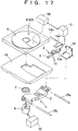
- FIG. 17 is an exploded perspective view showing a recording/reproduction apparatus in accordance with a seventh embodiment of the present invention.
- This embodiment differs from the sixth embodiment in that a CCD sensor 64 is used instead of the reflection sensor 59 as discrimination means to detect the color of the face of the disk medium making sliding contact with the magnetic head and to discriminate as to whether the disk medium is the magnetic head cleaning disk 63 or the ordinary magneto-optical disk 4.
- a CCD sensor 64 is used instead of the reflection sensor 59 as discrimination means to detect the color of the face of the disk medium making sliding contact with the magnetic head and to discriminate as to whether the disk medium is the magnetic head cleaning disk 63 or the ordinary magneto-optical disk 4.
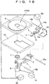
- FIG. 18 is an exploded perspective view showing a recording/reproduction apparatus in accordance with an eighth embodiment of the present invention.
- the recording/reproduction apparatus in accordance with this embodiment differs from those in accordance with the sixth and seventh embodiments in that, without detecting the reflectivity or color of the face of the disk medium making sliding contact with the magnetic head, as discrimination means, a sliding load at the time when the magnetic head makes sliding contact with the disk medium is detected to discriminate as to whether the disk medium is the magnetic head cleaning disk or the ordinary magneto-optical disk.
- a motor drive current detection circuit 65 is used to detect the drive current of the spindle motor 8 for rotating the disk medium as the sliding load at the time when the magnetic head makes sliding contact with the disk medium and to discriminate and recognize that the disk medium is the magnetic head cleaning disk.
- the motor drive current detection circuit 65 detects the drive current of the spindle motor 8 as described above, and determines that the disk medium is the magnetic head cleaning disk when the drive current is large and that the disk medium is the ordinary magneto-optical disk when the drive current is small.
- a magnetic head drive circuit 66 is used to supply the modulated current to the magnetic head 3.
- the coefficient of friction of the cleaning layer 62 of the magnetic head cleaning disk 63 is larger than that of the lubrication film 61 of the magneto-optical disk 4 as described above, when the magnetic head cleaning disk 63 is loaded into the recording/reproduction apparatus and when the magnetic head 3 starts making sliding contact with the cleaning layer 62, a rotation load to the spindle motor 8 becomes large, and its drive current also becomes large.
- the type of the disk medium is discriminated and recognized by detecting the drive current of the spindle motor 8 by using the motor drive current detection circuit 65 as shown in FIG. 18; only when the magnetic head cleaning disk 63 is used during which the spacing between the magnetic core 9 and the recording/reproduction layer 60 is large, the modulated current supplied from the magnetic head drive circuit 17 to the magnetic head 3 is increased.
- the motor drive current detection circuit 65 is provided to detect the drive current of the spindle motor 8 as the sliding load, whereby the magnetic head cleaning disk 63 can be discriminated from the ordinary magneto-optical disk 4 without adding any special sensor, the number of components can be reduced, and the price of the recording/reproduction apparatus can be lowered.
- FIG. 19 is an exploded perspective view showing a recording/reproduction apparatus in accordance with a ninth embodiment of the present invention.
- the recording/reproduction apparatus in accordance with the ninth embodiment differs from that in accordance with the eighth embodiment in that the information regarding the disk discriminated and recognized by a motor drive current detection circuit 67 is transmitted to a motor drive circuit 68 as well as the magnetic head drive circuit 66.
- the motor drive current detection circuit 67 detects the drive current of the spindle motor 8 just like the motor drive current detection circuit 65.
- the motor drive circuit 68 supplies the drive current to the spindle motor 8 and has a function of controlling the rotation speed of the spindle motor 8 depending on the discrimination and recognition result by the motor drive current detection circuit 67. More specifically, when the disk medium is the magnetic head cleaning disk 63, the rotation speed is lowered than that when the disk medium is the ordinary magneto-optical disk 4.
- the coefficient of friction of the cleaning layer 62 of the magnetic head cleaning disk 63 is larger than that of the lubrication film 61 of the magneto-optical disk 4 as described above, when the magnetic head cleaning disk 63 is loaded into the recording/reproduction apparatus and when the magnetic head 3 starts making sliding contact with the cleaning layer 62, a rotation load to the spindle motor 8 becomes large, and the drive current also becomes large.
- the type of the disk medium is discriminated and recognized by the motor drive current detection circuit 67; when the magnetic head cleaning disk 63 is used, the motor drive circuit 68 carries out control to rotate the spindle motor 8 at low speed. Therefore, wear of the slider 11 owing to the sliding of the cleaning layer 62 having a large coefficient of friction can be reduced.
- the motor drive current detection circuit 67 discriminates and recognizes the type of disk medium; when the magnetic head cleaning disk 63 is used, the spindle motor 8 is rotated at low speed, whereby wear of the slider 11 can be reduced, and the reliability of the recording/reproduction apparatus can be improved.
- the discrimination output of the reflection sensor 59 in accordance with the sixth embodiment or the CCD sensor 64 in accordance with the seventh embodiment may be used to control the motor drive circuit just as in the case of the ninth embodiment so that the spindle motor 8 is rotated at low speed when the magnetic head cleaning disk 63 is used.
- wear of the slider 11 owing to the sliding of the cleaning layer 62 having a large coefficient of friction can be reduced, and the reliability of the recording/reproduction apparatus can be improved.
Landscapes
- Physics & Mathematics (AREA)
- Optics & Photonics (AREA)
Abstract
The present invention provides a cleaning disk and a
magneto-optical disk drive apparatus being simple in
structure, adaptable to cleaning disks having various
specifications, low in power consumption, low in
electromagnetic noise, and preventing damage to the
magnetic head and the optical head; the cleaning disk
comprises a magneto-optical disk having an information
layer, and a head-cleaning member, provided on the magneto-optical
disk, for cleaning the magnetic head of the
magneto-optical disk drive apparatus, wherein information
regarding a magnetic head cleaning condition for setting
the operation condition of the magneto-optical disk drive
apparatus during cleaning of the magnetic head has been
recorded in advance on the information layer of the
magneto-optical disk. The magneto-optical disk drive
apparatus reads the information regarding the magnetic head
cleaning condition so as to set the operation condition
properly.
Description
The present invention relates to a cleaning disk and
a magneto-optical disk drive apparatus for removing dirt,
dust and other foreign particles stuck to the magnetic head
and optical head of an information recording/reproduction
apparatus.
Furthermore, the present invention relates to a
recording/reproduction apparatus, such as a floppy disk
drive (hereafter simply referred to as an FDD), a minidisk
apparatus (hereafter simply referred to as an MD apparatus)
and a magneto-optical data file apparatus, provided with a
sliding contact type magnetic head to apply a modulated
magnetic field to a recording medium. More particularly,
the present invention relates to a recording/reproduction
apparatus capable of carrying out recording and
reproduction on both types of disk media, that is, a
magnetic head cleaning disk having a cleaning layer on its
face making sliding contact with the magnetic head and an
ordinary recording/reproduction disk.
First, the background art of the cleaning disk and
the magneto-optical disk drive apparatus will be described.
Optical disk drive apparatuses are available as an
optical disk drive apparatus based on a thermal change
system wherein the crystals of the recording layer of an
optical disk are changed in phases by the heat of the laser
light of an optical head to carry out recording, typified
by a CD-R and a DVD, and a magneto-optical disk drive
apparatus based on a magneto-optical system wherein the
heat by the laser light of an optical head is combined with
the modulated magnetic field by a magnetic head to carry
out recording, typified by an MD.
The prior art will be described below by taking a
cleaning disk and a magneto-optical disk drive apparatus
based on the magneto-optical system as examples.
In a conventional magneto-optical disk drive
apparatus, an optical head for emitting a light beam
applied to a magneto-optical recording layer is disposed on
one side of a magneto-optical disk rotated by a disk
rotation mechanism (spindle motor), and a magnetic head for
applying an external magnetic field to the magneto-optical
recording layer is disposed on the other side so as to be
disposed opposite to the optical head.
The magneto-optical disk drive apparatus applies a
modulated magnetic field, the direction of which is
modulated depending on an information signal to be recorded
from the magnetic head, to the magneto-optical recording
layer of the magneto-optical disk to be rotated, and
gathers the light beam emitted from the optical head and
applies the light beam. After a portion heated to Curie
temperature or more by this application of the light beam
so as to be demagnetized is magnetized depending on the
direction of the magnetic field applied from the magnetic
head, the portion is cooled to Curie temperature or less by
the relative movement of the light beam owing to the
rotation of the magneto-optical disk, and the direction of
the magnetization is fixed, whereby the information signal
is recorded.
In this magneto-optical disk apparatus, when dust and
the like are stuck to the surfaces of the objective lens of
the optical head and the magnetic head relating to the
recording and reproduction of signals, the dust and the
like may prevent the laser light from reaching the magneto-optical
recording layer of the magneto-optical disk, and
may be stuck to the surface of the disk, thereby increasing
wear of the magneto-optical disk and making scratches,
furthermore, disturbing the spacing between the magnetic
head and the magneto-optical disk and increasing errors
owing to the disturbance.
A cleaning disk is used conventionally to remove
stain owing to dust and the like on the surfaces of the
objective lens and the magnetic head. An example of the
disk is disclosed in Japanese Laid-open Patent Application
Hei 7-6430. This disk is shown in FIG. 20. FIG. 20 is an
exploded perspective view showing the conventional cleaning
disk.
In the figure, a conventional disk 100 is used for an
MD apparatus, and just as in the case of a general writable
minidisk, lens-cleaning members 27 having the shape of a
raised brush fur bundle are disposed on the surface of a
magneto-optical disk 104 provided with a clamping hub 19 at
its center, and a head-cleaning member 22 having a nearly
sheet-like shape and capable of being made contact with the
end of the magnetic head at the recording position is
bonded in a predetermined radial range on the surface of
the disk disposed opposite to the magnetic head,.
The cleaning disk 100 is rotatably housed in the
cartridge 6 comprising an upper cartridge 26 and a lower
cartridge 28. The upper cartridge 26 is secured to the
lower cartridge 28 with screws 9. A disk detection groove
29 is formed in a part of the cartridge 6, whereby the
magneto-optical disk drive apparatus can detect that the
cleaning disk 100 is a recordable disk, just like the
magneto-optical disk for ordinary recording. This
cartridge 6 has a configuration common to the cartridge of
the magneto-optical disk for ordinary recording.
When the conventional cleaning disk 100 based on the
above-mentioned configuration is loaded into the magneto-optical
disk drive apparatus, the magneto-optical disk
drive apparatus determines that the disk is a recording
disk by using a disk detection switch and carries out
recording operation. At this time, the lens-cleaning
members 27 make contact with the objective lens of the
optical head, and the head-cleaning member on the opposite
side makes contact with the magnetic head, thereby cleaning
the objective lens and the magnetic head in accordance with
the rotation of the magneto-optical disk 104. After a
predetermined time, stop operation is carried out, and the
cleaning disk is taken out of the magneto-optical disk
drive apparatus, thereby completing cleaning.
If the magnetic head keeps sliding at the same area
of the above-mentioned head-cleaning member, the head-cleaning
member may be worn out, and dust and the like
removed from the sliding face of the magnetic head by the
head-cleaning member may be stuck again to the sliding face
at the end of the magnetic head.
Hence, when the magnetic head is cleaned by using the
cleaning disk in the case of an MD apparatus for example,
it is supposed that ordinary recording operation is carried
out during cleaning, and that the portion used for
recording, i.e., the portion used for cleaning, is recorded
as a first piece of music after the cleaning. Therefore,
when the cleaning disk is used next, the cleaning of the
magnetic head starts at the position for a second piece of
music. This configuration therefore prevents the magnetic
head from sliding at the same portion of the above-mentioned
cleaning member.
In the magneto-optical disk for ordinary recording
(ordinary recording/reproduction disk), a lubrication film
of about 10 µm to 20 µm is formed on the magneto-optical
recording layer. The spacing between the magnetic core of
the magnetic head and the above-mentioned magneto-optical
recording layer is about 0.01 mm to 0.1 mm.
On the other hand, in the magnetic head cleaning disk,
a head-cleaning member of 0.2 mm to 0.4 mm in thickness is
present on the magneto-optical recording film. Hence, the
spacing between the magnetic core and the magneto-optical
recording film is two times or more that of the ordinary
magneto-optical disk.
In addition, in the magneto-optical disk drive
apparatus, in order that the ordinary recording magneto-optical
disk and the cleaning disk can be used without
discrimination therebetween, a modulated current to be
supplied to the magnetic head is set larger so that
recording on the cleaning disk can be carried out without
problems, whereby the magnetic head is driven by the same
current value as that used during recording on the cleaning
disk, even during recording on the ordinary recording
magneto-optical disk.
In recent years, reducing the magnetic head drive
current has become a problem in order to extend battery
life in portable apparatuses, typified by a portable MD
apparatus for example, and to reduce electromagnetic noise
at the time when the magnetic head is driven.
However, in the above-mentioned conventional cleaning
disk and magneto-optical disk drive apparatus, it is
necessary to guarantee recording on the cleaning disk,
although the usage frequency of the cleaning disk having
the large spacing between the magnetic head and the
magneto-optical recording layer is less than that of the
ordinary magneto-optical disk. For this reason, the
modulated current of the magnetic head, that is, the drive
current of the magnetic head, cannot be reduced, thereby
causing a problem of making electric power saving difficult.
Furthermore, the rotation speed of the disk tends to
increase as the speed of information transfer increases; in
the above-mentioned conventional recording/reproduction
apparatus, when the cleaning disk is used, the sliding face
of the magnetic head may wear out and the objective lens
actuator of the optical head may break because of high
rotation speed, resulting in problems. To solve the above-mentioned
problems, the necessity for identifying cleaning
disk is intensified.
In a magneto-optical disk provided with a cartridge,
it is proposed that a type indication portion for
identifying the type of disk is provided by forming a notch
in a part of the cartridge as disclosed in Japanese Laid-open
Patent Application Hei 5-135541, for example.
However, a special-purpose detection switch is
required for the magneto-optical disk drive apparatus; this
increases the number of components for the magneto-optical
disk drive apparatus and makes the structure more
complicated; furthermore, when it is necessary to increase
the modulated current value of the magnetic head required
for recording because the specifications of the cleaning
disk, such as the thickness of the head-cleaning member,
are changed, no countermeasure can be taken, result in a
problem.
Next, the background art of the
recording/reproduction apparatus will be described.
As a recording/reproduction apparatus provided with a
magnetic head, a recording/reproduction apparatus based on
a magnetic recording/reproduction system, typified by an
FDD, wherein information is recorded/reproduced on a disk
medium by the magnetic head, is available. In addition, a
recording/reproduction apparatus based on a magneto-optical
recording/reproduction system, typified by an MD, wherein
information is recorded/reproduced on a disk medium by the
combination of the magnetic head and the optical head, is
also available.
The conventional art will be described below by
taking the recording/reproduction apparatus based on the
magneto-optical recording/reproduction system as an example.
In the conventional recording/reproduction apparatus,
an optical head for emitting a light beam applied to a
magneto-optical recording layer is disposed on one side of
a magneto-optical disk rotated by a disk rotation mechanism
(spindle motor), and a magnetic head for applying an
external magnetic field to the magneto-optical recording
layer is disposed on the other side so as to be disposed
opposite to the optical head.
The recording/reproduction apparatus applies a
modulated magnetic field, the direction of which is
modulated depending on an information signal to be recorded
from the magnetic head, to the magneto-optical recording
layer of the rotated magneto-optical disk, and gathers the
light beam emitted from the optical head and applies the
light beam.
After a portion heated to Curie temperature or more
by this application of the light beam so as to be
demagnetized is magnetized depending on the direction of
the magnetic field applied from the magnetic head, the
portion is cooled to Curie temperature or less by the
relative movement of the light beam owing to the rotation
of the magneto-optical disk, and the direction of the
magnetization is fixed, whereby the information signal is
recorded.
Since the magneto-optical disk may wobble when
rotated, a recording/reproduction apparatus provided with a
sliding contact type magnetic head for recording
information signals with the head body of the magnetic head
making contact with the disk is used for an MD for example.
In this recording/reproduction apparatus provided
with the sliding contact type magnetic head, dust and the
like deposited on the magneto-optical disk may be stuck to
the head sliding face of the magnetic head making sliding
contact with the magneto-optical disk during recording
operation; owing to the use for a long time, dust is
deposited on the head sliding face.
When this operation is repeated, stain owing to dust
and the like on the sliding face of the magnetic head may
increase wear of the magnetic head and the magneto-optical
disk and make scratches, furthermore, disturb the spacing
between the magnetic head and the magneto-optical disk and
increase errors owing to the disturbance.
In order to remove such stain owing to dust and the
like from the sliding face of the magnetic head, a cleaning
disk for cleaning the magnetic head, wherein a cleaning
layer formed of nonwoven cloth or the like is bonded to the
face of a magneto-optical disk making sliding contact with
the magnetic head, has been proposed so far (Japanese Laid-open
Patent Application Hei 6-274957).
When the above-mentioned cleaning disk is used for a
recording/reproduction apparatus, if the magnetic head
keeps sliding at the same area of the cleaning layer of the
above-mentioned cleaning disk, the cleaning layer may wear
out, and dust and the like removed from the sliding face of
the magnetic head by the cleaning layer may be stuck again
to the sliding face of the magnetic head.
Hence, even when the cleaning disk is used in the
case of an MD apparatus for example, it is supposed that
the ordinary recording operation is carried out during
cleaning, and that the portion used for recording, i.e.,
the portion used for cleaning, is recorded as a first piece
of music after the cleaning. Therefore, when the cleaning
disk is used next, the cleaning of the magnetic head starts
at the position of a second piece of music; this
configuration prevents the magnetic head from sliding at
the same portion of the above-mentioned cleaning layer.
In the magneto-optical disk for ordinary recording
(ordinary recording/reproduction disk), a lubrication film
of about 10 µm to 20 µm is formed on the magneto-optical
recording layer. The spacing between the magnetic core of
the magnetic head and the above-mentioned magneto-optical
recording film is about 0.01 mm to 0.1 mm.
On the other hand, in the cleaning disk, a head
cleaning layer of 0.2 mm to 0.4 mm in thickness is present
on the magneto-optical recording film. Hence, the spacing
between the magnetic core and the magneto-optical recording
film is two times or more that of the ordinary magneto-optical
disk.
In addition, in order that the ordinary magneto-optical
disk and the cleaning disk can be used without
discrimination therebetween, a modulated current to be
supplied to the magnetic head is set larger so that
recording on the cleaning disk can be carried out without
problems, whereby the magnetic head is driven by the same
current value as that used during recording on the cleaning
disk, even during recording on the ordinary magneto-optical
disk.
In recent years, reducing the magnetic head modulated
current has become a problem in order to extend battery
life in portable apparatuses, typified by a portable MD
apparatus for example, and to reduce electromagnetic noise
when the magnetic head is driven.
However, in the above-mentioned conventional
recording/reproduction apparatus, recording on the cleaning
disk is required to be guaranteed, although the usage
frequency of the cleaning disk having the large spacing
between the magnetic head and the magneto-optical recording
layer is extremely less than that of the ordinary magneto-optical
disk; therefore, the modulated current cannot be
reduced, thereby causing a problem of making electric power
saving difficult.
Furthermore, the rotation speed of the disk tends to
increase as the speed of information transfer increases; in
the above-mentioned conventional recording/reproduction
apparatus, when the cleaning disk is used, the sliding face
of the magnetic head may wear out because of high rotation
speed, resulting in problems.
An object of the present invention is to provide a
cleaning disk and a magneto-optical disk drive apparatus
being simple in structure, adaptable to cleaning disks
having various specifications, low in power consumption,
low in electromagnetic noise, and preventing damage to the
magnetic head and the optical head.
Furthermore, another object of the present invention
is to provide a recording/reproduction apparatus being low
in power consumption and low in electromagnetic noise.
Furthermore, still another object of the present
invention is to provide a recording/reproduction apparatus
capable of reducing wear on the sliding face of the
magnetic head.
The cleaning disk in accordance with the present
invention comprises a magneto-optical disk having an
information layer, and a head-cleaning member, provided on
the magneto-optical disk, for cleaning the magnetic head of
a magneto-optical disk drive apparatus, wherein information
regarding a magnetic head cleaning condition for setting
the operation condition of the magneto-optical disk drive
apparatus during cleaning of the magnetic head has been
recorded in advance on the information layer of the
magneto-optical disk.
The above-mentioned cleaning condition is for example
a recording condition during cleaning of the magnetic head,
more specifically, the magnetic head drive current
(modulated current) during cleaning, the rotation speed of
the magneto-optical disk during cleaning or the laser powel
of the optical head during cleaning. Furthermore, the
above-mentioned cleaning condition has been recorded in the
index area on the information layer of the magneto-optical
disk for example.
With this configuration, information regarding the
magnetic head cleaning condition in the case when the
cleaning disk is used, for example, an appropriate value of
the drive current (modulated current) of the magnetic head
during cleaning, an appropriate value of the rotation speed
of the magneto-optical disk during cleaning or an
appropriate value of the laser power of the optical head
during cleaning can be read by the optical head from the
cleaning disk. As a result, the operation condition of the
magneto-optical disk drive apparatus during cleaning can be
set at an appropriate state depending on the cleaning disk.
Furthermore, the information regarding the cleaning
condition can be read without providing any special
structure, whereby the structure of the magneto-optical
disk drive apparatus does not become complicated. Moreover,
since the information regarding the cleaning condition is
read by the optical head, it is possible to discriminate
between the cleaning disk and the ordinary magneto-optical
disk without requiring any special configuration, whereby
the structure of the magneto-optical disk drive apparatus
does not become complicated for disk discrimination.
Furthermore, even when the specifications of the cleaning
disk are modified, a countermeasure can be taken by
changing the cleaning condition to be recorded on the
cleaning disk in accordance therewith; even in the magneto-optical
disk drive apparatus, by setting the operation
condition depending on the cleaning condition, the
operation condition of the magneto-optical disk drive
apparatus during cleaning can be set at an appropriate
state depending on the cleaning disk at all times.
A magneto-optical disk drive apparatus in accordance
with the present invention has a magnetic head and an
optical head, wherein information regarding the cleaning
condition is read from a cleaning disk comprising a
magneto-optical disk and a magnetic head-cleaning member
provided thereon, on the information layer of which the
information regarding the magnetic head cleaning condition
is recorded, and an operation condition
(regarding/reproduction condition) during cleaning is
controlled on the basis of the cleaning condition.
With this configuration, information regarding the
magnetic head cleaning condition in the case when the
cleaning disk is used, for example, an appropriate value of
the drive current (modulated current) of the magnetic head
during cleaning, an appropriate value of the rotation speed
of the magneto-optical disk during cleaning or an
appropriate value of the laser power of the optical head
during cleaning can be read by the optical head from the
cleaning disk. As a result, the operation condition of the
magneto-optical disk drive apparatus during cleaning can be
set at an appropriate state depending on the cleaning disk.
Furthermore, the information regarding the cleaning
condition can be read without providing any special
structure, whereby the structure of the magneto-optical
disk drive apparatus does not become complicated. Moreover,
since the information regarding the cleaning condition is
read by the optical head, it is possible to discriminate
between the cleaning disk and the ordinary magneto-optical
disk without requiring any special configuration, whereby
the structure of the magneto-optical disk drive apparatus
does not become complicated for disk discrimination.
Furthermore, even when the specifications of the cleaning
disk are modified, by setting the operation condition
depending on the cleaning condition having been read, the
operation condition of the magneto-optical disk drive
apparatus during cleaning can be set at an appropriate
state depending on the cleaning disk at all times.
A first example of the above-mentioned cleaning
condition is the drive current of the magnetic head during
cleaning, and an example of the operation condition is the
drive current of the magnetic head corresponding to the
cleaning condition; the drive current of the magnetic head
during cleaning is made larger than that during ordinary
recording.
With this configuration, when recording is carried
out on the ordinary magneto-optical disk, the drive current
(modulated current) to be supplied to the magnetic head is
made smaller than that during recording on the cleaning
disk, whereby the power consumption and electromagnetic
noise of the magneto-optical disk drive apparatus can be
reduced.
A second example of the above-mentioned cleaning
condition is the rotation speed of the magneto-optical disk
during cleaning, and an example of the operation condition
is the rotation speed of the magneto-optical disk
corresponding to the cleaning condition; the rotation speed
of the magneto-optical disk during cleaning is made lower
than that during ordinary recording or reproduction.
With this configuration, damage to the optical head
and the magnetic head at the time when the cleaning disk is
used can be reduced.
A third example of the above-mentioned cleaning
condition is the laser power of the optical head during
cleaning, and an example of the operation condition is the
laser power of the optical head corresponding to the
cleaning condition; the laser power of the optical head
during cleaning is made lower than that during ordinary
recording.
With this configuration, the power consumption of the
magneto-optical disk drive apparatus at the time when the
cleaning disk is used can be reduced.
Furthermore, in the above-mentioned magneto-optical
disk drive apparatus, the laser power of the optical head
may be used as the laser power for reproduction during
cleaning, and cleaning may be carried out while the
magnetic head is made sliding contact with the cleaning
disk, and then information designating the area of the
cleaning disk used during the cleaning may be recorded in
the index area on the information layer of the cleaning
disk.
With this configuration, the power consumption of the
magneto-optical disk drive apparatus during cleaning can be
reduced, and the usable remaining area and the number of
usage times of the cleaning disk can be grasped from the
information in the index area.
Furthermore, in the above-mentioned magneto-optical
disk drive apparatus, disk formatting may be disabled
during cleaning.
With this configuration, information regarding the
usable remaining area and the number of usage times of the
cleaning disk is prevented from being erased or changed by
mistake.
Furthermore, in the above-mentioned magneto-optical
disk drive apparatus, at least the rewriting or erasing of
the information in the index area may be disabled during
cleaning.
With this configuration, in the case when information
regarding the usable remaining area and the number of usage
times of the cleaning disk is described in the index area,
the information regarding the usable remaining area and the
number of usage times of the cleaning disk is prevented
from being erased or changed by mistake.
A first recording/reproduction apparatus in
accordance with the present invention comprising a magnetic
head and capable of using a magnetic head cleaning disk
having a cleaning layer on a face making sliding contact
with the magnetic head as well as an ordinary
recording/reproduction disk as a disk medium, further
comprising discrimination means for discriminating and
recognizing that the disk medium is the magnetic head
cleaning disk, and magnetic head drive means for making the
current supplied to the magnetic head when the disk medium
is the magnetic head cleaning disk larger than the current
supplied to the magnetic head when the disk medium is the
ordinary magneto-optical disk on the basis of the
discrimination result of the discrimination means.
With this configuration, the discrimination means for
discriminating and recognizing the magnetic head cleaning
disk having the cleaning layer on the face making sliding
contact with the magnetic head is provided, and the
modulated current of the magnetic head when the magnetic
head cleaning disk is used is made larger than the
modulated current when the ordinary recording/reproduction
disk is used, whereby the modulated current supplied to the
magnetic head at the time when recording is carried out on
the ordinary recording/reproduction disk can be made
smaller than that at the time when recording is carried out
on the magnetic head cleaning disk, and the power
consumption and electromagnetic noise of the
recording/reproduction apparatus can be reduced.
A second recording/reproduction apparatus in
accordance with the present invention comprising a magnetic
head and capable of using a magnetic head cleaning disk
having a cleaning layer on a face making sliding contact
with the magnetic head as well as an ordinary
recording/reproduction disk as a disk medium, further
comprising discrimination means for discriminating and
recognizing that the disk medium is the magnetic head
cleaning disk, and disk medium drive means for making the
rotation speed of the disk medium when the disk medium is
the magnetic head cleaning disk lower than the rotation
speed of the disk medium when the disk medium is the
ordinary magneto-optical disk on the basis of the
discrimination result of the discrimination means.
With this configuration, the disk rotation speed when
the magnetic head cleaning disk is used is made lower than
that when the ordinary magneto-optical disk is used,
whereby wear of the sliding face of the magnetic head can
be reduced, and the reliability of the
recording/reproduction apparatus can be improved.
A third recording/reproduction apparatus in
accordance with the present invention comprising a magnetic
head and capable of using a magnetic head cleaning disk
having a cleaning layer on a face making sliding contact
with the magnetic head as well as an ordinary
recording/reproduction disk as a disk medium, further
comprising discrimination means for discriminating and
recognizing that the disk medium is the magnetic head
cleaning disk, magnetic head drive means for making the
current supplied to the magnetic head when the disk medium
is the magnetic head cleaning disk larger than the current
supplied to the magnetic head when the disk medium is the
ordinary magneto-optical disk on the basis of the
discrimination result of the discrimination means, and disk
medium drive means for making the rotation speed of the
disk medium when the disk medium is the magnetic head
cleaning disk lower than the rotation speed of the disk
medium when the disk medium is the ordinary magneto-optical
disk on the basis of the discrimination result of the
discrimination means.
With this configuration, the modulated current of the
magnetic head at the time when recording is carried out on
the ordinary recording/reproduction disk is made smaller
than that at the time when recording is carried out on the
magnetic head cleaning disk, and the power consumption and
electromagnetic noise of the recording/reproduction
apparatus can be reduced. In addition, the disk rotation
speed when the magnetic head cleaning disk is used is made
lower than that when the ordinary magneto-optical disk is
used, whereby wear of the sliding face of the magnetic head
can be reduced, and the reliability of the
recording/reproduction apparatus can be improved.
In the above-mentioned first, second or third
recording/reproduction apparatus, the discrimination means
discriminates and recognizes that the disk medium is the
magnetic head cleaning disk by detecting, for example, the
reflectivity or color of the face of the disk medium making
sliding contact with the magnetic head.
Furthermore, in the above-mentioned first, second or
third recording/reproduction apparatus, the discrimination
means discriminates and recognizes that the disk medium is
the magnetic head cleaning disk by detecting, for example,
the sliding load of the magnetic head making sliding
contact with the disk medium.
In particular, it is preferable that the drive
current of the spindle motor for rotating the disk medium
should be detected as the sliding load. With this
configuration, it is possible to discriminate between the
magnetic head cleaning disk and the ordinary
recording/reproduction disk without adding any special-purpose
sensor, whereby the price of the
recording/reproduction apparatus can be lowered.
Embodiments of the present invention will be
described below referring to the drawings.
FIG. 1 is a sectional view showing the major portions
of a cleaning disk and a magneto-optical disk drive
apparatus in accordance with a first embodiment of the
present invention in a state of cleaning. FIG. 2 is an
exploded perspective view showing the cleaning disk. FIG.
3 is an exploded perspective view showing the cleaning disk
and the magneto-optical disk drive apparatus. FIG. 4 is a
sectional view showing the major portions of a magneto-optical
disk for ordinary recording. FIG. 5 is an
explanatory view showing operation for recording on the
cleaning disk.
In FIGS. 1 to 5, an optical head 1 is provided with
an objective lens 2 for gathering and applying laser light
to a magneto-optical disk 4 or a cleaning disk 23.
The objective lens 2 is driven by an objective lens
drive apparatus (not shown), for example, on two axes by
virtue of electromagnetic drive so that an optical spot
follows surface wobbling and eccentricity of the magneto-optical
disk 4 or the cleaning disk 23.
In a magnetic head 3, a magnetic head body 5 making
sliding contact with the magneto-optical disk 4 and
supplying a modulated magnetic field thereto is supported
at one end of a suspension 13. The suspension 13 is made
of a thin spring material, such as SUS304 or BeCu, to make
the magnetic head body 5 sliding contact with the magneto-optical
disk 4 or the cleaning disk 23 at all times even
when surface wobbling occurs on the magneto-optical disk 4
or the cleaning disk 23. The other end of the suspension
13 is held by a fixed portion 13a, the fixed portion 13a is
secured to a joint portion 14a, and the joint portion 14a
is rotatably held by a connection portion 14 via a shaft
14b. Furthermore, the connection portion 14 is connected
to the optical head 1.
The magnetic head body 5 has a slider portion made of
a resin having a high sliding performance, such as
polyphenylene sulfide or liquid crystal polymer, and makes
sliding contact with the magneto-optical disk 4 or the
cleaning disk 23. The magnetic head body 5 is provided
with a magnetic circuit (not shown) comprising a magnetic
core and a coil, and generates a modulated magnetic field
when a modulated current is supplied from a magnetic head
drive circuit 17.
When the cartridge 6 is loaded into the magneto-optical
disk drive apparatus, a shutter (not shown)
provided for the cartridge 6 opens, and
recording/reproduction operation by the optical head 1 and
the magnetic head 3 can be carried out.
Next, the structure of the disk will be described.
First, the magneto-optical disk 4 for
recording/reproduction will be described referring to FIG.
4. A disk substrate 12 is made of a resin, such as
polycarbonate. An information layer 20 is made of a
magnetic film capable of vertical magnetization and formed
on the disk substrate 12 by the sputtering method or the
like. A lubrication film 21 is made of a silicone-based
lubricant for example. The thickness of the lubrication
film 21 is for example generally 10 µm to 20 µm in the case
of an MD.
Next, the cleaning disk 23 will be described
referring to FIG. 1. A disk substrate 12 is made of a
resin, such as polycarbonate. An information layer 20 is
made of a magnetic film capable of vertical magnetization
and formed on the disk substrate 12 by the sputtering
method or the like. A head-cleaning member 22 having the
shape of a sheet is formed of woven cloth made of animal
fiber, plant fiber, synthetic fiber, chemical fiber, etc.
or nonwoven cloth. This head-cleaning member 22 is secured
to the disk substrate 12 with an adhesive for example, and
its thickness is for example about 0.2 mm to 0.4 mm in the
case of an MD. Its coefficient of friction is about two to
four times as high as that of the lubrication film 21.
A disk information area 31 used as an index area, a
skip area 32 and a recording area 33 are formed on the
information layer 20 from its inner circumference, and
information (a current value) regarding a magnetic head
drive current in the case of using the cleaning disk 23 is
recorded beforehand in the disk information area 31.
This information regarding the magnetic head drive
current is formed as microscopic pits and projections on
the disk substrate 12 for example.
The cleaning disk 23 is rotatably housed in the
cartridge 6 comprising an upper cartridge 26 and a lower
cartridge 28. The cartridge 6 is provided with a disk
detection groove 29; when the cartridge 6 is loaded into
the magneto-optical disk drive apparatus, a disk detection
switch 24 disposed on the base 16 turns "ON" and recognizes
the disk as a recording disk.
Next, the operation of the above-mentioned magneto-optical
disk drive apparatus will be described. When
recording is carried out on the magneto-optical disk 4 or
the cleaning disk 23 shown in FIGS. 1 to 5, while the
above-mentioned magneto-optical disk 4 or cleaning disk 23
is rotated by the spindle motor 8, the optical head 1 emits
a laser spot to one side of the information layer 20 to
heat a recording area of the information layer 20 to Curie
temperature or more. At the same time, a current modulated
by an information signal is supplied from the magnetic head
drive circuit 17 to the coil of the magnetic head body 5,
whereby a vertical magnetic field being directed from the
magnetic core to the information layer 20 is generated, and
an N or S magnetic field is thus applied. As a result,
recording is carried out.
At this time, the slider portion of the magnetic head
body 5 makes sliding contact with the lubrication film 21
or the head-cleaning member 22.
One cleaning operation of the magnetic head 3 becomes
one recording operation of about 10 to 30 seconds in the
case of an MD for example. As shown in FIG. 5, each time a
cleaning operation is carried out, the operation is
recorded as a piece of music; when a cleaning operation is
carried out next time, a recording operation is performed
and recorded as the next piece of music. In other words,
the slider portion of the magnetic head body 5 does not
make sliding contact with an area on the head-cleaning
member 22 again, with which the slider portion made sliding
contact. This prevents dust and the like stuck to the
cleaning layer from being stuck to the magnetic head body 5
again. In FIG. 5, L1 designates the recording area for the
first piece of music, and L2 and L3 designate the recording
areas for the second and third pieces of music,
respectively.
In the above-mentioned magnetic cleaning operation,
when the magnetic head cleaning disk 23 is loaded into the
magneto-optical disk drive apparatus, the optical head 1
first reads the disk information area 31. In this disk
information area 31, the magnitude of an appropriate
modulated current to be supplied to the magnetic head 3 in
the case when the cleaning disk 23 is used has been
recorded in advance; according to the signal read by the
optical head 1, information regarding the preset value of
the modulated current is supplied to the magnetic head
drive circuit 17, whereby the current supplied from the
magnetic head drive circuit 17 to the magnetic head 3 is
made larger than the current at the time when recording is
carried out on the magneto-optical disk 4 (usually about
100 mA to 150 mA in the case of an MD). In other words,
the modulated current is increased to the appropriate
current value (usually about 250 mA to 400 mA in the case
of an MD).
Then, the optical head 1 moves to a recording area 33
provided on the outer circumferential side of the skip area
32, and recording operation, that is, cleaning operation
starts.
By the above-mentioned operation, dust stuck to the
magnetic head body 5 is wiped off and removed by the head-cleaning
member 22, and recording operation on the
information layer 20 is carried out.
Furthermore, when the objective lens 2 is cleaned,
the reproduction state of the magneto-optical disk drive
apparatus is selected, whereby the optical head 1 moves to
the skip area 32. Then, the lens-cleaning members 27 make
rotating contact with the objective lens 2 to remove dust
stuck to the objective lens 2.
As described above, in the cleaning disk and the
magneto-optical disk drive apparatus in accordance with the
first embodiment of the preset invention, the information
regarding the magnetic head drive current is provided in
the disk information area 31 of the cleaning disk 23, and
the information in the disk information area 31 is read by
the optical head 1, whereby the magnetic head drive current
can be made large when recording operation is carried out
on the cleaning disk 23, and the magnetic head drive
current can be made small when recording operation is
carried out on the magneto-optical disk 4, an ordinary
medium.
Hence, in the case when the cleaning disk 23 is used,
the optical head 1 can read the magnetic head modulated
current without providing any new detection mechanism, and
power consumption and electromagnetic noise of the magneto-optical
disk drive apparatus can be reduced.
In addition, the appropriate value of the magnetic
head drive current (modulated current) during cleaning can
be read by the optical head 1 from the cleaning disk 23.
As a result, the operation condition of the magneto-optical disk drive apparatus during cleaning can be set at an appropriate state depending on thecleaning disk 23.
Furthermore, the appropriate value of the magnetic head drive current (modulated current) can be read without providing any special structure, whereby the structure of the magneto-optical disk drive apparatus does not become complicated. Moreover, since the appropriate value of the magnetic head drive current (modulated current) is read by theoptical head 1, it is possible to discriminate between
the cleaning disk 23 and the ordinary magneto-optical disk
4 without requiring any special configuration, whereby the
structure of the magneto-optical disk drive apparatus does
not become complicated for disk discrimination.
Furthermore, even when the specifications of thecleaning
disk 23 are modified, a countermeasure can be taken by
changing the appropriate value of the magnetic head drive
current (modulated current) to be recorded on the cleaning
disk in accordance therewith; even in the magneto-optical
disk drive apparatus, by setting the operation condition
depending on the appropriate value of the magnetic head
drive current (modulated current), the operation condition
of the magneto-optical disk drive apparatus during cleaning
can be set at an appropriate state depending on the
cleaning disk 23 at all times.
As a result, the operation condition of the magneto-optical disk drive apparatus during cleaning can be set at an appropriate state depending on the
Furthermore, the appropriate value of the magnetic head drive current (modulated current) can be read without providing any special structure, whereby the structure of the magneto-optical disk drive apparatus does not become complicated. Moreover, since the appropriate value of the magnetic head drive current (modulated current) is read by the
Furthermore, even when the specifications of the
FIG. 6 is a sectional view showing the major portions
of a cleaning disk and a magneto-optical disk drive
apparatus in accordance with a second embodiment of the
present invention in a state of cleaning, and FIG. 7 is an
exploded perspective view showing the cleaning disk and the
magneto-optical disk drive apparatus.
Referring to FIGS. 6 and 7, this embodiment differs
from the first embodiment in that information regarding
magnetic head drive current (a current value) and
information regarding disk rotation speed (a value
representing rotation speed) at the time when the cleaning
disk is used have been recorded in the disk information
area 34 of a cleaning disk 30 in advance.
Next, operation will be described. In cleaning
operation, when the cleaning disk 30 is loaded into the
magneto-optical disk drive apparatus, the optical head 1
first reads the disk information area 34. In this disk
information area 34, the information regarding the
magnitude of a modulated current to be supplied to the
magnetic head 3 and disk rotation speed in the case when
the cleaning disk 30 is used has been recorded in advance;
according to the signal read by the optical head 1,
information regarding the preset value of the modulated
current is supplied to the magnetic head drive circuit 17,
and control information regarding the rotation speed of the
cleaning disk 30 is sent to the motor drive circuit 18,
whereby the current supplied from the magnetic head drive
circuit 17 to the magnetic head 3 is made larger than the
current in the case when recording operation is carried out
on the magneto-optical disk 4, and the disk rotation speed
is made lower (about 1/2 to 1/10 of the ordinary speed)
than that in the case when the ordinary magneto-optical
disk 4 is used. The value of the above-mentioned modulated
current should only be set just as in the case of the
previous embodiment.
Then, the optical head 1 moves to recording area 33
provided on the outer circumferential side of the skip area
32, and recording operation, that is, cleaning operation
starts.
Since the details of the cleaning operation for the
magnetic head 3 and the cleaning operation for the
objective lens 2 are similar to those in the first
embodiment, the explanations of them are omitted here.
As described above, in the cleaning disk and the
magneto-optical disk drive apparatus in accordance with the
second embodiment of the preset invention, the information
regarding the magnetic head drive current and the
information regarding the disk rotation speed are provided
in the disk information area 34 of the cleaning disk 30,
and the information in the disk information area 34 is read
by the optical head 1, whereby the magnetic head drive
current can be made large and the disk rotation speed can
be made low when recording operation is carried out on the
cleaning disk 30, and the magnetic head drive current can
be made small and the disk rotation speed can be made high
when recording operation is carried out on the magneto-optical
disk 4 for ordinary recording/reproduction.
Hence, it is possible to prevent wear of the magnetic
head, damage of the objective lens and deformation of the
wire suspension for supporting the objective lens during
cleaning operation; in addition to the effects of the first
embodiment, the reliability of the devices is improved.
In addition, the rotation speed of the magneto-optical
disk during cleaning can be read by the optical
head 1. As a result, the operation condition of the
magneto-optical disk drive apparatus during cleaning can be
set at an appropriate state depending on the cleaning disk
30. Furthermore, the rotation speed of the magneto-optical
disk during cleaning can be read without providing any
special structure, whereby the structure of the magneto-optical
disk drive apparatus does not become complicated.
Moreover, since the rotation speed of the magneto-optical
disk during cleaning is read by the optical head 1, it is
thus possible to discriminate between the cleaning disk 30
and the ordinary magneto-optical disk 4 without requiring
any special configuration, whereby the structure of the
magneto-optical disk drive apparatus does not become
complicated for disk discrimination. Furthermore, even
when the specifications of the cleaning disk 30 are
modified, a countermeasure can be taken by changing the
appropriate value of the magnetic head drive current
(modulated current) to be recorded on the cleaning disk 30
in accordance therewith; even in the magneto-optical disk
drive apparatus, by setting the operation condition
depending on the appropriate value of the magnetic head
drive current (modulated current), the operation condition
of the magneto-optical disk drive apparatus during cleaning
can be set at an appropriate state depending on the
cleaning disk 30 at all times.
FIG. 8 is a sectional view showing the major portions
of a cleaning disk and a magneto-optical disk drive
apparatus in accordance with a third embodiment of the
present invention in a state of cleaning.
Referring to FIG. 8, this embodiment differs from the
first and second embodiments in that, in the disk
information area 44 of a cleaning disk 40, information (an
output power value) regarding the laser power of the
optical head 1 at the time when the cleaning disk is used
has been recorded in advance.
Next, operation will be described. In cleaning
operation, when the cleaning disk 40 is loaded into the
magneto-optical disk drive apparatus, the optical head 1
first reads the disk information area 44. In this disk
information area 44, the setting information of the power
of laser emitted from the optical head 1 in the case when
the cleaning disk 40 is used has been recorded in advance;
the signal read by the optical head 1 is sent to an optical
head drive circuit 47 as the setting information of the
laser power. Hence, the laser power of the optical head 1
is controlled so that the laser power is made smaller than
that during recording operation on the magneto-optical disk
4 shown in FIG. 7. The laser power at this time should
preferably be equal to that during reproduction operation
on the magneto-optical disk 4.
Then, the optical head 1 moves to a cleaning area 48
provided on the outer circumferential side of the skip area
32, and the magnetic head 3 starts recording state, that is,
cleaning operation.
By the above-mentioned operation, dust stuck to the
magnetic head body 5 is wiped off and removed by the head-cleaning
member 22.
After the cleaning operation, the optical head 1 and
the magnetic head 3 move to the disk information area 31,
and information regarding the position wherein the cleaning
operation was carried out is recorded. At this time, it is
desired to additionally record information regarding the
number of times the cleaning operation is carried out.
As described above, in the cleaning disk and the
magneto-optical disk drive apparatus in accordance with the
third embodiment 3 of the preset invention, the information
regarding the laser power of the optical head 1 is provided
in the disk information area 44 of the cleaning disk 40;
therefore, by reading the information in the disk
information area 44 by using the optical head 1, the laser
power of the optical head 1 can be made smaller during the
cleaning operation of the cleaning disk 40 than that during
recording on the ordinary magneto-optical disk 4.
Hence, the power consumption of the magneto-optical
disk drive apparatus can be reduced even when the cleaning
disk 40 is used.
In addition, the appropriate value of the laser power
of the optical head 1 during cleaning can be read by the
optical head 1 from the cleaning disk 40. As a result, the
operation condition of the magneto-optical disk drive
apparatus during cleaning can be set at an appropriate
state depending on the cleaning disk 40. Furthermore, the
laser power of the optical head 1 during cleaning can be
read without providing any special structure, whereby the
structure of the magneto-optical disk drive apparatus does
not become complicated. Moreover, since the laser power of
the optical head 1 during cleaning is read by the optical
head 1, it is possible to discriminate between the cleaning
disk 40 and the ordinary magneto-optical disk 4 without
requiring any special configuration, whereby the structure
of the magneto-optical disk drive apparatus does not become
complicated for disk discrimination. Furthermore, even
when the specifications of the cleaning disk 40 are
modified, a countermeasure can be taken by changing the
laser power of the optical head 1 during cleaning in
accordance therewith; even in the magneto-optical disk
drive apparatus, by setting the operation condition
depending on the cleaning condition, the operation
condition of the magneto-optical disk drive apparatus
during cleaning can be set at an appropriate state
depending on the cleaning disk 40 at all times.
In this embodiment, a recording current is supplied
to the magnetic head 3; however, the current supply to the
magnetic head 3 may be shut off. In this case, in addition
to the above-mentioned effects, the power consumption of
the magneto-optical disk drive apparatus during cleaning
can be reduced further.
A fourth embodiment of the present invention will be
described below referring to FIGS. 9 and 10.
As shown in FIGS. 9 and 10, lens-cleaning members 127
are disposed radially in the entire cleaning area of the
cleaning disk 40. After the optical head 1 reads the
information in the information area 44, cleaning operation
is carried out in a cleaning area 148. In this case, in
addition to the above-mentioned effects, the cleaning of
the magnetic head 3 and the cleaning of the optical head 1
can be carried out simultaneously at all times.
Furthermore, the laser light of the optical head 1
may be turned off during the above-mentioned cleaning
operation. In this case, it is desired that the spindle
motor 8 should be subjected to rotation speed control by
using an FG signal.
FIG. 11 is a flowchart showing the cleaning operation
of a cleaning disk and a magneto-optical disk drive
apparatus in accordance with a fifth embodiment of the
present invention. In FIG. 11, step S1 is a disk loading
step. Step S2 is a disk information reading step. Step S3
is a cleaning disk discrimination step. Step S4 is a disk
formatting disabling step. Step S5 is a disk formatting
enabling step.
Referring to FIG. 12, this embodiment differs from
the first, second, third and fourth embodiments in the
following points: when a disk is loaded (at step S1), the
optical head 1 reads the information area 44 of the
cleaning disk 40 (at step S2), discrimination is made as to
whether the disk is a cleaning disk or not according to the
read information (at step S3), disk formatting is disabled
when the disk is recognized as a cleaning disk (at step S4),
and disk formatting is enabled in the other case (at step
S5).
Next, the operation of this embodiment will be
described.
When the cleaning disk 40 shown in FIG. 9 is loaded
into the magneto-optical disk drive apparatus, the optical
head 1 reads information in the information area 44.
In the information area 44 of the cleaning disk 40,
control information for magneto-optical disk drive
apparatus, such as magnetic head drive current control
information, spindle motor rotation control information and
laser power control information for the optical head 1 as
well as information regarding the number of times the
cleaning disk is used and the usage area thereof are
written simultaneously in advance. The optical head 1
reads the information, and the magneto-optical disk drive
apparatus recognizes that the loaded disk is a cleaning
disk.
Then, the magneto-optical disk drive apparatus goes
into a mode wherein disk-formatting operation for
formatting the information area 44 is disabled.
Pits for the above-mentioned magneto-optical disk
control information may be formed in the disk in advance.
However, the information regarding the usage state of the
cleaning disk, such as the number of times the cleaning
disk is used and the usage area thereof, is required to be
written by the magneto-optical disk drive apparatus; by
disabling disk formatting, the user is prevented from
erasing the above-mentioned information regarding the usage
state of the cleaning disk by mistake.
Since the cleaning operation is similar to that in
the first, second and third embodiments, its explanation is
omitted here.
As described above, in the cleaning disk and the
magneto-optical disk drive apparatus in accordance with the
third embodiment 5 of the preset invention, the information
in the disk information area 44 is read by the optical head
1, and disk formatting is disabled when the magneto-optical
disk drive apparatus discriminates and recognizes a
cleaning disk.
Hence, the user is prevented from erasing the
information regarding the usage state of the cleaning disk
by mistake.
Other effects of this embodiment are similar to those
of the preceding embodiments.
Although disk formatting is disabled when the
magneto-optical disk drive apparatus recognizes the
cleaning disk in this embodiment, in the case when all the
cleaning areas are used, it is preferable that disk
formatting should be enabled.
In this case, in addition to the above-mentioned
effects, the same cleaning disk can be used a plurality of
times.
Furthermore, it is desirable that an area wherein the
number of times the cleaning disk is used is recorded
should be provided in an area other than the information
area 44 so that the information regarding the number of
times the cleaning disk is used is not erased.
In this case, in addition to the above-mentioned
effects, it is sure that the number of times the cleaning
disk is used can be grasped.
Furthermore, as a result of reading of the above-mentioned
number of times by the magneto-optical disk drive
apparatus, if the number is a certain value or more, it is
desirable that the use of the above-mentioned cleaning disk
should be disabled.
In this case, in addition to the above-mentioned
effects, it is possible to prevent the use of a cleaning
disk whose service life has ended, and the reliability of
the devices is improved.
In the above-mentioned embodiment, a configuration
for disabling disk formatting is described; however, it may
be possible that at least writing or erasing of the
information in the index area is disabled during cleaning.
Conditions for rewriting or erasing the information in the
index area can be considered just as in the case of the
above-mentioned disk formatting. With this configuration,
in the case when information regarding the usable remaining
area of the cleaning disk and information regarding the
number of usage times thereof are written in the index area,
the information regarding the usable remaining area of the
cleaning disk and the information regarding the number of
usage times thereof are prevented from being erased or
changed by mistake.
FIG. 12 is an exploded perspective view showing a
recording/reproduction apparatus in accordance with a sixth
embodiment of the present invention. FIG. 13 is a side
sectional view showing the major portions of a magnetic
head and a magneto-optical disk (ordinary
recording/reproduction disk) during ordinary recording
operation. FIG. 14 is a side sectional view showing the
major portions of a magnetic head cleaning disk and the
magnetic head during magnetic head cleaning operation. FIG.
15 is a magnified view showing the major portions of the
magnetic head. FIG. 16 is an explanatory view showing the
operation of recording on the magnetic head cleaning disk.
In FIGS. 12 to 16, the optical head 1 is provided
with the objective lens 2 for gathering and applying laser
light to the magneto-optical disk 4 or a magnetic head
cleaning disk 63. In the magnetic head 3, the head body 5
making sliding contact with the magneto-optical disk 4 and
supplying a modulated magnetic field thereto is supported
at one end of the suspension 13. The suspension 13 is made
of a thin spring material, such as SUS304 or BeCu, to make
the head body 5 sliding contact with the magneto-optical
disk 4 at all times even when surface wobbling occurs on
the magneto-optical disk 4. The other end of the
suspension 13 is held by the fixed portion 13a, the fixed
portion 13a is secured to the joint portion 14a, and the
joint portion 14a is rotatably held by the connection
portion 14 via the shaft 14b. Furthermore, the connection
portion 14 is connected to the optical head 1.
The magnetic head body 5 comprises the magnetic core
9, the coil 10 and the slider 11. The slider 11 is made of
a resin having a high sliding performance, such as polyphenylene
sulfide or liquid crystal polymer, and makes
sliding contact with the magneto-optical disk 4 for
ordinary recording/reproduction or the magnetic head
cleaning disk 63. This slider 11 is formed so as to be
integrated with the suspension 13. As shown in FIG. 13,
the magnetic core 9 has an E-shaped form, the open end of
which faces toward the sliding face of the slider 11. The
coil 10 is wound around and secured to the center pole of
the magnetic core 9. Furthermore, the coil 10 is
electrically joined to the suspension 13 having a feeding
function, and generates a modulated magnetic field when a
modulated current is supplied from the magnetic head drive
circuit 17.
The transfer shafts 15a and 15b are inserted into the
optical head 1 and secured to the base 16. The spindle
motor 8 is secured to the base 16. The turntable 7 is
secured to the end of the rotation shaft of the spindle
motor 8 to hold the magneto-optical disk 4 for ordinary
recording/reproduction or the magnetic head cleaning disk
63. Furthermore, the motor drive circuit 18 rotates and
drives the spindle motor 8, thereby rotating the magneto-optical
disk 4 or the magnetic head cleaning disk 63. The
magneto-optical disk 4 or the magnetic head cleaning disk
63 is housed in the cartridge 6.
When the cartridge 6 is loaded into the
recording/reproduction apparatus, a shutter (not shown)
provided for the cartridge 6 opens, and
recording/reproduction operation by the optical head 1 and
the magnetic head 3 can be carried out.
A reflection sensor 59 detects the reflectivity of
the face of the magneto-optical disk 4 or the magnetic head
cleaning disk 63 making sliding contact with the magnetic
head 3, thereby functioning as discrimination means for
discriminating as to whether the disk medium is the
magneto-optical disk 4 or the magnetic head cleaning disk
63; the sensor comprises an LED light-emitting portion and
a light-receiving device for example. Light is then
applied from the LED light-emitting portion to the sliding
face of the magneto-optical disk 4 making sliding contact
with the magnetic head through the shutter window of the
cartridge 6, and its reflected light is received by the
light-receiving device, whereby the magnitude of the level
of the reflected light can be determined.
Next, the structure of the disk medium will be
described.
First, the magneto-optical disk 4 for ordinary
recording/reproduction will be described referring to FIG.
13. The disk substrate 12 is formed of a resin, such as
polycarbonate. A recording/reproduction layer (information
layer) 60 is made of a magnetic film capable of vertical
magnetization and formed on the disk substrate 12 by the
sputtering method or the like. A lubrication film 61 is
made of a silicone-based lubricant for example, and its
thickness is for example generally 10 µm to 20 µm in the
case of an MD. In FIG. 13, reference code X designates the
movement direction of the disk.
Next, the magnetic head cleaning disk 63 will be
described referring to FIG. 14. The disk substrate 12 is
made of a resin, such as polycarbonate. The
recording/reproduction layer 60 is made of a magnetic film
capable of vertical magnetization and formed on the disk
substrate 12 by the sputtering method or the like. A
cleaning layer 62 is formed of woven cloth made of animal
fiber, plant fiber, synthetic fiber, chemical fiber, etc.
or nonwoven cloth. This cleaning layer 62 is secured to
the disk substrate 12 with an adhesive for example, and its
thickness is for example about 0.2 mm to 0.4 mm in the case
of an MD. Furthermore, the coefficient of friction of the
cleaning layer 62 is about two to four times as high as
that of the lubrication film 61. In FIG. 14, reference
code X designates the movement direction of the disk.
Next, the operations of the above-mentioned
recording/reproduction apparatus will be described.
When recording is carried out on the magneto-optical
disk 4 or the magnetic head cleaning disk 63 shown in FIGS.
12, 13 and 14, while the above-mentioned magneto-optical
disk 4 or magnetic head cleaning disk 63 is rotated by the
spindle motor 8, the optical head 1 emits a laser spot to
one side of the recording/reproduction layer 60 to heat the
recording area of the recording/reproduction layer 60 to
Curie temperature or more. At the same time, a current
modulated by an information signal is supplied from the
magnetic head drive circuit 17 to the coil 10 via the
suspension 13, whereby a vertical magnetic field being
directed from the end face of the central magnetic pole of
the magnetic core 9 to the recording/reproduction layer 60
is generated, and an N or S magnetic field is thus applied.
By the above-mentioned operation, recording is carried out.
At this time, the slider 11 makes sliding contact
with the lubrication film 61 or the cleaning layer 62.
One cleaning operation of the magnetic head 3 becomes
one recording operation of about 10 to 30 seconds in the
case of an MD for example. As shown in FIG. 16, each time
a cleaning operation is carried out, the operation is
recorded as a piece of music; when a cleaning operation is
carried out next time, the recording operation is performed
and recorded as the next piece of music. In other words,
the slider 11 does not make sliding contact with an area on
the cleaning layer 62 again, with which the slider 11 made
sliding contact. This prevents dust and the like stuck to
the cleaning layer from being stuck to the slider 11 again.
In FIG. 16, reference code Y designates a radial direction.
In the above-mentioned head cleaning operation, when
the magnetic head cleaning disk 63 is loaded into the
recording/reproduction apparatus, the light-receiving
amount of the reflection sensor 59 reduces since the
cleaning layer 62 is relatively apt to scatter and absorb
light. Because of the reduction in the light-receiving
amount, the reflection sensor 59 discriminates and
recognizes that the disk medium is the magnetic head
cleaning disk 63; when the light-receiving amount is large,
the sensor discriminates and recognizes that the disk
medium is the ordinary magneto-optical disk 4.
When the disk medium is the magnetic head cleaning
disk 63 on the basis of the discrimination result by the
reflection sensor 59, the modulated current to be supplied
from the magnetic head drive circuit 17 to the magnetic
head 3 is made larger than that during recording operation
on the ordinary magneto-optical disk 4. Conversely, when
recording is carried out on the ordinary magneto-optical
disk 4, the modulated current to be supplied to the
magnetic head 3 is made smaller than that during recording
operation on the magnetic head cleaning disk 63.
By the above-mentioned operation, dust stuck to the
slider 11 is wiped off and removed, and recording operation
on the recording/reproduction layer 60 is carried out.
As described above, in the recording/reproduction
apparatus in accordance with the sixth embodiment of the
present invention, the reflection sensor 59 is provided to
discriminate and recognize the type of disk medium, whereby
the current value to be supplied from the magnetic head
drive circuit 17 to the magnetic head 3 can be made
different depending on whether recording operation is
carried out on the magnetic head cleaning disk 63 or on the
ordinary magneto-optical disk 4. In other words, the
modulated current can be made large when recording
operation is carried out on the magnetic head cleaning disk
63 during which the spacing between the magnetic head 3 and
the recording/reproduction layer 60 is large, and the
current can made small when recording operation is carried
out on the ordinary magneto-optical disk 4 during which the
spacing is small. As a result, power consumption and
electromagnetic noise of the recording/reproduction
apparatus can be reduced.
FIG. 17 is an exploded perspective view showing a
recording/reproduction apparatus in accordance with a
seventh embodiment of the present invention.
This embodiment differs from the sixth embodiment in
that a CCD sensor 64 is used instead of the reflection
sensor 59 as discrimination means to detect the color of
the face of the disk medium making sliding contact with the
magnetic head and to discriminate as to whether the disk
medium is the magnetic head cleaning disk 63 or the
ordinary magneto-optical disk 4.
Even in this embodiment, effects similar to those of
the sixth embodiment can be obtained.
FIG. 18 is an exploded perspective view showing a
recording/reproduction apparatus in accordance with an
eighth embodiment of the present invention.
The recording/reproduction apparatus in accordance
with this embodiment differs from those in accordance with
the sixth and seventh embodiments in that, without
detecting the reflectivity or color of the face of the disk
medium making sliding contact with the magnetic head, as
discrimination means, a sliding load at the time when the
magnetic head makes sliding contact with the disk medium is
detected to discriminate as to whether the disk medium is
the magnetic head cleaning disk or the ordinary magneto-optical
disk.
More specifically, instead of the reflection sensor
59 or the CCD sensor 64, a motor drive current detection
circuit 65 is used to detect the drive current of the
spindle motor 8 for rotating the disk medium as the sliding
load at the time when the magnetic head makes sliding
contact with the disk medium and to discriminate and
recognize that the disk medium is the magnetic head
cleaning disk.
In FIG. 18, the motor drive current detection circuit
65 detects the drive current of the spindle motor 8 as
described above, and determines that the disk medium is the
magnetic head cleaning disk when the drive current is large
and that the disk medium is the ordinary magneto-optical
disk when the drive current is small. A magnetic head
drive circuit 66 is used to supply the modulated current to
the magnetic head 3.
Since the coefficient of friction of the cleaning
layer 62 of the magnetic head cleaning disk 63 is larger
than that of the lubrication film 61 of the magneto-optical
disk 4 as described above, when the magnetic head cleaning
disk 63 is loaded into the recording/reproduction apparatus
and when the magnetic head 3 starts making sliding contact
with the cleaning layer 62, a rotation load to the spindle
motor 8 becomes large, and its drive current also becomes
large.
Hence, the type of the disk medium is discriminated
and recognized by detecting the drive current of the
spindle motor 8 by using the motor drive current detection
circuit 65 as shown in FIG. 18; only when the magnetic head
cleaning disk 63 is used during which the spacing between
the magnetic core 9 and the recording/reproduction layer 60
is large, the modulated current supplied from the magnetic
head drive circuit 17 to the magnetic head 3 is increased.
As described above, in the recording/reproduction
apparatus in accordance with the eighth embodiment, in
addition to the effects of the sixth embodiment, the motor
drive current detection circuit 65 is provided to detect
the drive current of the spindle motor 8 as the sliding
load, whereby the magnetic head cleaning disk 63 can be
discriminated from the ordinary magneto-optical disk 4
without adding any special sensor, the number of components
can be reduced, and the price of the recording/reproduction
apparatus can be lowered.
FIG. 19 is an exploded perspective view showing a
recording/reproduction apparatus in accordance with a ninth
embodiment of the present invention.
The recording/reproduction apparatus in accordance
with the ninth embodiment differs from that in accordance
with the eighth embodiment in that the information
regarding the disk discriminated and recognized by a motor
drive current detection circuit 67 is transmitted to a
motor drive circuit 68 as well as the magnetic head drive
circuit 66.
In FIG. 19, the motor drive current detection circuit
67 detects the drive current of the spindle motor 8 just
like the motor drive current detection circuit 65. The
motor drive circuit 68 supplies the drive current to the
spindle motor 8 and has a function of controlling the
rotation speed of the spindle motor 8 depending on the
discrimination and recognition result by the motor drive
current detection circuit 67. More specifically, when the
disk medium is the magnetic head cleaning disk 63, the
rotation speed is lowered than that when the disk medium is
the ordinary magneto-optical disk 4.
Since the coefficient of friction of the cleaning
layer 62 of the magnetic head cleaning disk 63 is larger
than that of the lubrication film 61 of the magneto-optical
disk 4 as described above, when the magnetic head cleaning
disk 63 is loaded into the recording/reproduction apparatus
and when the magnetic head 3 starts making sliding contact
with the cleaning layer 62, a rotation load to the spindle
motor 8 becomes large, and the drive current also becomes
large.
Hence, the type of the disk medium is discriminated
and recognized by the motor drive current detection circuit
67; when the magnetic head cleaning disk 63 is used, the
motor drive circuit 68 carries out control to rotate the
spindle motor 8 at low speed. Therefore, wear of the
slider 11 owing to the sliding of the cleaning layer 62
having a large coefficient of friction can be reduced.
As described above, in the recording/reproduction
apparatus in accordance with the ninth embodiment, in
addition to the effects of the eighth embodiment, the motor
drive current detection circuit 67 discriminates and
recognizes the type of disk medium; when the magnetic head
cleaning disk 63 is used, the spindle motor 8 is rotated at
low speed, whereby wear of the slider 11 can be reduced,
and the reliability of the recording/reproduction apparatus
can be improved.
The discrimination output of the reflection sensor 59
in accordance with the sixth embodiment or the CCD sensor
64 in accordance with the seventh embodiment may be used to
control the motor drive circuit just as in the case of the
ninth embodiment so that the spindle motor 8 is rotated at
low speed when the magnetic head cleaning disk 63 is used.
In this case, just as in the case of the ninth embodiment,
wear of the slider 11 owing to the sliding of the cleaning
layer 62 having a large coefficient of friction can be
reduced, and the reliability of the recording/reproduction
apparatus can be improved.
Furthermore, in the above-mentioned ninth embodiment,
it is possible to consider an embodiment wherein the
control of the magnetic head drive circuit 66 by using the
discrimination output of the motor drive current detection
circuit 67 is omitted. In this case, it is possible to
obtain the effects of reducing wear of the slider 11 and
improving the reliability of the recording/reproduction
apparatus, although the effects of reducing power
consumption and electromagnetic noise of the
recording/reproduction apparatus cannot be obtained.
Even a recording/reproduction apparatus based on a
magnetic recording/reproduction system, typified by an FDD,
can also be accomplished by eliminating the optical head 1
from the above-mentioned sixth to ninth embodiments; hence,
its explanation is omitted here.
Claims (18)
- A cleaning disk comprising a magneto-optical disk having an information layer, and a head-cleaning member, provided on said magneto-optical disk, for cleaning the magnetic head of a magneto-optical disk drive apparatus,
wherein information regarding a magnetic head cleaning condition for setting the operation condition of said magneto-optical disk drive apparatus during cleaning of said magnetic head has been recorded in advance on the information layer of said magneto-optical disk. - A cleaning disk in accordance with claim 1, wherein said cleaning condition is a recording condition during cleaning of said magnetic head.
- A cleaning disk in accordance with claim 1, wherein said cleaning condition is the rotation speed of said magneto-optical disk during cleaning.
- A cleaning disk in accordance with claim 1, wherein said cleaning condition is the laser power of the optical head during cleaning.
- A cleaning disk in accordance with claim 1, wherein information regarding said cleaning condition is recorded in the index area on the information layer of said magneto-optical disk.
- A magneto-optical disk drive apparatus having a magnetic head and an optical head,
wherein information regarding said cleaning condition is read from a cleaning disk comprising a magneto-optical disk and a magnetic head-cleaning member provided thereon, on the information layer of which the information regarding said magnetic head cleaning condition is recorded, and an operation condition during cleaning is controlled on the basis of said cleaning condition. - A magneto-optical disk drive apparatus in accordance with claim 6, wherein said cleaning condition is the drive current of said magnetic head during cleaning, said operation condition is said drive current of said magnetic head, and said drive current of said magnetic head is made larger during cleaning than that during ordinary recording.
- A magneto-optical disk drive apparatus in accordance with claim 6, wherein said cleaning condition is said disk rotation speed during cleaning, said operation condition is said disk rotation speed, and said disk rotation speed during cleaning is made lower than that during ordinary recording or reproduction.
- A magneto-optical disk drive apparatus in accordance with claim 6, wherein said cleaning condition is the laser power of said optical head during cleaning, said operation condition is said laser power of said optical head, and said laser power of said optical head during cleaning is made lower than that during ordinary recording.
- A magneto-optical disk drive apparatus in accordance with claim 6, wherein said laser power of said optical head is used as the laser power for reproduction during cleaning, and cleaning is carried out while said magnetic head is made sliding contact with said cleaning disk, and then information designating the area of said cleaning disk used during said cleaning is recorded in the index area on the information layer of said cleaning disk.
- A magneto-optical disk drive apparatus in accordance with claim 6, wherein disk formatting is disabled during cleaning.
- A magneto-optical disk drive apparatus in accordance with claim 6, wherein at least the rewriting or erasing of the information in said index area is disabled during cleaning.
- A recording/reproduction apparatus comprising a magnetic head and capable of using a magnetic head cleaning disk having a cleaning layer on a face making sliding contact with said magnetic head as well as an ordinary recording/reproduction disk as a disk medium,
further comprising discrimination means for discriminating and recognizing that said disk medium is said magnetic head cleaning disk, and magnetic head drive means for making the current supplied to said magnetic head when said disk medium is said magnetic head cleaning disk larger than the current supplied to said magnetic head when said disk medium is said ordinary magneto-optical disk on the basis of the discrimination result of said discrimination means. - A recording/reproduction apparatus comprising a magnetic head and capable of using a magnetic head cleaning disk having a cleaning layer on a face making sliding contact with said magnetic head as well as an ordinary recording/reproduction disk as a disk medium,
further comprising discrimination means for discriminating and recognizing that said disk medium is said magnetic head cleaning disk, and disk medium drive means for making the rotation speed of said disk medium when said disk medium is said magnetic head cleaning disk lower than the rotation speed of said disk medium when said disk medium is said ordinary magneto-optical disk on the basis of the discrimination result of said discrimination means. - A recording/reproduction apparatus comprising a magnetic head and capable of using a magnetic head cleaning disk having a cleaning layer on a face making sliding contact with said magnetic head as well as an ordinary recording/reproduction disk as a disk medium,
further comprising discrimination means for discriminating and recognizing that said disk medium is said magnetic head cleaning disk, magnetic head drive means for making the current supplied to said magnetic head when said disk medium is said magnetic head cleaning disk larger than the current supplied to said magnetic head when said disk medium is said ordinary magneto-optical disk on the basis of the discrimination result of said discrimination means, and disk medium drive means for making the rotation speed of said disk medium when said disk medium is said magnetic head cleaning disk lower than the rotation speed of said disk medium when said disk medium is said ordinary magneto-optical disk on the basis of the discrimination result of said discrimination means. - A recording/reproduction apparatus in accordance with claims 13, 14 or 15, wherein said discrimination means discriminates and recognizes that said disk medium is said magnetic head cleaning disk by detecting, the reflectivity or color of the face of said disk medium making sliding contact with said magnetic head.
- A recording/reproduction apparatus in accordance with claims 13, 14 or 15, wherein said discrimination means discriminates and recognizes that said disk medium is said magnetic head cleaning disk by detecting, the sliding load of said magnetic head making sliding contact with said disk medium.
- A recording/reproduction apparatus in accordance with claim 17, wherein the drive current of a spindle motor for rotating said disk medium is detected as said sliding load.
Applications Claiming Priority (5)
| Application Number | Priority Date | Filing Date | Title |
|---|---|---|---|
| JP33437799 | 1999-11-25 | ||
| JP33437799 | 1999-11-25 | ||
| JP2000190894 | 2000-06-26 | ||
| JP2000190894 | 2000-06-26 | ||
| PCT/JP2000/008190 WO2001039182A1 (en) | 1999-11-25 | 2000-11-20 | Cleaning disc, magneto-optical disc apparatus and recording/reproducing apparatus |
Publications (2)
| Publication Number | Publication Date |
|---|---|
| EP1150278A1 true EP1150278A1 (en) | 2001-10-31 |
| EP1150278A4 EP1150278A4 (en) | 2006-11-22 |
Family
ID=26574826
Family Applications (1)
| Application Number | Title | Priority Date | Filing Date |
|---|---|---|---|
| EP00976381A Withdrawn EP1150278A4 (en) | 1999-11-25 | 2000-11-20 | CLEANING PLATE, MAGNETO-OPTICAL PLATE UNIT AND RECORDING / PLAYBACK PLAYER |
Country Status (4)
| Country | Link |
|---|---|
| US (2) | US6711102B1 (en) |
| EP (1) | EP1150278A4 (en) |
| AU (1) | AU1418201A (en) |
| WO (1) | WO2001039182A1 (en) |
Families Citing this family (9)
| Publication number | Priority date | Publication date | Assignee | Title |
|---|---|---|---|---|
| JP3088608U (en) * | 2002-03-14 | 2002-09-20 | オリエント測器コンピュータ株式会社 | Hard disk drive recording data erasing device |
| JP2009519561A (en) * | 2005-12-16 | 2009-05-14 | コーニンクレッカ フィリップス エレクトロニクス エヌ ヴィ | Method for cleaning optical surface of refractive element for near-field optical scanning device, and cleaning device for cleaning optical surface of refractive element for near-field optical scanning device |
| RU2334280C1 (en) * | 2007-04-02 | 2008-09-20 | Дмитрий Анатольевич Беляев | Device for cleaning spindle lodgement of device for reading and-or data recording on compact discs |
| US7544252B1 (en) | 2008-08-20 | 2009-06-09 | International Business Machines Corporation | Spring actuated slotted DIMM contact cleaning device |
| JP5653522B2 (en) * | 2011-07-15 | 2015-01-14 | パナソニックIpマネジメント株式会社 | Information recording / reproducing apparatus, cleaning tape, and optical pickup cleaning method |
| JP5849212B2 (en) * | 2011-12-02 | 2016-01-27 | パナソニックIpマネジメント株式会社 | Lens cleaner and optical disk apparatus |
| US10121581B2 (en) * | 2014-09-29 | 2018-11-06 | Apple Inc. | Method for magnetizing multiple zones in a monolithic piece of magnetic material |
| US9858953B1 (en) * | 2017-03-31 | 2018-01-02 | Seagate Technology Llc | Method of removing head contamination during contact detection |
| US10199067B1 (en) * | 2018-03-23 | 2019-02-05 | Seagate Technology Llc | Adaptive cleaning of a media surface responsive to a mechanical disturbance event |
Family Cites Families (41)
| Publication number | Priority date | Publication date | Assignee | Title |
|---|---|---|---|---|
| CA1086857A (en) * | 1975-08-26 | 1980-09-30 | Tsutomu Sugisaki | Cleaning jackets |
| GB1586055A (en) * | 1978-03-29 | 1981-03-18 | Burroughs Corp | Cleaning disc assembly for magnetic transducers |
| US4499516A (en) * | 1982-02-08 | 1985-02-12 | Perfect Data Corporation | Cleaning disk with opaque ring |
| US4594617A (en) * | 1982-08-11 | 1986-06-10 | Canon Kabushiki Kaisha | Method and apparatus for cleaning a recording and/or reproducing head |
| US4586100A (en) * | 1983-03-18 | 1986-04-29 | International Jensen Incorporated | Cleaning disc |
| KR940005567B1 (en) * | 1985-07-23 | 1994-06-20 | 히다찌마구세루 가부시기가이샤 | Disc cartridge |
| EP0269290B1 (en) * | 1986-11-05 | 1991-11-06 | Joseph Frederick Fritsch | A cleaning device |
| US4870636A (en) * | 1987-03-25 | 1989-09-26 | Kabushiki Kaisha Toshiba | Optical information processing apparatus and cleaning cartridge |
| JPS6472375A (en) * | 1987-09-14 | 1989-03-17 | Hitachi Maxell | Disk cartridge |
| US4814926A (en) * | 1987-09-28 | 1989-03-21 | Polaroid Corporation | Flexible disk cassette |
| JPH0636546Y2 (en) * | 1989-01-19 | 1994-09-21 | 花王株式会社 | Magnetic disk cartridge |
| JPH02206010A (en) * | 1989-02-02 | 1990-08-15 | Fujitsu Ltd | Magnetic disk device |
| JPH0547019A (en) * | 1991-08-08 | 1993-02-26 | Kyocera Corp | Disk cleaning device for cleaning disk cartridge and disk recording / reproducing device |
| JPH05151747A (en) * | 1991-11-28 | 1993-06-18 | Kubota Corp | Disk Cleaner |
| JP2810824B2 (en) * | 1992-07-03 | 1998-10-15 | 富士通株式会社 | Optical disk drive |
| US5488596A (en) * | 1993-02-17 | 1996-01-30 | Martin; Robert D. | Cleaning device that does not engage the disc drive spindle |
| JPH06274957A (en) * | 1993-03-24 | 1994-09-30 | Sony Corp | Cleaning disk for magnetic head for magneto-optical recording |
| JP2819492B2 (en) | 1993-06-21 | 1998-10-30 | ティーディーケイ株式会社 | Cleaning disc |
| DE4419477C2 (en) * | 1993-06-03 | 2002-10-24 | Tdk Corp | Cleaning disc cassette |
| JPH076430A (en) * | 1993-06-21 | 1995-01-10 | Tdk Corp | Cleaning disk |
| US5467238A (en) * | 1993-07-06 | 1995-11-14 | Quantum Corporation | Cleaning apparatus for heads of data storage disks |
| JP3423421B2 (en) * | 1993-12-27 | 2003-07-07 | 富士通株式会社 | Library device |
| JPH08167125A (en) | 1994-12-08 | 1996-06-25 | Matsushita Electric Ind Co Ltd | Disk media for head cleaning |
| JPH09128721A (en) | 1995-10-31 | 1997-05-16 | Sony Corp | Cleaning tape cassette and magnetic recording / reproducing apparatus using the cleaning tape cassette |
| JP2000510635A (en) * | 1995-11-20 | 2000-08-15 | アイオメガ コーポレイション | Head cleaning performed by loading the head at low speed |
| JPH09147437A (en) | 1995-11-22 | 1997-06-06 | Sony Corp | Cleaning disk, disk cartridge thereof, and magneto-optical disk device |
| US6324158B1 (en) * | 1996-02-28 | 2001-11-27 | Mitsubishi Denki Kabushiki Kaisha | Disk cartridge |
| JPH09245390A (en) * | 1996-03-08 | 1997-09-19 | Sony Corp | Cleaning disc and cleaning disc cartridge |
| JPH10340496A (en) * | 1997-02-17 | 1998-12-22 | Maakisu:Kk | Cleaning device |
| JPH1091926A (en) * | 1997-04-08 | 1998-04-10 | Tdk Corp | Cleaning cassette for optical disk device |
| JPH1145417A (en) | 1997-07-28 | 1999-02-16 | Tdk Corp | Cleaning cartridge for mint disk player |
| JPH11176035A (en) | 1997-12-12 | 1999-07-02 | Maakisu:Kk | Cleaning equipment |
| JPH11185420A (en) | 1997-12-18 | 1999-07-09 | Maakisu:Kk | Cleaning equipment |
| JPH11213356A (en) * | 1998-01-12 | 1999-08-06 | Internatl Business Mach Corp <Ibm> | Head deposit removing method and information recording and reproducing device |
| JPH11328764A (en) * | 1998-05-15 | 1999-11-30 | Tdk Corp | Cleaning disk |
| JP2000011339A (en) | 1998-06-19 | 2000-01-14 | Nippon Seiki Hoseki Kogyo Kk | Head cleaner for magneto-optical disk drive |
| JP2000011338A (en) | 1998-06-19 | 2000-01-14 | Nippon Seiki Hoseki Kogyo Kk | Head cleaner for magneto-optical disk drive |
| JP2000173029A (en) * | 1998-12-01 | 2000-06-23 | Tdk Corp | Cleaning disk |
| US6307832B1 (en) * | 1999-05-04 | 2001-10-23 | Terastor Corporation | Optical storage system with head cleaning mechanism based on a position-controllable optical interfacing surface in an optical head |
| US6646971B1 (en) * | 2000-02-29 | 2003-11-11 | Jerry D. Griffin | Cleaning disc for compact disc player |
| JP2002203327A (en) * | 2000-12-28 | 2002-07-19 | Teac Corp | Optical disc apparatus, cleaning tool therefor, and cleaning method |
-
2000
- 2000-11-20 AU AU14182/01A patent/AU1418201A/en not_active Abandoned
- 2000-11-20 US US09/889,017 patent/US6711102B1/en not_active Expired - Fee Related
- 2000-11-20 WO PCT/JP2000/008190 patent/WO2001039182A1/en not_active Ceased
- 2000-11-20 EP EP00976381A patent/EP1150278A4/en not_active Withdrawn
-
2003
- 2003-08-11 US US10/637,567 patent/US6973011B2/en not_active Expired - Fee Related
Also Published As
| Publication number | Publication date |
|---|---|
| EP1150278A4 (en) | 2006-11-22 |
| AU1418201A (en) | 2001-06-04 |
| WO2001039182A1 (en) | 2001-05-31 |
| US6711102B1 (en) | 2004-03-23 |
| US6973011B2 (en) | 2005-12-06 |
| US20040027927A1 (en) | 2004-02-12 |
Similar Documents
| Publication | Publication Date | Title |
|---|---|---|
| KR960009887B1 (en) | Data storage and disk surface cleaning method | |
| CA2062041C (en) | Information processing apparatus having a floating-type head with a bevelled slider | |
| US6973011B2 (en) | Magnetic head cleaning disk for use in magneto-optical recording and reproducing device | |
| US5303100A (en) | Magnetic disk device with floating-type magnetic head | |
| US7196975B1 (en) | Magneto-optical disk with protective layer, and optical disk device | |
| JPWO2001039182A1 (en) | Cleaning disk, magneto-optical disk device and recording/reproducing device | |
| JP3189357B2 (en) | Disk recording device | |
| KR0117204Y1 (en) | Mini Disk Cleaner | |
| JP3244657B2 (en) | Magnetic head drive mechanism of magneto-optical disk recording / reproducing device | |
| US20050174693A1 (en) | Cleaner for optical information processing device, and optical information processing device | |
| JPH0636384A (en) | Magneto-optical disk recording device | |
| JPH09147437A (en) | Cleaning disk, disk cartridge thereof, and magneto-optical disk device | |
| JP3504317B2 (en) | Magneto-optical recording device | |
| JP2000163724A (en) | Magnetic head degaussing device | |
| JPH05182274A (en) | Magneto-optical recording / reproducing device | |
| JPH07111023A (en) | Maintenance cartridge device and optical disc cartridge unit | |
| JPH1145417A (en) | Cleaning cartridge for mint disk player | |
| JPS61115256A (en) | Optical magnetic disk device | |
| JP2001216615A (en) | Cleaning disc | |
| JPWO2001037274A1 (en) | Optical disc and optical disc device | |
| JPH05114234A (en) | Recording and/or replay apparatus and recording disk | |
| JPH0512741A (en) | Magneto-optical disk device | |
| JPH06131721A (en) | Disk cartridge, magneto-optical disk and magneto-optical disk recording / reproducing apparatus | |
| JP2001084718A (en) | Recording / reproducing apparatus and recording / reproducing system | |
| JPH07147032A (en) | Magneto-optical disk device |
Legal Events
| Date | Code | Title | Description |
|---|---|---|---|
| PUAI | Public reference made under article 153(3) epc to a published international application that has entered the european phase |
Free format text: ORIGINAL CODE: 0009012 |
|
| 17P | Request for examination filed |
Effective date: 20010724 |
|
| AK | Designated contracting states |
Kind code of ref document: A1 Designated state(s): AT BE CH CY DE DK ES FI FR GB GR IE IT LI LU MC NL PT SE TR |
|
| AX | Request for extension of the european patent |
Free format text: AL;LT;LV;MK;RO;SI |
|
| RBV | Designated contracting states (corrected) |
Designated state(s): DE FR GB |
|
| A4 | Supplementary search report drawn up and despatched |
Effective date: 20061020 |
|
| STAA | Information on the status of an ep patent application or granted ep patent |
Free format text: STATUS: THE APPLICATION HAS BEEN WITHDRAWN |
|
| 18W | Application withdrawn |
Effective date: 20061219 |