EP1150229A2 - System and method for providing output - Google Patents
System and method for providing output Download PDFInfo
- Publication number
- EP1150229A2 EP1150229A2 EP01106930A EP01106930A EP1150229A2 EP 1150229 A2 EP1150229 A2 EP 1150229A2 EP 01106930 A EP01106930 A EP 01106930A EP 01106930 A EP01106930 A EP 01106930A EP 1150229 A2 EP1150229 A2 EP 1150229A2
- Authority
- EP
- European Patent Office
- Prior art keywords
- output
- data
- stamp
- piece
- Prior art date
- Legal status (The legal status is an assumption and is not a legal conclusion. Google has not performed a legal analysis and makes no representation as to the accuracy of the status listed.)
- Granted
Links
- 238000000034 method Methods 0.000 title claims description 51
- 230000001413 cellular effect Effects 0.000 claims abstract description 144
- 238000012546 transfer Methods 0.000 claims description 18
- 238000004891 communication Methods 0.000 claims description 17
- 230000004044 response Effects 0.000 claims description 6
- 238000004519 manufacturing process Methods 0.000 claims description 4
- 238000012790 confirmation Methods 0.000 claims 1
- 238000001514 detection method Methods 0.000 claims 1
- 239000000872 buffer Substances 0.000 description 117
- 230000005540 biological transmission Effects 0.000 description 22
- 239000000463 material Substances 0.000 description 15
- 238000010586 diagram Methods 0.000 description 14
- 239000011159 matrix material Substances 0.000 description 12
- 238000013461 design Methods 0.000 description 9
- 230000006870 function Effects 0.000 description 6
- 238000009434 installation Methods 0.000 description 5
- 239000011358 absorbing material Substances 0.000 description 2
- 239000000470 constituent Substances 0.000 description 2
- 238000007726 management method Methods 0.000 description 2
- 239000011148 porous material Substances 0.000 description 2
- 239000011347 resin Substances 0.000 description 2
- 229920005989 resin Polymers 0.000 description 2
- 229920001169 thermoplastic Polymers 0.000 description 2
- 239000004416 thermosoftening plastic Substances 0.000 description 2
- 235000016496 Panda oleosa Nutrition 0.000 description 1
- 240000000220 Panda oleosa Species 0.000 description 1
- 239000006229 carbon black Substances 0.000 description 1
- 238000007599 discharging Methods 0.000 description 1
- 238000012423 maintenance Methods 0.000 description 1
- 238000012986 modification Methods 0.000 description 1
- 230000004048 modification Effects 0.000 description 1
- 229920002803 thermoplastic polyurethane Polymers 0.000 description 1
- 229920002554 vinyl polymer Polymers 0.000 description 1
- 229910052724 xenon Inorganic materials 0.000 description 1
- FHNFHKCVQCLJFQ-UHFFFAOYSA-N xenon atom Chemical compound [Xe] FHNFHKCVQCLJFQ-UHFFFAOYSA-N 0.000 description 1
Images


Classifications
-
- G06Q50/60—
-
- G—PHYSICS
- G06—COMPUTING; CALCULATING OR COUNTING
- G06Q—INFORMATION AND COMMUNICATION TECHNOLOGY [ICT] SPECIALLY ADAPTED FOR ADMINISTRATIVE, COMMERCIAL, FINANCIAL, MANAGERIAL OR SUPERVISORY PURPOSES; SYSTEMS OR METHODS SPECIALLY ADAPTED FOR ADMINISTRATIVE, COMMERCIAL, FINANCIAL, MANAGERIAL OR SUPERVISORY PURPOSES, NOT OTHERWISE PROVIDED FOR
- G06Q10/00—Administration; Management
- G06Q10/10—Office automation; Time management
- G06Q10/107—Computer-aided management of electronic mailing [e-mailing]
-
- G—PHYSICS
- G06—COMPUTING; CALCULATING OR COUNTING
- G06F—ELECTRIC DIGITAL DATA PROCESSING
- G06F3/00—Input arrangements for transferring data to be processed into a form capable of being handled by the computer; Output arrangements for transferring data from processing unit to output unit, e.g. interface arrangements
- G06F3/12—Digital output to print unit, e.g. line printer, chain printer
-
- G—PHYSICS
- G06—COMPUTING; CALCULATING OR COUNTING
- G06Q—INFORMATION AND COMMUNICATION TECHNOLOGY [ICT] SPECIALLY ADAPTED FOR ADMINISTRATIVE, COMMERCIAL, FINANCIAL, MANAGERIAL OR SUPERVISORY PURPOSES; SYSTEMS OR METHODS SPECIALLY ADAPTED FOR ADMINISTRATIVE, COMMERCIAL, FINANCIAL, MANAGERIAL OR SUPERVISORY PURPOSES, NOT OTHERWISE PROVIDED FOR
- G06Q30/00—Commerce
- G06Q30/06—Buying, selling or leasing transactions
- G06Q30/0601—Electronic shopping [e-shopping]
- G06Q30/0609—Buyer or seller confidence or verification
-
- G—PHYSICS
- G06—COMPUTING; CALCULATING OR COUNTING
- G06Q—INFORMATION AND COMMUNICATION TECHNOLOGY [ICT] SPECIALLY ADAPTED FOR ADMINISTRATIVE, COMMERCIAL, FINANCIAL, MANAGERIAL OR SUPERVISORY PURPOSES; SYSTEMS OR METHODS SPECIALLY ADAPTED FOR ADMINISTRATIVE, COMMERCIAL, FINANCIAL, MANAGERIAL OR SUPERVISORY PURPOSES, NOT OTHERWISE PROVIDED FOR
- G06Q30/00—Commerce
- G06Q30/06—Buying, selling or leasing transactions
- G06Q30/0601—Electronic shopping [e-shopping]
- G06Q30/0621—Item configuration or customization
-
- H—ELECTRICITY
- H04—ELECTRIC COMMUNICATION TECHNIQUE
- H04W—WIRELESS COMMUNICATION NETWORKS
- H04W4/00—Services specially adapted for wireless communication networks; Facilities therefor
- H04W4/12—Messaging; Mailboxes; Announcements
-
- G—PHYSICS
- G07—CHECKING-DEVICES
- G07B—TICKET-ISSUING APPARATUS; FARE-REGISTERING APPARATUS; FRANKING APPARATUS
- G07B17/00—Franking apparatus
- G07B17/00016—Relations between apparatus, e.g. franking machine at customer or apparatus at post office, in a franking system
- G07B17/0008—Communication details outside or between apparatus
- G07B2017/00112—Wireless
- G07B2017/0012—Wireless in a mobile phone system
Definitions
- the present invention relates to a system and method for providing a tangible output, such as a stamp and a name card, in response to a request from a customer.
- amusement facilities such as a game arcade and an amusement park
- a name card producing device that produces a name card on which personal information including a customer's name and address is printed
- a stamp producing device that produces a stamp by engraving an image on a stamp material based on personal information
- a sticker producing device that produces a peel-off sticker based on image data obtained by taking a picture of a customer's face.
- Such devices are increasingly popular because, in many of such devices, an original cartoon character of the amusement park or a commonly popular cartoon character can be printed or engraved together with the personal information, and because a name card and a stamp are provided in a short time and at low cost.
- an object of the invention to provide an output providing system and method that enables a customer to order a tangible output, such as a name card or a stamp, at less expense in time and trouble and that can also save an output provider time and trouble.
- the time and trouble taken by a customer when ordering an output can be substantially saved.
- an output provider can produce an output based on the data transmitted from a customer. This will substantially save the output provider the trouble of entering data and also enable the output provider to receive massive orders from a great number of customers without any confusion.
- output-related data is generated and transmitted using a wireless data transmitter.
- a customer can order a stamp conveniently from various locations, at home and away from home, in his/her spare time.
- an output providing system includes an electronic mail (hereinafter referred to as e-mail) receiver that can receive pieces of e-mail from customers, by wireless communication, each piece of e-mail containing data on a requested output along with customer information; an e-mail returning device that returns, upon receipt of each piece of e-mail by the e-mail receiver, a piece of e-mail for acknowledging receipt of each request to each of the customers, based on the customer information; a data analyzer that analyzes contents of each piece of e-mail received by the e-mail receiver and converts the data on the requested output to image data to be outputted on an output medium; an output producing device that receives the image data and outputs an image on the output medium; and an e-mail transmitter that transmits a piece of e-mail for notifying each of the customers of completion of production of the requested output by the output producing device.
- e-mail electronic mail
- FIG. 1 is a schematic block diagram of the stamp providing system according to the first embodiment.
- a stamp producing device 19 located distant from a number of customers produces a stamp 20, based on stamp producing data transmitted over the air from cellular phones 12a-12d, which are portable wireless data receivers/transmitters owned by the respective customers 11a-11d.
- the cellular phones 12a-12d used in this embodiment have, aside from a function of receiving/transmitting voice by converting it to digital (or analog) signals, a function of receiving/transmitting textual information by converting it to code data from/to other computers and cellular phones (for example, a message receiving/transmitting function and an e-mail receiving/transmitting function using the Internet, which are provided by each cellular phone company).
- Stamp producing data sent from the cellular phones 12a-12d is sent to a host computer 18 connected to the stamp producing device 19 in the form of e-mail.
- the text data contains, as will be described later, data to be engraved on a stamp material of the stamp 20.
- the e-mail containing textual information and sent from the cellular phones 12a-12d as digital signals is sent from a base station 13 of each cellular phone service company to a public line switching station 15, via a cellular phone switching station 14.
- the e-mail is converted into analog signals at any one of these stations and sent, via a public line, to a modem 17 connected to the host computer 18. Then the e-mail is wished from analog to digital signals and is received by the host computer 18.
- the host computer 18 edits stamp face data for producing a stamp, based on the contents of the received e-mail.
- the edited data is sent to the stamp producing device 19.
- the stamp producing device 19 optically engraves an image on a stamp material based on the data sent from the host computer 18 and produces the stamp 20 having a desired stamp face.
- the host computer 18 constitutes a data receiver, and the host computer 18 and the stamp producing device 19 constitute an output producing device.
- FIG. 2 is a general perspective view of the stamp producing device 19 shown in FIG. 1, and FIG. 3 is a general cross-sectional view thereof.
- the stamp producing device 19 has a film magazine 24 removable from a devise body 22 and storing a plurality of transparent original films 23, a supply port 25 disposed near the film magazine 24 for supplying cut sheets CS for stamp ID labels, a print unit 27 provided with a printhead 26, a stamp unit 29 for forming a stamp face, based on a printed original film 23, on a stamp material (not shown) disposed at a lower surface of the stamp body 28, a stamp storage 30 for storing the stamp body 28 during stamp face forming, and a discharge port 31 disposed near the stamp unit 29 in the device body 2 for discharging the cut sheets CS and the original films 23.
- a head holder unit 32 provided on an upper surface of the print unit 27, has at its lower side a thermal head 26 and is upwardly pivotable about a shaft 33, thereby allowing maintenance of the inside of the device.
- a leading edge of the uppermost original film 23 on the film magazine 24 is pressed into contact with a supply roller 34.
- the cut sheet CS is fed to a position printable by the thermal head 26 by a pair of feed rollers 35, 36 immediately behind the supply port 25, a sheet guide 37 provided immediately behind the supply port 25 so as to be bent toward the thermal head 26, and a guide rail 38.
- the print unit 27 is provided with a supply roll 40 and a take-up roll 40b of thermal transfer ribbon 39 covered with wax base ink.
- a platen 42 is provided below the thermal head 26 disposed at the lower side of the head holder unit 32.
- Provided below the supply roll 40a are the guide rail 38 for guiding the original film 23 and the cut sheet CS to a space between the thermal head 26 and the platen 42, and a presser guide 43 for preventing the original film 23 and the cut sheet CS from floating while being fed.
- a transport guide 44 and a pair of supply rollers 45 are provided downstream of the thermal head 26.
- the light-emitting unit 49 with a stage 50 for holding thereon the stamp body 28 is removable from the stamp producing device 19 by upwardly sliding a slide lever 51.
- the stamp unit 29 is also provided with a top cover 52 and a front top cover 53, which are opened/closed for replacement of the stamp body 28.
- the stamp producing device 19 is connected to the host computer 18 via a cable and executes, under the control of the host computer 18, various operations, such as printing a positive image on the original film 23, printing an ID label on the cut sheet CS, and engraving an image on a stamp material based on the original film 23 with a positive image printed thereon.
- the thermal head 26 prints a positive image composed of predetermined letters or the like on the original film 23, which has been fed from the film magazine 24 to the print unit 27, and the printed original film 23 is fed to the stamp unit 29. Then the light-emitting unit 49 irradiates the stamp material disposed under the stamp body 28 with light through the original film 23 to engrave the image on the stamp material. In this way, a series of stamp producing operations by the stamp producing device 19 is completed.
- a positive image including letters and graphics is printed by the thermal head 26 on the cut sheet CS fed from the supply port 25, instead of the original film 23, and the printed cut sheet CS is discharged from the discharge port 31.
- the cut sheet CS may be pasted to the stamp body 28 as an ID label.
- the stamp material used in this embodiment has a double-layer structure, as disclosed in Japanese Laid-Open Patent Publication No. 11-78191, which belongs to the applicant of the present invention.
- the lower layer is made of a soft porous resin (such as urethane resin) in which a light energy-absorbing material, such as carbon black, is dispersed.
- the upper layer is made of a hard porous resin (such as polyvinyl formal) in which ink is stored and to which a uniform pressure is applied.
- a portion in the lower layer which corresponds to a transparent portion of the original film, is melted by heat generated from the light energy-absorbing material and then hardened and sealed as an ink unpermeable portion.
- a portion in the lower layer corresponding to a portion of the original film where letters or the like are printed is not irradiated with light nor melted/hardened by heat transmitted from the printed portion, and remains unsealed.
- a stamp having, on the lower surface of the stamp material, a desired pattern composed of a sealed portion (not to be printed) and an unsealed portion (to be printed) is formed.
- FIG. 4 is a block diagram showing a control system of the stamp providing system 1.
- FIG. 4 only one (cellular phone 12a) of a number of cellular phones usable in the stamp providing system in this embodiment is representatively shown, and connection between the cellular phone 12a and the host computer 18 is omitted from the figure.
- the cellular phone 12a has a CPU 61, a ROM 62, a RAM 63, a DSP (digital signal processor) 64, a wireless unit controller 65, and an I/O interface 66. These devices are connected to each other using a bus 67.
- the ROM 62 is a rewritable nonvolatile solid-state memory, such as a flash memory, for storing a cellular phone operation program, a kana-kanji conversion program, and other programs.
- the RAM 63 is a volatile solid-state memory for storing text data created by an operator of the cellular phone 12a.
- the DSP 64 is a voice processor connected to a microphone 68 and a speaker 69 via an A/D and D/A converters (not shown).
- the wireless unit controller 65 controls operation of a wireless unit 70 connected thereto, based on signals from the CPU 61.
- the wireless unit 70 transmits over the air desired voice data and text data, as digital signals, to a base station via an antenna 71.
- the wireless unit 70 is also used for receiving data transmitted from the base station via the antenna 71.
- an operation unit 72 including numeral keys and a call key, and a display 73 on which numerals and letters inputted from the operation unit 72 or received by the wireless unit 70 are displayed.
- the operator of the cellular phone 12a can create an arbitrary letter string including kana (Japanese syllabary), kanji (Chinese character), numerals, and symbols. Then data of the created letter string as well as an identifier used for identifying an individual cellular phone (for example, a phone number of the cellular phone 12) is transmitted to the host computer 18 via the base station 13.
- the host computer 18 has a CPU 81, a ROM 82, a RAM 83 and an I/O interface 84. These devises are connected to each other using a bus 85. Connected to the I/O interface 84 are a hard disk 86, a keyboard 87, a display 88, and a modem 17.
- the display 88 displays a screen for editing e-mail received from one or more cellular phones, a stamp face generating screen including a stamp face image to be engraved by the stamp producing device 19, and other screens.
- the keyboard 87 is connected as part of an input device and, other than the keyboard 87, a pointing device such as a mouse may be connected.
- the hard disk 86 magnetically stores an e-mail editing program for editing e-mail received from the cellular phones, a program for exchanging data with the stamp producing device 19, and other programs.
- the RAM 83 temporarily stores programs read from the hard disk 86, received e-mail, and data entered from the keyboard 87.
- the RAM 83 is provided with name buffers 0-2, address buffers 0-2, a stamp type buffer, and a memory area for various pointers.
- the stamp producing device 19 is provided with a CPU 91, a ROM 92, a RAM 93, and an I/O interface 94. These devices are connected to each other using a bus 95.
- the I/O interface 94 is connected to the I/O interface 84 of the host computer 18 via a cable or the like. This allows the stamp producing device 19 to retrieve stamp face data edited according to this embodiment from the host computer 18.
- Also connected to the I/O interface 94 are a head driving circuit 96 and a motor driving circuit 97.
- a thermal head 26 is connected to the head driving circuit 96, while motors 98 variously located at the stamp producing device 19 for driving the thermal head 26 and various rollers are connected to the motor driving circuit 97.
- the ROM 92 stores a control program for controlling the entire operation of the stamp producing device 19.
- the RAM 93 stores stamp producing data provided from the host computer 18.
- the RAM 93 is provided with an image buffer for storing dot matrix data generated based on the stamp producing data.
- the CPU 91 controls the head driving circuit 96 and the motor driving circuit 97, based on the control program stored in the ROM 92 and the dot matrix data stored in the image buffer of the RAM 93. Thereby, a desired stamp face image is printed by the thermal head 26 on the original film 23 or the cut sheet CS, and the original film 23 is used for engraving the face image on a stamp material.
- FIG. 5 is a main flowchart showing stamp providing steps according to the first embodiment.
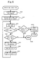
- FIG. 6 is a flowchart showing an e-mail editing process in the host computer 18.
- FIG. 7 is a flowchart showing a stamp type retrieving subroutine in the e-mail editing process of FIG. 6.
- FIG. 9 is a flowchart showing a name retrieving subroutine in the e-mail editing process of FIG. 6.
- FIG. 10 is a flowchart showing an address retrieving subroutine in the e-mail editing process of FIG. 6.
- FIG. 11 is a flowchart showing a buffer laying-out subroutine in the e-mail editing process of FIG. 6.
- FIG. 12 shows an example of a brochure to be supplied previously to customers in this embodiment.
- FIG. 13 shows an example of transmission data displayed on the display of the cellular phone.
- FIG. 14 shows a screen of the e-mail editing program displayed on the display of the host computer 18.
- FIG. 15 shows a difference, in name and address buffer layouts, between the two types of stamp face designs.
- FIG. 16 shows an example of a stamp face layout produced according to this embodiment.
- FIG. 17 is an external perspective view of a stamp produced according to this embodiment.
- step S1 customers 11a-11d operate the operation unit 72 of their respective cellular phones 12a-12d to compose e-mail containing text data for a desired stamp to be produced.
- the e-mail needs to be composed by following a predetermined rule to facilitate editing by the host computer 18.
- the rule may be to enter a plurality of entry items by delimiting each entry item by a predetermined symbol (for example, a semicolon (;)). It is preferable to previously supply the brochure 101, as shown in FIG. 2, to customers to notify them of such an e-mail composing rule.
- the e-mail composed in this embodiment contains three entry items, namely, the stamp type, entry item 1 (for example, a name), and entry item 2 (for example, an address).
- the e-mail composing rule two types of stamp face designs, an exemplary entry of e-mail, a stamp face sample produced based on the e-mail, and a telephone number (or e-mail address) of an e-mail recipient are printed.
- the contents of the composed e-mail are stored in the RAM 63 as code data and displayed, as shown in FIG. 13, on the display 73 of the cellular phone 12a.
- step S2 the customer lla presses an e-mail transmission button of the cellular phone 12a to transmit the e-mail composed in step S1 to the host computer 18.
- the cellular phones 12a-12d must be located within a service area covered by the cellular phone service company.
- a cellular phones is not necessarily required to be located within the service area, and a customer, if having a cellular phone, can compose e-mail for ordering a stamp at anytime and anywhere.
- step S3 the host computer 18 receives the e-mail transmitted from the cellular phones 12a-12d.
- the received e-mail is stored in the RAM 83 of the host computer 18.
- Each piece of e-mail received by the host computer 18 preferably includes, in its header, data representing the e-mail sender's cellular phone number, other than text data representing the stamp type, name, and address entered in step S1.
- the host computer 18, if provided with the cellular phone number of an e-mail sender, is enabled to perform mail management using the cellular phone number unique to each customer and proceed with the subsequent processes smoothly. Also, this prevents a wrong stamp from being delivered later to a customer.
- Customer identifying information such as the cellular phone number may be entered in step S1 by the customer.
- the customer identifying information may be an e-mail address or a previously registered ID number, instead of the cellular phone number.
- step S3 e-mail for acknowledging receipt of e-mail or for notifying of the time of completion of a stamp estimated from the stamp order situations may be returned to the respective cellular phones 12a-12d of the customers 11a-11d. This obviates the need for the customers 11a-11d to wait for the stamp 20 at a delivery place.
- step S4 the e-mail editing program installed in the host computer 18 is started to select an piece of e-mail to be edited from a list of pieces of e-mail received by the host computer 18 (FIG. 14).
- step S5 the piece of e-mail selected in step S4 is processed using the e-mail editing program as described below.
- the e-mail editing process includes five steps, namely, initialization (step S51), retrieval of stamp type (step S52), retrieval of name (step S53), retrieval of address (step S54), and buffer layout (step S55). These steps will be described with reference to FIGS. 7 through 11.
- step S51 a read pointer stored in the RAM 83 of the host computer 18 for indicating an e-mail read point is moved to the head of the piece of e-mail to be edited.
- step S52 the contents of the stamp type buffer in the RAM 83 are cleared in step S520, as shown in FIG. 8. Then in step S521, a stamp type buffer write pointer for indicating a data write point in the stamp type buffer is initialized. Then in step S522, a text code included in code data and located at a point indicated by the read pointer is retrieved from the body of the piece of e-mail. Then it is determined, in step 523, whether the text code is indicative of a delimiting symbol (for example, a semicolon (;)) for an entry item.
- a delimiting symbol for example, a semicolon (;)
- step S524 On the assumption that the stamp type data has already been retrieved.
- step S524 it is determined whether the data retrieved and stored in the stamp type buffer represents the stamp type ("I" or "2" in this embodiment).
- the data stored in the stamp type buffer is determined to represent the stamp type (S524: YES)
- control goes to step S5241 on the assumption that the data representing the stamp type has been correctly retrieved, and the read pointer is incremented by one and this subroutine is completed.
- step S526 where error handling is performed.
- step S525 on the assumption that the stamp type has not yet been retrieved.
- step S525 it is determined whether the text code retrieved in step S522 is a code suffixed on and indicative of the end of the body of the piece of e-mail (or whether retrieval of a text code was failed in step S522).
- step S525 YES
- step S522 When the text code is determined not to be a code indicative of the end of the body of the piece of e-mail, (S525: NO), the text code retrieved in step S522 is written into the stamp type buffer. Then in the step S528, the read pointer is incremented by one and, in step S529, the stamp type buffer write pointer is incremented by one. After that, control returns to step S522. By repeating these steps, the text code representing the stamp type ("1" or "2" in this embodiment) is written into the stamp type buffer in the RAM 83 of the host computer 18.
- step S53 the contents of the name buffer 0 in the RAM 83 are cleared in step S530, as shown in FIG. 9. Then in step S531, a name buffer 0 write pointer for indicating a data write point in the name buffer 0 is initialized. Then in step S532, a text code included in the code data and located at a point indicated by the read pointer is retrieved from the body of the piece of e-mail. Then it is determined, in step 533, whether the text code is indicative of a delimiting symbol (for example, a semicolon (;)) for an entry item.
- a delimiting symbol for example, a semicolon (;)
- step S533 When the text code is determined to be indicative of a delimiting symbol (S533: YES), control goes to step S534 on the assumption that the name data has already been retrieved. In step S534, the read pointer is incremented by one and this subroutine is completed. On the other hand, when the text code is determined not to be indicative of a delimiting symbol (S533: NO), control goes to step S535 on the assumption that the name data has not yet been retrieved. In step S535, it is determined whether the text code retrieved in step S532 is a code suffixed on and indicative of the body of the piece of e-mail (or whether retrieval of a text code was failed in step S532). When the text code is determined to be a code indicative of the end of the body of the piece of e-mail (S535: YES), control goes to step S536, where error handling is performed.
- step S532 When the text code is determined not to be a code indicative of the end of the body of the piece of e-mail (S535: NO), the text code retrieved in step S532 is written into the name buffer 0 in step S537. Then in the step S538, the read pointer is incremented by one and, in step S539, the name buffer 0 write pointer is incremented by one. After that, control returns to step S532. By repeating these steps, text data representing the name desired by the customer to be engraved is written into the name buffer 0 in the RAM 83 of the host computer 18.
- step S54 the contents of the address buffer 0 in the RAM 83 are cleared in step S540, as shown in FIG. 10. Then in step S541, an address buffer 0 write pointer for indicating a data write point in the address buffer 0 is initialized. Then in step S542, a text code at a point indicated by the read pointer is retrieved from the body of the piece of e-mail. Then it is determined, in step 534, whether the text code is a code suffixed on and indicative of the end of the body of the piece of e-mail (or whether retrieval of a text code was failed in step S542). When the text code is determined to be a code indicative of the end of the body of the piece of e-mail (S543: YES), this subroutine is completed on the assumption that the address data has already been retrieved.
- step S543 When the text code is determined not to be a code indicative of the end of the body of the piece of e-mail (S543: NO), the text code retrieved in step S542 is written into the address buffer 0. Then in the step S544, the read printer is incremented by one and, in step S546, the address buffer 0 write pointer is incremented by one. After that, control returns to step S542. By repeating these steps, text data representing the address desired by the customer to be engraved is written into the address buffer 0 in the RAM 83 of the host computer 18.
- step S55 it is determined whether "1" or "2" is written in the stamp type buffer in the RAM 83 of the host computer 18.
- the stamp type is determined to be "1" (S550: YES)
- the name buffer 1 and the address buffer 1 in the RAM 83 are cleared in step S551, and then the contents of the name buffer 0 are written into the name buffer 1 in step S552, and the contents of the address buffer 0 is written into the address buffer 1 in step S553.
- the stamp type is determined to be "2" (S550: NO)
- the name buffer 2 and the address buffer 2 in the RAM 83 are cleared in step S554, and then the contents of the name buffer 0 are written into the name buffer 2 in step S555, and the contents of the address buffer 0 are written into the address buffer 2 in step S556. In this way, the buffers are laid out and the e-mail editing step is completed.
- Two name buffers and two address buffers are used because, in this embodiment, the name and address engraving positions within the stamp face area are different, as shown in FIG. 15, depending on whether the stamp type is "1" or "2".
- the stamp type is "1”
- a cartoon character is engraved near the left end of the stamp face area and the name and the address must be disposed away a certain distance from the left end.
- the stamp type is "2”
- a cartoon character is engraved near the right end of the stamp face area and the name and the address must be disposed away a certain distance from the right end.
- step S6 of FIG. 5 the data edited in step S5 is supplied to the stamp producing device 19. More specifically, the contents of the stamp type buffer, the contents of the name buffer 1 or 2, whichever is updated more recently, and the contents of the address buffer 1 or 2, whichever is updated more recently are transmitted to the stamp producing device 19 as the stamp producing data.
- the stamp producing device 19 receives the stamp producing data from the host computer 18 and stores it in the RAM 93.
- the CPU 91 generates dot matrix data for engraving the stamp face by referring to font data of letters and data of a cartoon character stored in the ROM 92, based on the stamp producing data stored in the RAM 93. Then the CPU 91 stores the generated dot matrix data in the image buffer in the RAM 93. Then the stamp 20 (FIG. 17) having a desired, engraved stamp face as shown in FIG. 16 is produced by the thermal head 26 and the motors 98 driven based on the dot matrix data.
- the stamp 20 is provided to the customer cash on delivery.
- the customer's cellular phone number is checked to avoid the mismatch between the stamp ordered from the customer and the stamp to be delivered.
- the stamp providing system 1 in this embodiment is provided with an automatic delivery device of produced stamps.
- An automatic delivery device ejects, in response to payment by the customer of a prescribed stamp fee and an entry of the customer's cellular phone number, a stamp associated with the entered phone number. Use of such a device can prevent a shop attendant from delivering a wrong stamp to the customer due to a mistake in checking the phone number.
- the customer may go to the installation site of the stamp producing device 19 to get the stamp 20, or may get, at home, the stamp 20 sent by mail or courier.
- the customers 11a-11d want to order the stamp 20 having a desired stamp face, all they have to do is to send desired data using the cellular phones 12a-12d, instead of taking the trouble to go to the installation site of the stamp producing device 19 and enter data to be engraved in the stamp or fill out an order form. Accordingly, the time and trouble taken by the customers 11a-11d to order the stamp 20 can be substantially saved. Also, automatic production of stamps based on the data transmitted from the customers 11a-11d substantially saves the stamp provider the trouble of entering the data filled in the order form and enables the stamp provider to receive orders from distant customers.
- stamp producing data is generated and transmitted using the cellular phones 12a-12d
- the customers 11a-11d can order a stamp conveniently from various locations, at home and away from home, in their spare time.
- stamps can be produced based on personal information, such as the name and the address of the customers 11a-11d.
- the stamp type together with the name and the address are sent by e-mail to the host computer 18, only the name and the address may be sent by e-mail to the host computer 18 and then the stamp type may be designated later when a customer goes to the site where stamp designs are shown.
- Such a method is effective when stamp design samples cannot be printed previously in the brochure 101 in FIG. 12 due to frequent stamp design changes. Previous transmission of all the data necessary for producing a stamp from a cellular phone, as shown in the embodiment, allows a customer to get a stamp with less trouble and waiting time.
- FIG. 18 is a schematic diagram showing a configuration thereof.
- a cellular phone connected to a host computer is used as a data receiver and eliminates the use of a public line and a modem, which are used in the first embodiment.
- a stamp 20 is produced from a thermoplastic porous material by a stamp producing device 19 located distant from a number of customers (only four customers 11a-11d are shown here by way of example), based on stamp producing data transmitted over the air from their respective cellular phones 12a-12d.
- Text data on a stamp desired to be produced is sent from the cellular phones 12a-12d in the form of e-mail to a cellular phone 12e connected to the host computer 18. More specifically, text data sent over the air from the cellular phones 12a, 12b is sent from a base station 13a of each cellular phone service company to the cellular phone 12e located within a territory of the base station 13a. Text data sent over the air from the cellular phone 12c is sent from a base station 13b, via a cellular phone switching station 14a and the base station 13a, to the cellular phone 12e.
- Text data sent over the air from the cellular phone 12d is sent from a base station 13c, via a cellular phone switching station 14b, another cellular phone switching station 14a, and the base station 13a, to the cellular phone 12e (in this embodiment, a cellular phone connection adapter 89, instead of the modem 17, may be connected to the I/O interface 84, as shown in FIG. 4).
- the e-mail received by the cellular phone 12e is stored in its RAM 63 and retrieved into the host computer 18 using an e-mail retrieving program stored in the cellular phone 12e. Then the e-mail is stored in a RAM 83. After that, the stamp 20 is produced according to the same steps as in the first embodiment and provided to a customer.
- a wireless receiver preferably a cellular phone
- the host computer 18 and the stamp producing device 19 can be installed in locations, within the cellular phone service area, where connection with a public line is hardly established. Accordingly, the installation sites of the host computer 18 and the stamp producing device 19 can be selected more freely and the environment for the host computer 18 to receive data can be built at a lower cost.
- FIG. 19 is a schematic block diagram showing a configuration thereof.
- a stamp producing device 19a or 19b located close to and/or distant from a number of customers (only two customers 11a, 11b are shown here by way of example), produces a stamp 20, based on stamp producing data transmitted over the air from cellular phones 12a, 12b, which are portable wireless data receivers/transmitters owned by the respective customers 11a, 11b.
- Stamp producing data sent from the cellular phones 12a, 12b is sent to a host computer 18 in the form of e-mail.
- the text data contains data to be engraved on a stamp material of the stamp 20 as well as stamp production site designating data.
- e-mail is transmitted over the air as digital signals from the cellular phone 12a, which is located within a territory of a base station 13a shared by the host computer 18, the e-mail is received, via the base station 13a, by the cellular phone 15 connected to the host computer 18.
- the e-mail is transmitted over the air as digital signals from the cellular phone 12b, which is located within a territory of a base station 13b not shared by the host computer 18, the e-mail is received by the cellular phone 15 via the base station 13b, a cellular phone switching station 14, and the base station 13a.
- the host computer 18 transfers the received e-mail by the cellular phone 15, based on the contents thereof, to one of a plurality of cellular phones (only two cellular phones 16a, 16b are shown in this embodiment by way of example).
- Stamp producing devices 19a, 19b are connected to the cellular phones 16a, 16b, via output terminals 17a, 17b, respectively.
- the output terminals 17a, 17b edit stamp face data based on the contents of the received e-mail.
- the edited data is sent to the stamp producing device 19a or 19b.
- the stamp producing device 19a or 19b as described below, optically engraves an image on a stamp material based on the data sent from the output terminal 17a or 17b and produces the stamp 20 having a desired stamp face.
- the cellular phones 16a, 16b constitute data receivers, and the output terminals 17a, 17b and the stamp producing devices 19a, 19b constitute output producing devices.
- FIG. 20 is a block diagram showing a control system of the stamp providing system 3.
- FIG. 20 only each one (cellular phone 12a, output terminal 17a, and stamp producing device 19a) of a number of cellular phones, output terminals, and stamp producing devices usable in the stamp providing system 3 according to this embodiment is representatively shown. Base stations and switching stations are omitted from the figure. Elements structurally similar to those in the first embodiment have the same reference numbers and a detailed description thereof will be omitted.
- the cellular phone 12a has a CPU 61, a ROM 62, a RAM 63, a DSP (digital signal processor) 64, a wireless unit controller 65, and an I/O interface 66, and these devices are connected to each other using a bus 67.
- the output terminal 17a has a CPU 81, a ROM 82, a RAM 83 and an I/O interface 84, and these devises are connected to each other using a bus 85.
- a hard disk 86 Connected to the I/O interface 84 are a hard disk 86, a keyboard 87, a display 88, and a cellular phone connection adapter 89.
- the cellular phone 16a is connected to the cellular phone connection adapter 89 so as to enable data reception/transmission by/from the output terminal 17a via the base station 13a.
- the hard disk 86 magnetically stores a program for loading e-mail from the cellular phone 16a and a program for editing e-mail received and loaded from the cellular phone 16a, a program for exchanging data with the stamp producing device 19a, and other programs.
- the RAM 83 temporarily stores programs read from the hard disk 86, received e-mail, and data entered from the keyboard 87.
- the RAM 83 is provided with name buffers 0-2, address buffers 0-2, a stamp type buffer, a delivery point buffer, and a memory area for various pointers.
- the host computer 18 stores, in addition to an e-mail loading program, a program for unloading e-mail to the cellular phone 15 for e-mail transmission therefrom, and also stores, as will be described later, an e-mail transfer program, instead of the e-mail editing program.
- the stamp producing device 19a is provided with a CPU 91, a ROM 92, a RAM 93, and an I/O interface 94, and these devices are connected to each other using a bus 95.
- the I/O interface 94 is connected to the I/O interface 84 of the output terminal 17a via a cable or the like. This allows the stamp producing device 19a to retrieve stamp face data edited according to this embodiment from the output terminal 17a.
- the ROM 92 stores a control program for controlling the entire operation of the stamp producing device 19a.
- the RAM 93 stores stamp producing data provided from the output terminal 17a.
- the RAM 93 is provided with an image buffer for storing dot matrix data generated based on the stamp producing data.
- FIG. 21 is a main flowchart showing a stamp providing steps according to the third embodiment.
- FIG. 22 is a flowchart showing an e-mail transfer process in the host computer 18.
- FIG. 23 is a flowchart showing an initialization subroutine in the e-mail transfer process of FIG. 22.
- FIG. 24 is a flowchart showing a delivery point retrieving subroutine in the e-mail transfer process of FIG. 22.
- FIG. 25 is a flowchart showing an e-mail transfer subroutine in the e-mail transfer process of FIG. 22.
- FIG. 26 is a flowchart showing an e-mail editing process in the output terminals 17a, 17b.
- FIG. 27 is a flowchart of an initialization subroutine in the e-mail editing process of FIG. 26.
- FIG. 28 is a flowchart of a stamp type retrieving subroutine in the e-mail editing process of FIG. 26.
- FIG. 29 is a flowchart of a name retrieving subroutine in the e-mail editing process of FIG. 26.
- FIG. 30 is a flowchart of an address retrieving subroutine in the e-mail editing process of FIG. 26.
- FIG. 31 is a flowchart of a delivery point retrieving subroutine in the e-mail editing process of FIG. 26.
- FIG. 32 is a flowchart of a buffer laying-out subroutine in the e-mail editing process of FIG. 26.
- FIG. 33 shows a screen of an e-mail editing program displayed on the display of the output terminal 17a or 17b.
- step S101 customers 11a, 11b operate the operation unit 72 of their respective cellular phones 12a, 12b to compose e-mail containing text data on a stamp desired to be produced.
- E-mail is composed, in the same manner as in the first embodiment, by following a predetermined rule, that is, by delimiting each entry item by a semicolon.
- the customers 11a, 11b can select a delivery point of the stamp 20 produced.
- the e-mail composed in this embodiment contains four entry items, namely, the stamp type, entry item 1 (for example, a name), entry item 2 (for example, an address), and the stamp delivery point.
- step S102 the customer lla presses an e-mail transmission button of the cellular phone 12a to transmit the e-mail composed in step S101 to the cellular phone 15.
- step S103 the cellular phone 15 receives the e-mail transmitted from the cellular phones 12a, 12b.
- the e-mail received by the cellular phone 15 is loaded into the host computer 18 using the e-mail loading program.
- the loaded e-mail is stored in the RAM of the host computer 18.
- Each piece of e-mail received by the host computer 18 preferably includes, in its header, data representing the e-mail sender's cellular phone number, other than text data representing the stamp type, name, address, and delivery point entered in step S101.
- step S103 e-mail for acknowledging receipt of e-mail or for notifying of the time of completion of a stamp estimated from the order situations may be returned to the respective cellular phones 12a, 12b of the customers 11a, 11b. This obviates the need for the customers 11a, 11b to wait for the stamp 20 at a delivery place.
- step S104 the e-mail loaded into the host computer 18 in step S103 is transferred, as described below, to either of the cellular phones 16a or 16b connected to the output terminals 17a, 17b, respectively, using the e-mail transfer program and the e-mail unloading program.
- the e-mail transfer process includes three steps, namely, initialization (step S41), retrieval of delivery point (step S42), and e-mail transfer to delivery point (step S43). These steps will be described with reference to FIGS. 23 through 25.
- step S41 a read pointer stored in the RAM of the host computer 18 for indicating an e-mail read point is moved to the end of the body of a piece of e-mail to be edited.
- step S42 the contents of the delivery point buffer in the RAM are cleared, as shown in FIG. 24. Then in step S421, a delivery point buffer write pointer that indicates a data write point in the delivery point buffer is initialized. Then in step S422, a text code at a point indicated by the read pointer is retrieved from the body of the piece of e-mail. Then it is determined, in step S423, whether the text code is indicative of a delimiting symbol (for example, a semicolon (;)) for an entry item.
- a delimiting symbol for example, a semicolon (;)
- step S429 When the text code is indicative of a delimiting symbol (S423: YES), control goes to step S429 on the assumption that the delivery point data has already been retrieved.
- step S429 it is determined whether the data retrieved and stored in the delivery point buffer is data representing the delivery point ("1" or "2" in this embodiment). As a result, when the data stored in the delivery point buffer is the data representing the delivery point (S429: YES), this subroutine is completed on the assumption that the data representing the delivery point has been correctly retrieved.
- step S425 When the data stored in the delivery point buffer is not the data representing the delivery point (S429: NO), control goes to step S425, where error handling is performed.
- step S424 it is determined whether the read pointer is at the head of the piece of e-mail.
- S424 YES
- control goes to step S425, where error handling is performed.
- step S422 When the read pointer is determined not to be at the head of the piece of e-mail (S424: NO), the text code retrieved in step S422 is written into the delivery point buffer in step S426. Then in the step S427, the read pointer is decremented by one and, in step S428, the delivery point buffer write pointer is decremented by one. After that, control returns to step S422. By repeating these steps, the text code representing the delivery point ("1" or "2" in this embodiment) is written into the delivery point buffer in the RAM of the host computer 18.
- step S43 it is determined, in step S430, whether "1" is contained in the delivery point buffer in the RAM.
- step S430 determines whether "1" is contained in the delivery point buffer in the RAM.
- step S431 the host computer 18 transmits data to the cellular phone 15, using the e-mail unloading program, in order to transfer a received piece of e-mail to the destined cellular phone 16a (at the "exit” in this embodiment) associated with the delivery point "1".
- the data is transmitted as a piece of e-mail destined for the cellular phone 16a and has the same body as the body of the data transmitted from the cellular phone 12a or 12b.
- step S432 When "2" is contained in the delivery point buffer (S430: NO), control goes to step S432, where the host computer 18 transmits data to the cellular phone 15, using the e-mail unloading program, in order to transfer a received piece of e-mail to the destined cellular phone 16b (in "front of Ferris wheel” in this embodiment) associated with the delivery point "2".
- the data is transmitted as a piece of e-mail destined for the cellular phone 16b and has the same body as the body of the data transmitted from the cellular phone 12a or 12b.
- step S105 the cellular phone 15 transmits the piece of e-mail received from the host computer 18 to the designated cellular phone 16a or 16b, via the base station 13a, (the switching station 14, and the base station 13b).
- step S106 the cellular phone 16a or 16b receives the transferred piece of e-mail and stores it in its RAM 63.
- step S107 the output terminal 17a or 17b loads, using the e-mail loading program installed therein, the piece of e-mail from the cellular phone 16a or 16b and stores it in its RAM 83.
- step S108 the e-mail editing program is started to select a piece of e-mail to be edited from a list of pieces of e-mail (FIG. 33) stored in the RAM 83 of the output terminal 17a or 17b.
- the selected piece of e-mail is processed using the e-mail editing program as described below.
- the e-mail editing process includes six steps, namely, initialization (step S81), retrieval of stamp type (step S82), retrieval of name (step S83), retrieval of address (step S84), retrieval of delivery point (step S85), and buffer layout (step S86). These steps will be described with reference to FIGS. 27 through 32.
- step S81 a read pointer stored in the RAM 83 of the output terminal 17a or 17b for indicating an e-mail read point is moved to the head of the body of the piece of e-mail to be edited.
- step S82 the contents of the stamp type buffer in the RAM 83 are cleared in step S820, as shown in FIG. 28. Then in step S821, a stamp type buffer write pointer for indicating a data write point in the stamp type buffer is initialized. Then in step S822, a text code at a point indicated by the read pointer is retrieved from the body of the piece of e-mail. Then it is determined, in step 823, whether the text code is indicative of a delimiting symbol (for example, a semicolon (;)) for an entry item.
- a delimiting symbol for example, a semicolon (;)
- step S824 it is determined whether the data retrieved and stored in the stamp type buffer is data representing the stamp type ("1" or "2" in this embodiment). As a result, when the data stored in the stamp type buffer is the data representing the stamp type (S824: YES), control goes to step S8241 on the assumption that the data representing the stamp type has been correctly retrieved, and the read pointer is incremented by one and this subroutine is completed.
- step S826 where error handling is performed.
- step S823 when the text code is not indicative of a delimiting symbol (S823: NO), control goes to step S825 on the assumption that the stamp type has not yet been retrieved.
- step S825 it is determined whether the text code retrieved in step S822 is a code suffixed on and indicative of the end of the body of the piece of e-mail (or whether retrieval of a text code was failed in step S822).
- the text code is determined to be a code indicative of the end of the body of the piece of e-mail (S825: YES)
- control goes to step S826, where error handling is performed.
- step S822 When the text code is determined not to be a code indicative of the end of the body of the piece of e-mail, (S825: NO), the text code retrieved in step S822 is written into the stamp type buffer. Then in the step S828, the read pointer is incremented by one and, in step S829, the stamp type buffer write pointer is incremented by one. After that, control returns to step S822. By repeating these steps, the text code representing the stamp type ("1" or "2" in this embodiment) is written into the stamp type buffer in the RAM 83 of the output terminal 17a or 17b.
- step S83 the contents of the name buffer 0 in the RAM 83 are cleared in step S830, as shown in FIG. 29. Then in step S831, a name buffer 0 write pointer for indicating a data write point in the name buffer 0 is initialized. Then in step S832, a text code at a point indicated by the read pointer is retrieved from the body of the piece of e-mail. Then it is determined, in step 833, whether the text code is indicative of a delimiting symbol (for example, a semicolon (;)) for an entry item.
- a delimiting symbol for example, a semicolon (;)
- step S834 When the text code is determined to be indicative of a delimiting symbol (S833: YES), control goes to step S834 on the assumption that the name data has already been retrieved. In step S834, the read pointer is incremented by one and this subroutine is completed. On the other hand, when the text code is determined not to be indicative of a delimiting symbol (S833: NO), control goes to step S835 on the assumption that the name data has not yet been retrieved. In step S835, it is determined whether the text code retrieved in step S832 is a code suffixed on and indicative of the end of the body of the piece of e-mail (or whether retrieval of a text code was failed in step S832). When the text code is determined to be a code indicative of the end of the body of the piece of e-mail (S835: YES), control goes to step S836, where error handling is performed.
- step S832 When the text code is determined not to be a code indicative of the end of the body of the piece of e-mail (S835: NO), the text code retrieved in step S832 is written into the name buffer 0. Then in the step S838, the read pointer is incremented by one and, in step S839, the name buffer 0 write pointer is incremented by one. After that, control returns to step S832. By repeating these steps, text data representing the name desired by the customer to be engraved is written into the name buffer 0 in the RAM 83 of the output terminal 17a or 17b.
- step S84 the contents of the address buffer 0 in the RAM 83 are cleared in step S840, as shown in FIG. 30. Then in step S841, an address buffer 0 write pointer for indicating a data write point in the address buffer 0 is initialized. Then in step S842, a text code at a point indicated by the read pointer is retrieved from the body of the piece of e-mail. Then it is determined, in step 843, whether the text code is indicative of a delimiting symbol (for example, a semicolon (;)) for an entry item.
- a delimiting symbol for example, a semicolon (;)
- step S844 When the text code is determined to be indicative of a delimiting symbol (S843: YES), control goes to step S844 on the assumption that the address data has already been retrieved. In step S844, the read pointer is incremented by one and this subroutine is completed. When the text code is determined not to be indicative of a delimiting symbol (S843: NO), control goes to step S845 on the assumption that the address data has not yet been retrieved.
- step S845 it is determined whether the text code is suffixed on and indicative of the end of the body of the piece of e-mail (or whether retrieval of a text code was failed in step S842).
- the text code is determined to be a code indicative of the end of the body of the piece of e-mail (S845: YES)
- control goes to step S846, where error handling is performed.
- step S842 When the text code is determined not to be a code indicative of the end of the body of the piece of e-mail (S845: NO), the text code retrieved in step S842 is written into the address buffer 0 in step S847. Then in the step S848, the read pointer is incremented by one and, in step S849, the address buffer 0 write pointer is incremented by one. After that, control returns to step S842. By repeating these steps, text data representing the address desired by the customer to be engraved is written into the address buffer 0 in the RAM 83 of the output terminal 17a or 17b.
- step S85 the contents of the delivery point buffer in the RAM 83 are cleared in step S850, as shown in FIG. 31. Then in step S851, a delivery point write pointer for indicating a data write point in the delivery point buffer is initialized. Then in step S852, a text code at a point indicated by the read pointer is retrieved from the body of the piece of e-mail.
- step S858 it is determined whether the text code is a code suffixed on and indicative of the end of the body of the piece of e-mail (or whether retrieval of a text code was failed in step S852).
- the text code is determined to be a code indicative of the end of the body of the piece of e-mail (S853: YES)
- this subroutine is completed on the assumption that the delivery point data has already been retrieved.
- step S853 When the text code is determined not to be a code indicative of the end of the body of the piece of e-mail (S853: NO), the text code retrieved in step S852 is written into the delivery point buffer in step S854. Then in the step S855, the read pointer is incremented by one and, in step S856, the delivery point buffer write pointer is incremented by one. After that, control returns to step S852. By repeating these steps, text data representing the delivery point desired by the customer is written into the delivery point buffer in the RAM 83 of the output terminal 17a or 17b.
- step S86 it is determined whether "1" or "2" is written into the stamp type buffer in the RAM 83 of the output terminal 17a or 17b.
- the stamp type is "1" (S860: YES)
- the name buffer 1 and the address buffer 1 in the RAM 83 are cleared in step S861.
- the contents of the name buffer 0 are written into the name buffer 1 in step S862, and the contents of the address buffer 0 is written into the address buffer 1 in step S863.
- the stamp type is "2" (S860: NO)
- the name buffer 2 and the address buffer 2 in the RAM 83 are cleared in step S864.
- the delivery point data is contained in each piece of e-mail transmitted from the host computer 18.
- the delivery point data is retrieved into the output terminal 17a or 17b in step S85.
- Step S85 is not necessarily required but allows the output terminal 17a or 17b to confirm the stamp delivery point.
- step S109 of FIG. 21 control goes back to step S109 of FIG. 21, where, from among the data edited in step S108, the contents of the stamp type buffer, the contents of the name buffer 1 or 2, whichever is updated more recently, and the contents of the address buffer 1 or 2, whichever is updated more recently are transmitted to the stamp producing device 19a or 19b as the stamp producing data.
- the stamp producing device 19a or 19b receives the stamp producing data from the output terminal 17a or 17b and stores it in the RAM 93.
- the CPU 91 generates dot matrix data for engraving the stamp face by referring to font data of letters and data of a cartoon character stored in the ROM 92, based on the stamp producing data stored in the RAM 93, and stores the generated dot matrix data in an image buffer in the RAM 93.
- the stamp 20 (FIG. 17) having a desired engraved stamp face as shown in FIG. 16 is produced by the thermal head 26 and the motors 98 driven based on the dot matrix data.
- step S110 the stamp 20 is provided to the customer cash on delivery.
- the customers 11a, 11b can select a more convenient location as a stamp delivery point from the two locations, and get the stamp 20 at a location relatively near the customers 11a, 11b without the trouble of going to a distant delivery point.
- orders from the customers 11a, 11b are centralized in the host computer 18. This allows the customers 11a, 11b to just send data to the single host computer 18, without the trouble of selecting one of the output terminals 17a, 17b as a destination of data transmission, which will be a delivery point. As a result, erroneously destined data transmission is prevented. Also, order management can be performed only by the host computer 18.
- stamp producing data is generated and transmitted using the cellular phones 12a, 12b
- the customers 11a, 11b can order a stamp conveniently from various locations, at home and away from home, in their spare time.
- a wireless receiver (preferably a cellular phone) is connected to each of the host computer 18 and the output terminals 17a, 17b.
- a wireless receiver preferably a cellular phone
- Such a configuration allows the host computer 18 and the output terminals 17a, 17b to be installed in locations, within the cellular phone service area, where connection with a public line is hardly established. Accordingly, the installation sites of these devices can be selected more freely and the environment for the host computer 18 and the output terminals 17a, 17b to receive data can be built at a lower cost.
- FIG. 34 is a schematic diagram showing a configuration thereof.
- a stamp producing device 19 located within a relatively short range from a number of customers (only four consumers 11a-11d are shown here by way of example) produces a stamp 20, based on stamp producing data transmitted over the air using a wireless short-range data transmission technique (such as Bluetooth) from cellular phones 12a-12d, which are portable wireless data receivers/transmitters owned by the respective consumers 11a-11d.
- a wireless short-range data transmission technique such as Bluetooth
- the cellular phones 12a-12d used in this embodiment have, aside from a function of receiving/transmitting voice by converting it to digital (or analog) signals, a function of receiving/transmitting textual information by converting it to code data from/to other computers and cellular phones that adopt the same wireless short-range data transmission technique.
- Code data sent from the cellular phones 12a-12d is sent to a host computer 18 connected to the stamp producing device 19.
- the code data contains text data to be engraved on a stamp material of the stamp 20.
- the data containing textual information and sent from the cellular phones 12a-12d as digital signals is directly received by the host computer 18, which adopts the same wireless short-range data transmission technique as that adopted by the cellular phones 12a-12d.
- a wireless short-range data communication technique is adopted as a data communication interface between the cellular phones 12a-12d and the host computer 18.
- This allows only cellular phones located within a relatively short range from the host computer 18 to communicate with the host computer 18.
- Bluetooth using a career frequency band of 2.4 GHz is adopted as the wireless short-range data communication technique
- only cellular phones located within approximately 10 m from the host computer 18 can communicate with the host computer 18.
- the cellular phones 12a, 12b, 12c can transmit data to the host computer 18, but the cellular phone 12d cannot do so.
- the adoption of Bluetooth advantageously enables high-speed data transmission between cellular phones and the host computer 18 at approximately 1M bit/second even when there is an obstruction therebetween.
- the host computer 18 and the stamp producing device 19 constitute an output producing device.
- FIG. 35 is a block diagram showing a control system of the stamp providing system 4.
- FIG. 35 only one (cellular phone 12a) of a number of cellular phones usable in the stamp providing system 4 according to the fourth embodiment is representatively shown. Elements structurally similar to those in the first embodiment have the same reference numbers and a detailed description thereof will be omitted.
- the constituents of each part in the fourth embodiment are similar to those in the first embodiment, and a detailed description thereof is omitted.
- the cellular phone 12a in this embodiment differs from the first embodiment in that its wireless unit 70 is structured in conformity with the short-range wireless data transmission standards, such as Bluetooth, and transmits over the air desired voice data and text data, as digital signals, from an antenna 71 to an antenna 78 of the host computer 18. Conversely, the wireless unit 70 is also used to directly receive data transmitted from the host computer 18 via the antenna 71.
- the short-range wireless data transmission standards such as Bluetooth
- the wireless unit 77 of the host computer 18 in this embodiment is also structured in conformity with the short-range wireless data transmission standards, such as Bluetooth.
- the wireless unit 77 receives data transmitted from the cellular phones 12a-12d via the antenna 78.
- the wireless unit 77 is also used to transmit over the air desired voice data and text data, as digital signals, from the antenna 78 to the cellular phones 12a-12d.
- stamp providing steps in the stamp providing system 4 according to the embodiment will be described.
- the steps identified by the same names as in the first embodiment involve the same processes as in the first embodiment, and thus a detailed description of the internal processes will be omitted.
- step 201 the customers 11a-11d operate the operation unit 72 of their respective cellular phones 12a-12d to create a data file including text data for a desired stamp to be produced.
- step S202 the consumer lla presses a data transmission button of the cellular phone 12a to transmit the data file created in step S201 to the host computer 18.
- step S203: YES when the cellular phones 12a-12d are located within a predetermined range from the host computer 18 (within approximately 10 m in the case of Bluetooth)(step S203: YES), control goes to step S204. On the other hand when the cellular phones 12a-12d are not located within the predetermined range from the host computer 18 (step S203: NO), control returns to S202.
- step S201 creation of a data file in step S201, however, cellular phones are not necessarily required to be located within the predetermined range from the host computer 18, and consumers, if they have a cellular phone, can create a data file for ordering a desired stamp at anytime and anywhere.
- step S204 the host computer 18 directly receives the data file transmitted from the cellular phones 12a-12d.
- the received data file is stored in the RAM 83 of the host computer 18.
- step S205 the host computer 18 starts a data editing program installed therein and selects a data file to edit from a list of received data files. Then in step S206, the host computer 18 edits the data file selected in step S205, using the data editing program.
- step S207 the data edited in step S206 is supplied to the stamp producing device 19.
- the stamp producing device 19 receives the stamp producing data from the host computer 18 and stores it in the RAM 93.
- the CPU 91 generates dot matrix data for engraving the stamp face by referring to font data of letters and data of a cartoon character stored in the ROM 92, based on the stamp producing data stored in the RAM 93, and stores the dot matrix data in an image buffer in the RAM 93.
- the stamp 20 (FIG. 17) having a desired engraved stamp face as shown in FIG. 16 is produced by the thermal head 26 and the motors 98 driven based on the dot matrix data.
- step S208 the stamp 20 is delivered to the customer 11a cash on delivery.
- the range that permits communication between the cellular phones 12a-12d and the host computer 18 is limited to a relatively short range, operators (consumers) of the cellular phones 12a-12d must actually go to a location close to the host computer 18 to order the stamp 20.
- customers cannot get the specially designed stamp 20 produced by the stamp producing device 19 without going to a location close to the host computer 18.
- the host computer 18 can receive orders only from customers situated within an extremely narrow range. Accordingly, value can be added to the stamp 20 produced by the stamp producing device 19.
- the fourth embodiment is suitable for use in an amusement facility.
- the host computer 18 and the stamp producing device 19 is installed in each pavilion of an amusement facility so that a different stamp (or content) is produced in each pavilion. It is expected that customers make a stop at all pavilions to gather all types of stamps.
- the data transmitted from the cellular phones 12a-12d bypasses a base station and a public line and is directly received by the host computer 18.
- the host computer 18 there is no need to pay communication fees to a cellular phone service company and a public line company, and the cost of communication between the cellular phones 12a-12d and the host computer 18 can be significantly reduced.
- a stamp providing system can be configured.
- CDs compact discs
- voice data recorder or stickers/labels with an image printed thereon can be provided using a device for producing a sticker/label upon receipt of image data.
- the electronic mailing system where e-mail is automatically sent to the host computer 18 is described by way of example, another electronic mailing system can be used, where e-mail is stored in an e-mail server separate from the host computer 18 and is received by the host computer 18 by access to the e-mail server. Also, in the above-described embodiments, the number of entry items and the types of the stamp designs can be arbitrarily changed.
- a device used by a customer to transmit e-mail is not limited to a cellular phone, and any device can be used if it is capable of wireless transmission.
- e-mail may be transmitted using a mobile computer or a PDA (Personal Digital Assistant).
- PDA Personal Digital Assistant
- infrared wireless communication in conformity with IrDA (Infrared Data Association) standards may be used.
- the data receiver and the output producing device are disposed in a pair (or adjacent to each other), the data receiver and the output producing device may be disposed distant from each other if data transmission can be accomplished therebetween by wired communication or long-range wireless communication.
- an output can be produced at a designated delivery point as in the third embodiment.
- data transmission from the host computer 18 to each customer is performed by short-range wireless communication (Bluetooth)
- data transmission from the host computer 18 may be performed by long-range communication.
- acknowledgement of receipt of an order from a customer and notification of completion of an output are reliably made by long-range communication.
Abstract
Description
- The present invention relates to a system and method for providing a tangible output, such as a stamp and a name card, in response to a request from a customer.
- In recent years, amusement facilities, such as a game arcade and an amusement park, are often provided with a name card producing device that produces a name card on which personal information including a customer's name and address is printed, a stamp producing device that produces a stamp by engraving an image on a stamp material based on personal information, and a sticker producing device that produces a peel-off sticker based on image data obtained by taking a picture of a customer's face. Such devices are increasingly popular because, in many of such devices, an original cartoon character of the amusement park or a commonly popular cartoon character can be printed or engraved together with the personal information, and because a name card and a stamp are provided in a short time and at low cost.
- Under present circumstances, when a customer uses the above-described card or stamp producing device, the customer must go to a site where a desired device is installed and operate the device to enter data, or fill out a predetermined order form and submit it to an administrator of the device.
- However, going to the installation site of a desired device is troublesome for the customer. In addition, it is relatively time-consuming to enter data into the desired device or fill out an order form. When many customers queue up for the desired device, they must wait for their own turn. Thus, a drawback of such a device is that it takes a very long time to get a desired name card or the like. Another drawback of such a system is that when the customer fills out an order form, the device manager must take the trouble to enter data based on the items entered in the order form.
- Accordingly, it is an object of the invention to provide an output providing system and method that enables a customer to order a tangible output, such as a name card or a stamp, at less expense in time and trouble and that can also save an output provider time and trouble.
- According to the invention, the time and trouble taken by a customer when ordering an output can be substantially saved. In addition, an output provider can produce an output based on the data transmitted from a customer. This will substantially save the output provider the trouble of entering data and also enable the output provider to receive massive orders from a great number of customers without any confusion. Furthermore, output-related data is generated and transmitted using a wireless data transmitter. Thus, a customer can order a stamp conveniently from various locations, at home and away from home, in his/her spare time.
- To achieve the above-described object, an output providing system includes an electronic mail (hereinafter referred to as e-mail) receiver that can receive pieces of e-mail from customers, by wireless communication, each piece of e-mail containing data on a requested output along with customer information; an e-mail returning device that returns, upon receipt of each piece of e-mail by the e-mail receiver, a piece of e-mail for acknowledging receipt of each request to each of the customers, based on the customer information; a data analyzer that analyzes contents of each piece of e-mail received by the e-mail receiver and converts the data on the requested output to image data to be outputted on an output medium; an output producing device that receives the image data and outputs an image on the output medium; and an e-mail transmitter that transmits a piece of e-mail for notifying each of the customers of completion of production of the requested output by the output producing device.
- The invention will be described in detail with reference to preferred embodiments thereof and the accompanying drawings wherein:
- FIG. 1 is a schematic diagram showing a configuration of a stamp providing system according to a first embodiment of the invention;
- FIG. 2 is a general perspective view of a stamp producing device shown in FIG. 1;
- FIG. 3 is a general cross-sectional view of the stamp producing device shown in FIG. 1;
- FIG. 4 is a block diagram showing a control system of the stamp providing system according to the first embodiment of the invention;
- FIG. 5 is a main flowchart showing stamp providing steps in the first embodiment of the invention;
- FIG. 6 is a flowchart showing an e-mail editing process in FIG. 5 executed by a host computer;
- FIG. 7 is a flowchart of an initialization subroutine in the e-mail editing process of FIG. 6;
- FIG. 8 is a flowchart of a stamp type retrieving subroutine in the e-mail editing process of FIG. 6;
- FIG. 9 is a flowchart of a name retrieving subroutine in the e-mail editing process of FIG. 6;
- FIG. 10 is a flowchart of an address retrieving subroutine in the e-mail editing process of FIG. 6;
- FIG. 11 is a flowchart of a buffer laying-out subroutine in the e-mail editing process of FIG. 6;
- FIG. 12 shows an example of a brochure to be previously supplied to customers in the first embodiment of the invention;
- FIG. 13 shows an example of transmission data displayed on a display of a cellular phone;
- FIG. 14 shows a screen of an e-mail editing program displayed on a display of the host computer in the first embodiment;
- FIG. 15 shows a difference, in name and address buffer layouts, between two types of stamp face designs;
- FIG. 16 shows an example of a stamp face layout produced according to an embodiment of the invention;
- FIG. 17 is an external perspective view of a stamp produced according to an embodiment of the invention;
- FIG. 18 is a schematic diagram showing a configuration of a stamp providing system according to a second embodiment of the invention;
- FIG. 19 is a schematic diagram showing a configuration of a stamp providing system according to a third embodiment of the invention;
- FIG. 20 is a block diagram showing a control system of the stamp providing system according to the third embodiment of the invention;
- FIG. 21 is a main flowchart showing stamp providing steps in the third embodiment of the invention;
- FIG. 22 is a flowchart showing an e-mail transfer process in FIG. 21 executed by a host computer;
- FIG. 23 is a flowchart showing an initialization subroutine in the e-mail transfer process of FIG. 22;
- FIG. 24 is a flowchart showing a delivery point retrieving subroutine in the e-mail transfer process of FIG. 22;
- FIG. 25 is a flowchart showing an e-mail transfer subroutine in the e-mail transfer process of FIG. 22;
- FIG. 26 is a flowchart showing an e-mail editing process in FIG. 21 executed by an output terminal;
- FIG. 27 is a flowchart of an initialization subroutine in the e-mail editing process of FIG. 26;
- FIG. 28 is a flowchart of a stamp type retrieving subroutine in the e-mail editing process of FIG. 26;
- FIG. 29 is a flowchart of a name retrieving subroutine in the e-mail editing process of FIG. 26;
- FIG. 30 is a flowchart of an address retrieving subroutine in the e-mail editing process of FIG. 26;
- FIG. 31 is a flowchart of a delivery point retrieving subroutine in the e-mail editing process of FIG. 26;
- FIG. 32 is a flowchart of a buffer laying-out subroutine in the e-mail editing process of FIG. 26;
- FIG. 33 shows a screen of an e-mail editing program displayed on a display of the host computer in the third embodiment;
- FIG. 34 is a schematic diagram showing a configuration of a stamp providing system according to a fourth embodiment of the invention;
- FIG. 35 is a block diagram showing a control system of the stamp providing system according to the fourth embodiment of the invention; and
- FIG. 36 is a main flowchart showing stamp providing steps in the fourth embodiment of the invention.
-
- Preferred embodiments of the invention will be described with reference to the accompanying drawings.
- According to a first embodiment of the invention, a stamp providing system is provided which produces a stamp from a thermoplastic porous material in response to a request from a customer. Referring now to FIG. 1, a general configuration of the stamp providing system according to the first embodiment will be described. FIG. 1 is a schematic block diagram of the stamp providing system according to the first embodiment.
- In the
stamp providing system 1 shown in FIG. 1, astamp producing device 19 located distant from a number of customers (only fourcustomers 11a-11d are shown here by way of example) produces astamp 20, based on stamp producing data transmitted over the air fromcellular phones 12a-12d, which are portable wireless data receivers/transmitters owned by therespective customers 11a-11d. Thecellular phones 12a-12d used in this embodiment have, aside from a function of receiving/transmitting voice by converting it to digital (or analog) signals, a function of receiving/transmitting textual information by converting it to code data from/to other computers and cellular phones (for example, a message receiving/transmitting function and an e-mail receiving/transmitting function using the Internet, which are provided by each cellular phone company). - Stamp producing data sent from the
cellular phones 12a-12d is sent to ahost computer 18 connected to thestamp producing device 19 in the form of e-mail. The text data contains, as will be described later, data to be engraved on a stamp material of thestamp 20. The e-mail containing textual information and sent from thecellular phones 12a-12d as digital signals is sent from abase station 13 of each cellular phone service company to a publicline switching station 15, via a cellularphone switching station 14. The e-mail is converted into analog signals at any one of these stations and sent, via a public line, to amodem 17 connected to thehost computer 18. Then the e-mail is coveted from analog to digital signals and is received by thehost computer 18. - The
host computer 18, as will be described in detail later, edits stamp face data for producing a stamp, based on the contents of the received e-mail. The edited data is sent to thestamp producing device 19. Thestamp producing device 19 optically engraves an image on a stamp material based on the data sent from thehost computer 18 and produces thestamp 20 having a desired stamp face. - In the first embodiment, the
host computer 18 constitutes a data receiver, and thehost computer 18 and thestamp producing device 19 constitute an output producing device. - Referring now to FIGS. 2 and 3, the structure of the
stamp producing device 19 will be described. FIG. 2 is a general perspective view of thestamp producing device 19 shown in FIG. 1, and FIG. 3 is a general cross-sectional view thereof. Thestamp producing device 19 has afilm magazine 24 removable from a devisebody 22 and storing a plurality of transparentoriginal films 23, asupply port 25 disposed near thefilm magazine 24 for supplying cut sheets CS for stamp ID labels, aprint unit 27 provided with aprinthead 26, astamp unit 29 for forming a stamp face, based on a printedoriginal film 23, on a stamp material (not shown) disposed at a lower surface of thestamp body 28, astamp storage 30 for storing thestamp body 28 during stamp face forming, and adischarge port 31 disposed near thestamp unit 29 in thedevice body 2 for discharging the cut sheets CS and theoriginal films 23. - A
head holder unit 32, provided on an upper surface of theprint unit 27, has at its lower side athermal head 26 and is upwardly pivotable about ashaft 33, thereby allowing maintenance of the inside of the device. A leading edge of the uppermostoriginal film 23 on thefilm magazine 24 is pressed into contact with asupply roller 34. When thesupply roller 34 is rotated in this state, theoriginal film 23 is properly fed to theprint unit 27. The cut sheet CS is fed to a position printable by thethermal head 26 by a pair offeed rollers supply port 25, asheet guide 37 provided immediately behind thesupply port 25 so as to be bent toward thethermal head 26, and aguide rail 38. - The
print unit 27 is provided with a supply roll 40 and a take-up roll 40b ofthermal transfer ribbon 39 covered with wax base ink. Aplaten 42 is provided below thethermal head 26 disposed at the lower side of thehead holder unit 32. Provided below thesupply roll 40a are theguide rail 38 for guiding theoriginal film 23 and the cut sheet CS to a space between thethermal head 26 and theplaten 42, and apresser guide 43 for preventing theoriginal film 23 and the cut sheet CS from floating while being fed. In addition, provided downstream of thethermal head 26 are atransport guide 44 and a pair ofsupply rollers 45. - A light-emitting unit (HU) 49 provided with a
xenon tube 48 enclosed by areflector box 47 is removably provided below thestamp unit 29. The light-emittingunit 49 with astage 50 for holding thereon thestamp body 28 is removable from thestamp producing device 19 by upwardly sliding aslide lever 51. Thestamp unit 29 is also provided with atop cover 52 and a fronttop cover 53, which are opened/closed for replacement of thestamp body 28. - The
stamp producing device 19 is connected to thehost computer 18 via a cable and executes, under the control of thehost computer 18, various operations, such as printing a positive image on theoriginal film 23, printing an ID label on the cut sheet CS, and engraving an image on a stamp material based on theoriginal film 23 with a positive image printed thereon. - More specifically, the
thermal head 26 prints a positive image composed of predetermined letters or the like on theoriginal film 23, which has been fed from thefilm magazine 24 to theprint unit 27, and the printedoriginal film 23 is fed to thestamp unit 29. Then the light-emittingunit 49 irradiates the stamp material disposed under thestamp body 28 with light through theoriginal film 23 to engrave the image on the stamp material. In this way, a series of stamp producing operations by thestamp producing device 19 is completed. - For printing on the cut sheet CS, a positive image including letters and graphics is printed by the
thermal head 26 on the cut sheet CS fed from thesupply port 25, instead of theoriginal film 23, and the printed cut sheet CS is discharged from thedischarge port 31. The cut sheet CS may be pasted to thestamp body 28 as an ID label. - The structure of a stamp material disposed under the
stamp body 28 will now be described. The stamp material used in this embodiment has a double-layer structure, as disclosed in Japanese Laid-Open Patent Publication No. 11-78191, which belongs to the applicant of the present invention. The lower layer is made of a soft porous resin (such as urethane resin) in which a light energy-absorbing material, such as carbon black, is dispersed. The upper layer is made of a hard porous resin (such as polyvinyl formal) in which ink is stored and to which a uniform pressure is applied. - Upon selective irradiation of such a stamp material, when it is compressed, with light via the transparent original film with a positive image printed thereon, a portion in the lower layer, which corresponds to a transparent portion of the original film, is melted by heat generated from the light energy-absorbing material and then hardened and sealed as an ink unpermeable portion. On the other hand, a portion in the lower layer corresponding to a portion of the original film where letters or the like are printed is not irradiated with light nor melted/hardened by heat transmitted from the printed portion, and remains unsealed. As a result, a stamp having, on the lower surface of the stamp material, a desired pattern composed of a sealed portion (not to be printed) and an unsealed portion (to be printed) is formed.
- Referring now to FIG. 4, a control system of the
stamp providing system 1 according to the first embodiment will be described. FIG. 4 is a block diagram showing a control system of thestamp providing system 1. In FIG. 4, only one (cellular phone 12a) of a number of cellular phones usable in the stamp providing system in this embodiment is representatively shown, and connection between thecellular phone 12a and thehost computer 18 is omitted from the figure. - As shown in FIG. 4, the
cellular phone 12a has aCPU 61, aROM 62, aRAM 63, a DSP (digital signal processor) 64, awireless unit controller 65, and an I/O interface 66. These devices are connected to each other using abus 67. TheROM 62 is a rewritable nonvolatile solid-state memory, such as a flash memory, for storing a cellular phone operation program, a kana-kanji conversion program, and other programs. TheRAM 63 is a volatile solid-state memory for storing text data created by an operator of thecellular phone 12a. - The
DSP 64 is a voice processor connected to amicrophone 68 and aspeaker 69 via an A/D and D/A converters (not shown). Thewireless unit controller 65 controls operation of awireless unit 70 connected thereto, based on signals from theCPU 61. Thewireless unit 70 transmits over the air desired voice data and text data, as digital signals, to a base station via anantenna 71. Conversely, thewireless unit 70 is also used for receiving data transmitted from the base station via theantenna 71. - Connected to the I/
O interface 66 are anoperation unit 72 including numeral keys and a call key, and adisplay 73 on which numerals and letters inputted from theoperation unit 72 or received by thewireless unit 70 are displayed. By operating theoperation unit 72, the operator of thecellular phone 12a can create an arbitrary letter string including kana (Japanese syllabary), kanji (Chinese character), numerals, and symbols. Then data of the created letter string as well as an identifier used for identifying an individual cellular phone (for example, a phone number of the cellular phone 12) is transmitted to thehost computer 18 via thebase station 13. - The
host computer 18 has aCPU 81, aROM 82, aRAM 83 and an I/O interface 84. These devises are connected to each other using abus 85. Connected to the I/O interface 84 are ahard disk 86, akeyboard 87, adisplay 88, and amodem 17. - The
display 88 displays a screen for editing e-mail received from one or more cellular phones, a stamp face generating screen including a stamp face image to be engraved by thestamp producing device 19, and other screens. Thekeyboard 87 is connected as part of an input device and, other than thekeyboard 87, a pointing device such as a mouse may be connected. - The
hard disk 86 magnetically stores an e-mail editing program for editing e-mail received from the cellular phones, a program for exchanging data with thestamp producing device 19, and other programs. TheRAM 83 temporarily stores programs read from thehard disk 86, received e-mail, and data entered from thekeyboard 87. TheRAM 83, as will be described later, is provided with name buffers 0-2, address buffers 0-2, a stamp type buffer, and a memory area for various pointers. - The
stamp producing device 19 is provided with aCPU 91, aROM 92, aRAM 93, and an I/O interface 94. These devices are connected to each other using abus 95. The I/O interface 94 is connected to the I/O interface 84 of thehost computer 18 via a cable or the like. This allows thestamp producing device 19 to retrieve stamp face data edited according to this embodiment from thehost computer 18. Also connected to the I/O interface 94 are ahead driving circuit 96 and amotor driving circuit 97. Athermal head 26 is connected to thehead driving circuit 96, whilemotors 98 variously located at thestamp producing device 19 for driving thethermal head 26 and various rollers are connected to themotor driving circuit 97. - The
ROM 92 stores a control program for controlling the entire operation of thestamp producing device 19. TheRAM 93 stores stamp producing data provided from thehost computer 18. TheRAM 93 is provided with an image buffer for storing dot matrix data generated based on the stamp producing data. - The
CPU 91 controls thehead driving circuit 96 and themotor driving circuit 97, based on the control program stored in theROM 92 and the dot matrix data stored in the image buffer of theRAM 93. Thereby, a desired stamp face image is printed by thethermal head 26 on theoriginal film 23 or the cut sheet CS, and theoriginal film 23 is used for engraving the face image on a stamp material. - Referring now to FIGS. 5 through 17, stamp providing steps in the
stamp providing system 1 according to the first embodiment will be described. FIG. 5 is a main flowchart showing stamp providing steps according to the first embodiment. FIG. 6 is a flowchart showing an e-mail editing process in thehost computer 18. FIG. 7 is a flowchart showing a stamp type retrieving subroutine in the e-mail editing process of FIG. 6. FIG. 9 is a flowchart showing a name retrieving subroutine in the e-mail editing process of FIG. 6. FIG. 10 is a flowchart showing an address retrieving subroutine in the e-mail editing process of FIG. 6. FIG. 11 is a flowchart showing a buffer laying-out subroutine in the e-mail editing process of FIG. 6. - FIG. 12 shows an example of a brochure to be supplied previously to customers in this embodiment. FIG. 13 shows an example of transmission data displayed on the display of the cellular phone. FIG. 14 shows a screen of the e-mail editing program displayed on the display of the
host computer 18. FIG. 15 shows a difference, in name and address buffer layouts, between the two types of stamp face designs. FIG. 16 shows an example of a stamp face layout produced according to this embodiment. FIG. 17 is an external perspective view of a stamp produced according to this embodiment. - First, in step S1 (FIG. 5),
customers 11a-11d operate theoperation unit 72 of their respectivecellular phones 12a-12d to compose e-mail containing text data for a desired stamp to be produced. The e-mail needs to be composed by following a predetermined rule to facilitate editing by thehost computer 18. The rule may be to enter a plurality of entry items by delimiting each entry item by a predetermined symbol (for example, a semicolon (;)). It is preferable to previously supply thebrochure 101, as shown in FIG. 2, to customers to notify them of such an e-mail composing rule. - In this embodiment, two entry items, for example, a name and an address (of either a customer who operates a cellular phone or another person) are provided, and these two entry items are engraved based on a design selected by the customer from two types of designs featuring different cartoon characters. Accordingly, the e-mail composed in this embodiment contains three entry items, namely, the stamp type, entry item 1 (for example, a name), and entry item 2 (for example, an address).
- Accordingly, in the
brochure 101 shown in FIG. 12, the e-mail composing rule, two types of stamp face designs, an exemplary entry of e-mail, a stamp face sample produced based on the e-mail, and a telephone number (or e-mail address) of an e-mail recipient are printed. The contents of the composed e-mail are stored in theRAM 63 as code data and displayed, as shown in FIG. 13, on thedisplay 73 of thecellular phone 12a. - Then in step S2, the customer lla presses an e-mail transmission button of the
cellular phone 12a to transmit the e-mail composed in step S1 to thehost computer 18. At this time, thecellular phones 12a-12d must be located within a service area covered by the cellular phone service company. During composition of e-mail in step S1, however, a cellular phones is not necessarily required to be located within the service area, and a customer, if having a cellular phone, can compose e-mail for ordering a stamp at anytime and anywhere. - Then in step S3, the
host computer 18 receives the e-mail transmitted from thecellular phones 12a-12d. The received e-mail is stored in theRAM 83 of thehost computer 18. Each piece of e-mail received by thehost computer 18 preferably includes, in its header, data representing the e-mail sender's cellular phone number, other than text data representing the stamp type, name, and address entered in step S1. Thehost computer 18, if provided with the cellular phone number of an e-mail sender, is enabled to perform mail management using the cellular phone number unique to each customer and proceed with the subsequent processes smoothly. Also, this prevents a wrong stamp from being delivered later to a customer. Customer identifying information such as the cellular phone number may be entered in step S1 by the customer. The customer identifying information may be an e-mail address or a previously registered ID number, instead of the cellular phone number. - In step S3, e-mail for acknowledging receipt of e-mail or for notifying of the time of completion of a stamp estimated from the stamp order situations may be returned to the respective
cellular phones 12a-12d of thecustomers 11a-11d. This obviates the need for thecustomers 11a-11d to wait for thestamp 20 at a delivery place. - Then in step S4, the e-mail editing program installed in the
host computer 18 is started to select an piece of e-mail to be edited from a list of pieces of e-mail received by the host computer 18 (FIG. 14). - Then in step S5, the piece of e-mail selected in step S4 is processed using the e-mail editing program as described below. The e-mail editing process, as shown in FIG. 6, includes five steps, namely, initialization (step S51), retrieval of stamp type (step S52), retrieval of name (step S53), retrieval of address (step S54), and buffer layout (step S55). These steps will be described with reference to FIGS. 7 through 11.
- In the initialization step (step S51), as shown in step S510 of FIG. 7, a read pointer stored in the
RAM 83 of thehost computer 18 for indicating an e-mail read point is moved to the head of the piece of e-mail to be edited. - In the stamp type retrieving step (step S52), the contents of the stamp type buffer in the
RAM 83 are cleared in step S520, as shown in FIG. 8. Then in step S521, a stamp type buffer write pointer for indicating a data write point in the stamp type buffer is initialized. Then in step S522, a text code included in code data and located at a point indicated by the read pointer is retrieved from the body of the piece of e-mail. Then it is determined, instep 523, whether the text code is indicative of a delimiting symbol (for example, a semicolon (;)) for an entry item. - When the text code is determined to be indicative of a delimiting symbol (S523: YES), control goes to step S524 on the assumption that the stamp type data has already been retrieved. In step S524, it is determined whether the data retrieved and stored in the stamp type buffer represents the stamp type ("I" or "2" in this embodiment). As a result, when the data stored in the stamp type buffer is determined to represent the stamp type (S524: YES), control goes to step S5241 on the assumption that the data representing the stamp type has been correctly retrieved, and the read pointer is incremented by one and this subroutine is completed. When the data stored in the stamp type buffer is determined not to represent the stamp type (S524: NO), control goes to step S526, where error handling is performed.
- On the other hand, when the text code is determined not to be a delimiting symbol (S523: NO), control goes to step S525 on the assumption that the stamp type has not yet been retrieved. In step S525, it is determined whether the text code retrieved in step S522 is a code suffixed on and indicative of the end of the body of the piece of e-mail (or whether retrieval of a text code was failed in step S522). When the text code is determined to be a code indicative of the end of the body of the piece of e-mail (S525: YES), control goes to step S526, where error handling is performed.
- When the text code is determined not to be a code indicative of the end of the body of the piece of e-mail, (S525: NO), the text code retrieved in step S522 is written into the stamp type buffer. Then in the step S528, the read pointer is incremented by one and, in step S529, the stamp type buffer write pointer is incremented by one. After that, control returns to step S522. By repeating these steps, the text code representing the stamp type ("1" or "2" in this embodiment) is written into the stamp type buffer in the
RAM 83 of thehost computer 18. - In the name retrieving step (step S53), the contents of the
name buffer 0 in theRAM 83 are cleared in step S530, as shown in FIG. 9. Then in step S531, aname buffer 0 write pointer for indicating a data write point in thename buffer 0 is initialized. Then in step S532, a text code included in the code data and located at a point indicated by the read pointer is retrieved from the body of the piece of e-mail. Then it is determined, in step 533, whether the text code is indicative of a delimiting symbol (for example, a semicolon (;)) for an entry item. - When the text code is determined to be indicative of a delimiting symbol (S533: YES), control goes to step S534 on the assumption that the name data has already been retrieved. In step S534, the read pointer is incremented by one and this subroutine is completed. On the other hand, when the text code is determined not to be indicative of a delimiting symbol (S533: NO), control goes to step S535 on the assumption that the name data has not yet been retrieved. In step S535, it is determined whether the text code retrieved in step S532 is a code suffixed on and indicative of the body of the piece of e-mail (or whether retrieval of a text code was failed in step S532). When the text code is determined to be a code indicative of the end of the body of the piece of e-mail (S535: YES), control goes to step S536, where error handling is performed.
- When the text code is determined not to be a code indicative of the end of the body of the piece of e-mail (S535: NO), the text code retrieved in step S532 is written into the
name buffer 0 in step S537. Then in the step S538, the read pointer is incremented by one and, in step S539, thename buffer 0 write pointer is incremented by one. After that, control returns to step S532. By repeating these steps, text data representing the name desired by the customer to be engraved is written into thename buffer 0 in theRAM 83 of thehost computer 18. - In the address retrieving step (step S54), the contents of the
address buffer 0 in theRAM 83 are cleared in step S540, as shown in FIG. 10. Then in step S541, anaddress buffer 0 write pointer for indicating a data write point in theaddress buffer 0 is initialized. Then in step S542, a text code at a point indicated by the read pointer is retrieved from the body of the piece of e-mail. Then it is determined, in step 534, whether the text code is a code suffixed on and indicative of the end of the body of the piece of e-mail (or whether retrieval of a text code was failed in step S542). When the text code is determined to be a code indicative of the end of the body of the piece of e-mail (S543: YES), this subroutine is completed on the assumption that the address data has already been retrieved. - When the text code is determined not to be a code indicative of the end of the body of the piece of e-mail (S543: NO), the text code retrieved in step S542 is written into the
address buffer 0. Then in the step S544, the read printer is incremented by one and, in step S546, theaddress buffer 0 write pointer is incremented by one. After that, control returns to step S542. By repeating these steps, text data representing the address desired by the customer to be engraved is written into theaddress buffer 0 in theRAM 83 of thehost computer 18. - Then in the buffer laying-out step (step S55), it is determined whether "1" or "2" is written in the stamp type buffer in the
RAM 83 of thehost computer 18. When the stamp type is determined to be "1" (S550: YES), thename buffer 1 and theaddress buffer 1 in theRAM 83 are cleared in step S551, and then the contents of thename buffer 0 are written into thename buffer 1 in step S552, and the contents of theaddress buffer 0 is written into theaddress buffer 1 in step S553. On the other hand, when the stamp type is determined to be "2" (S550: NO), thename buffer 2 and theaddress buffer 2 in theRAM 83 are cleared in step S554, and then the contents of thename buffer 0 are written into thename buffer 2 in step S555, and the contents of theaddress buffer 0 are written into theaddress buffer 2 in step S556. In this way, the buffers are laid out and the e-mail editing step is completed. - Two name buffers and two address buffers are used because, in this embodiment, the name and address engraving positions within the stamp face area are different, as shown in FIG. 15, depending on whether the stamp type is "1" or "2". When the stamp type is "1", a cartoon character is engraved near the left end of the stamp face area and the name and the address must be disposed away a certain distance from the left end. On the other hand, when the stamp type is "2", a cartoon character is engraved near the right end of the stamp face area and the name and the address must be disposed away a certain distance from the right end.
- Then control goes back to step S6 of FIG. 5, where the data edited in step S5 is supplied to the
stamp producing device 19. More specifically, the contents of the stamp type buffer, the contents of thename buffer address buffer stamp producing device 19 as the stamp producing data. - The
stamp producing device 19, in turn, receives the stamp producing data from thehost computer 18 and stores it in theRAM 93. TheCPU 91 generates dot matrix data for engraving the stamp face by referring to font data of letters and data of a cartoon character stored in theROM 92, based on the stamp producing data stored in theRAM 93. Then theCPU 91 stores the generated dot matrix data in the image buffer in theRAM 93. Then the stamp 20 (FIG. 17) having a desired, engraved stamp face as shown in FIG. 16 is produced by thethermal head 26 and themotors 98 driven based on the dot matrix data. - Then in step S7, the
stamp 20 is provided to the customer cash on delivery. In this case, it is preferable that the customer's cellular phone number is checked to avoid the mismatch between the stamp ordered from the customer and the stamp to be delivered. It is more preferable that thestamp providing system 1 in this embodiment is provided with an automatic delivery device of produced stamps. An automatic delivery device ejects, in response to payment by the customer of a prescribed stamp fee and an entry of the customer's cellular phone number, a stamp associated with the entered phone number. Use of such a device can prevent a shop attendant from delivering a wrong stamp to the customer due to a mistake in checking the phone number. The customer may go to the installation site of thestamp producing device 19 to get thestamp 20, or may get, at home, thestamp 20 sent by mail or courier. - As described above, according to the first embodiment, when the
customers 11a-11d want to order thestamp 20 having a desired stamp face, all they have to do is to send desired data using thecellular phones 12a-12d, instead of taking the trouble to go to the installation site of thestamp producing device 19 and enter data to be engraved in the stamp or fill out an order form. Accordingly, the time and trouble taken by thecustomers 11a-11d to order thestamp 20 can be substantially saved. Also, automatic production of stamps based on the data transmitted from thecustomers 11a-11d substantially saves the stamp provider the trouble of entering the data filled in the order form and enables the stamp provider to receive orders from distant customers. - Also, in this embodiment, because stamp producing data is generated and transmitted using the
cellular phones 12a-12d, thecustomers 11a-11d can order a stamp conveniently from various locations, at home and away from home, in their spare time. - Also, in this embodiment, because a plurality of
cellular phones 12a-12d can be identified using the phone numbers assigned thereto, a sender's cellular phone can be easily identified from the data received. Additionally, stamps can be produced based on personal information, such as the name and the address of thecustomers 11a-11d. - Although, in this embodiment, the stamp type together with the name and the address are sent by e-mail to the
host computer 18, only the name and the address may be sent by e-mail to thehost computer 18 and then the stamp type may be designated later when a customer goes to the site where stamp designs are shown. Such a method is effective when stamp design samples cannot be printed previously in thebrochure 101 in FIG. 12 due to frequent stamp design changes. Previous transmission of all the data necessary for producing a stamp from a cellular phone, as shown in the embodiment, allows a customer to get a stamp with less trouble and waiting time. - A stamp providing system according to a second embodiment of the invention will now be described with reference to FIG. 18, which is a schematic diagram showing a configuration thereof. In this embodiment, a cellular phone connected to a host computer is used as a data receiver and eliminates the use of a public line and a modem, which are used in the first embodiment. In a
stamp providing system 2 shown in FIG. 18, astamp 20 is produced from a thermoplastic porous material by astamp producing device 19 located distant from a number of customers (only fourcustomers 11a-11d are shown here by way of example), based on stamp producing data transmitted over the air from their respectivecellular phones 12a-12d. - Text data on a stamp desired to be produced is sent from the
cellular phones 12a-12d in the form of e-mail to acellular phone 12e connected to thehost computer 18. More specifically, text data sent over the air from thecellular phones base station 13a of each cellular phone service company to thecellular phone 12e located within a territory of thebase station 13a. Text data sent over the air from thecellular phone 12c is sent from abase station 13b, via a cellularphone switching station 14a and thebase station 13a, to thecellular phone 12e. Text data sent over the air from thecellular phone 12d is sent from abase station 13c, via a cellularphone switching station 14b, another cellularphone switching station 14a, and thebase station 13a, to thecellular phone 12e (in this embodiment, a cellularphone connection adapter 89, instead of themodem 17, may be connected to the I/O interface 84, as shown in FIG. 4). - The e-mail received by the
cellular phone 12e is stored in itsRAM 63 and retrieved into thehost computer 18 using an e-mail retrieving program stored in thecellular phone 12e. Then the e-mail is stored in aRAM 83. After that, thestamp 20 is produced according to the same steps as in the first embodiment and provided to a customer. - Using a wireless receiver (preferably a cellular phone) as the data receiver, as shown in this embodiment, allows the
host computer 18 and thestamp producing device 19 to be installed in locations, within the cellular phone service area, where connection with a public line is hardly established. Accordingly, the installation sites of thehost computer 18 and thestamp producing device 19 can be selected more freely and the environment for thehost computer 18 to receive data can be built at a lower cost. - A stamp providing system according to a third embodiment of the invention will now be described with reference to FIG. 19, which is a schematic block diagram showing a configuration thereof. In the third embodiment, as shown in FIG. 19, a
stamp producing device customers stamp 20, based on stamp producing data transmitted over the air fromcellular phones respective customers - Stamp producing data sent from the
cellular phones host computer 18 in the form of e-mail. As will be described later, the text data contains data to be engraved on a stamp material of thestamp 20 as well as stamp production site designating data. When e-mail is transmitted over the air as digital signals from thecellular phone 12a, which is located within a territory of abase station 13a shared by thehost computer 18, the e-mail is received, via thebase station 13a, by thecellular phone 15 connected to thehost computer 18. On the other hand, when the e-mail is transmitted over the air as digital signals from thecellular phone 12b, which is located within a territory of abase station 13b not shared by thehost computer 18, the e-mail is received by thecellular phone 15 via thebase station 13b, a cellularphone switching station 14, and thebase station 13a. - The
host computer 18, as will be described in detail later, transfers the received e-mail by thecellular phone 15, based on the contents thereof, to one of a plurality of cellular phones (only twocellular phones devices cellular phones output terminals output terminals stamp producing device stamp producing device output terminal stamp 20 having a desired stamp face. - In the third embodiment, the
cellular phones output terminals stamp producing devices - Referring now to FIG. 20, a control system of the
stamp providing system 3 according to the third embodiment will be described. FIG. 20 is a block diagram showing a control system of thestamp providing system 3. In FIG. 20, only each one (cellular phone 12a,output terminal 17a, and stamp producingdevice 19a) of a number of cellular phones, output terminals, and stamp producing devices usable in thestamp providing system 3 according to this embodiment is representatively shown. Base stations and switching stations are omitted from the figure. Elements structurally similar to those in the first embodiment have the same reference numbers and a detailed description thereof will be omitted. - The constituents of each part in the third embodiment are similar to those in the first embodiment. As shown in FIG. 20, the
cellular phone 12a has aCPU 61, aROM 62, aRAM 63, a DSP (digital signal processor) 64, awireless unit controller 65, and an I/O interface 66, and these devices are connected to each other using abus 67. - The
output terminal 17a has aCPU 81, aROM 82, aRAM 83 and an I/O interface 84, and these devises are connected to each other using abus 85. Connected to the I/O interface 84 are ahard disk 86, akeyboard 87, adisplay 88, and a cellularphone connection adapter 89. Thecellular phone 16a is connected to the cellularphone connection adapter 89 so as to enable data reception/transmission by/from theoutput terminal 17a via thebase station 13a. - The
hard disk 86 magnetically stores a program for loading e-mail from thecellular phone 16a and a program for editing e-mail received and loaded from thecellular phone 16a, a program for exchanging data with thestamp producing device 19a, and other programs. TheRAM 83 temporarily stores programs read from thehard disk 86, received e-mail, and data entered from thekeyboard 87. TheRAM 83, as will be described later, is provided with name buffers 0-2, address buffers 0-2, a stamp type buffer, a delivery point buffer, and a memory area for various pointers. - Because the hardware configuration of the
host computer 18 to which thecellular phone 15 is connected is substantially the same as that of the above-describedoutput terminal 17a, a detailed description thereof is omitted here. Thehost computer 18 stores, in addition to an e-mail loading program, a program for unloading e-mail to thecellular phone 15 for e-mail transmission therefrom, and also stores, as will be described later, an e-mail transfer program, instead of the e-mail editing program. - The
stamp producing device 19a is provided with aCPU 91, aROM 92, aRAM 93, and an I/O interface 94, and these devices are connected to each other using abus 95. The I/O interface 94 is connected to the I/O interface 84 of theoutput terminal 17a via a cable or the like. This allows thestamp producing device 19a to retrieve stamp face data edited according to this embodiment from theoutput terminal 17a. - The
ROM 92 stores a control program for controlling the entire operation of thestamp producing device 19a. TheRAM 93 stores stamp producing data provided from theoutput terminal 17a. TheRAM 93 is provided with an image buffer for storing dot matrix data generated based on the stamp producing data. - Referring now to FIGS. 21 through 32, stamp providing steps in the
stamp providing system 3 according to the third embodiment will be described. FIG. 21 is a main flowchart showing a stamp providing steps according to the third embodiment. FIG. 22 is a flowchart showing an e-mail transfer process in thehost computer 18. FIG. 23 is a flowchart showing an initialization subroutine in the e-mail transfer process of FIG. 22. FIG. 24 is a flowchart showing a delivery point retrieving subroutine in the e-mail transfer process of FIG. 22. FIG. 25 is a flowchart showing an e-mail transfer subroutine in the e-mail transfer process of FIG. 22. - FIG. 26 is a flowchart showing an e-mail editing process in the
output terminals - FIG. 33 shows a screen of an e-mail editing program displayed on the display of the
output terminal - First, in step S101,
customers operation unit 72 of their respectivecellular phones - In the third embodiment, the
customers stamp 20 produced. The stamp delivery point can be arbitrarily selected from two locations (for example, "1=exit" and "2=front of Ferris wheel"). Thus, the e-mail composed in this embodiment contains four entry items, namely, the stamp type, entry item 1 (for example, a name), entry item 2 (for example, an address), and the stamp delivery point. - Then in step S102, the customer lla presses an e-mail transmission button of the
cellular phone 12a to transmit the e-mail composed in step S101 to thecellular phone 15. - Then in step S103, the
cellular phone 15 receives the e-mail transmitted from thecellular phones cellular phone 15 is loaded into thehost computer 18 using the e-mail loading program. The loaded e-mail is stored in the RAM of thehost computer 18. Each piece of e-mail received by thehost computer 18 preferably includes, in its header, data representing the e-mail sender's cellular phone number, other than text data representing the stamp type, name, address, and delivery point entered in step S101. - In step S103, e-mail for acknowledging receipt of e-mail or for notifying of the time of completion of a stamp estimated from the order situations may be returned to the respective
cellular phones customers customers stamp 20 at a delivery place. - Then in step S104, the e-mail loaded into the
host computer 18 in step S103 is transferred, as described below, to either of thecellular phones output terminals - In the initialization step (step S41), as shown in the step S410 of FIG. 24, a read pointer stored in the RAM of the
host computer 18 for indicating an e-mail read point is moved to the end of the body of a piece of e-mail to be edited. - In the delivery point retrieving step (step S42), the contents of the delivery point buffer in the RAM are cleared, as shown in FIG. 24. Then in step S421, a delivery point buffer write pointer that indicates a data write point in the delivery point buffer is initialized. Then in step S422, a text code at a point indicated by the read pointer is retrieved from the body of the piece of e-mail. Then it is determined, in step S423, whether the text code is indicative of a delimiting symbol (for example, a semicolon (;)) for an entry item.
- When the text code is indicative of a delimiting symbol (S423: YES), control goes to step S429 on the assumption that the delivery point data has already been retrieved. In step S429, it is determined whether the data retrieved and stored in the delivery point buffer is data representing the delivery point ("1" or "2" in this embodiment). As a result, when the data stored in the delivery point buffer is the data representing the delivery point (S429: YES), this subroutine is completed on the assumption that the data representing the delivery point has been correctly retrieved. When the data stored in the delivery point buffer is not the data representing the delivery point (S429: NO), control goes to step S425, where error handling is performed.
- On the other hand, when the text code is not indicative of a delimiting symbol (S423: NO), control goes to step S424 on the assumption that the delivery point has not yet been retrieved. In step S424, it is determined whether the read pointer is at the head of the piece of e-mail. When the read pointer is determined to be at the head of the piece of e-mail (S424: YES), control goes to step S425, where error handling is performed.
- When the read pointer is determined not to be at the head of the piece of e-mail (S424: NO), the text code retrieved in step S422 is written into the delivery point buffer in step S426. Then in the step S427, the read pointer is decremented by one and, in step S428, the delivery point buffer write pointer is decremented by one. After that, control returns to step S422. By repeating these steps, the text code representing the delivery point ("1" or "2" in this embodiment) is written into the delivery point buffer in the RAM of the
host computer 18. - Then in the step of e-mail transfer to the delivery point (step S43), as shown in FIG. 25, it is determined, in step S430, whether "1" is contained in the delivery point buffer in the RAM. When "1" is contained (S430: YES), control goes to step S431, where the
host computer 18 transmits data to thecellular phone 15, using the e-mail unloading program, in order to transfer a received piece of e-mail to the destinedcellular phone 16a (at the "exit" in this embodiment) associated with the delivery point "1". The data is transmitted as a piece of e-mail destined for thecellular phone 16a and has the same body as the body of the data transmitted from thecellular phone host computer 18 transmits data to thecellular phone 15, using the e-mail unloading program, in order to transfer a received piece of e-mail to the destinedcellular phone 16b (in "front of Ferris wheel" in this embodiment) associated with the delivery point "2". The data is transmitted as a piece of e-mail destined for thecellular phone 16b and has the same body as the body of the data transmitted from thecellular phone - Then in step S105, the
cellular phone 15 transmits the piece of e-mail received from thehost computer 18 to the designatedcellular phone base station 13a, (the switchingstation 14, and thebase station 13b). In step S106, thecellular phone RAM 63. - Then in step S107, the
output terminal cellular phone RAM 83. - Then in step S108, the e-mail editing program is started to select a piece of e-mail to be edited from a list of pieces of e-mail (FIG. 33) stored in the
RAM 83 of theoutput terminal - In the initialization step (step S81), as shown in step S810 of FIG. 28, a read pointer stored in the
RAM 83 of theoutput terminal - In the stamp type retrieving step (step S82), the contents of the stamp type buffer in the
RAM 83 are cleared in step S820, as shown in FIG. 28. Then in step S821, a stamp type buffer write pointer for indicating a data write point in the stamp type buffer is initialized. Then in step S822, a text code at a point indicated by the read pointer is retrieved from the body of the piece of e-mail. Then it is determined, in step 823, whether the text code is indicative of a delimiting symbol (for example, a semicolon (;)) for an entry item. - When the text code is indicative of a delimiting symbol (S823: YES), control goes to step S824 on the assumption that the stamp type data has already been retrieved. In step S824, it is determined whether the data retrieved and stored in the stamp type buffer is data representing the stamp type ("1" or "2" in this embodiment). As a result, when the data stored in the stamp type buffer is the data representing the stamp type (S824: YES), control goes to step S8241 on the assumption that the data representing the stamp type has been correctly retrieved, and the read pointer is incremented by one and this subroutine is completed. When the data stored in the stamp type buffer is not the data representing the stamp type (S824: NO), control goes to step S826, where error handling is performed.
- On the other hand, when the text code is not indicative of a delimiting symbol (S823: NO), control goes to step S825 on the assumption that the stamp type has not yet been retrieved. In step S825, it is determined whether the text code retrieved in step S822 is a code suffixed on and indicative of the end of the body of the piece of e-mail (or whether retrieval of a text code was failed in step S822). When the text code is determined to be a code indicative of the end of the body of the piece of e-mail (S825: YES), control goes to step S826, where error handling is performed.
- When the text code is determined not to be a code indicative of the end of the body of the piece of e-mail, (S825: NO), the text code retrieved in step S822 is written into the stamp type buffer. Then in the step S828, the read pointer is incremented by one and, in step S829, the stamp type buffer write pointer is incremented by one. After that, control returns to step S822. By repeating these steps, the text code representing the stamp type ("1" or "2" in this embodiment) is written into the stamp type buffer in the
RAM 83 of theoutput terminal - In the name retrieving step (step S83), the contents of the
name buffer 0 in theRAM 83 are cleared in step S830, as shown in FIG. 29. Then in step S831, aname buffer 0 write pointer for indicating a data write point in thename buffer 0 is initialized. Then in step S832, a text code at a point indicated by the read pointer is retrieved from the body of the piece of e-mail. Then it is determined, in step 833, whether the text code is indicative of a delimiting symbol (for example, a semicolon (;)) for an entry item. - When the text code is determined to be indicative of a delimiting symbol (S833: YES), control goes to step S834 on the assumption that the name data has already been retrieved. In step S834, the read pointer is incremented by one and this subroutine is completed. On the other hand, when the text code is determined not to be indicative of a delimiting symbol (S833: NO), control goes to step S835 on the assumption that the name data has not yet been retrieved. In step S835, it is determined whether the text code retrieved in step S832 is a code suffixed on and indicative of the end of the body of the piece of e-mail (or whether retrieval of a text code was failed in step S832). When the text code is determined to be a code indicative of the end of the body of the piece of e-mail (S835: YES), control goes to step S836, where error handling is performed.
- When the text code is determined not to be a code indicative of the end of the body of the piece of e-mail (S835: NO), the text code retrieved in step S832 is written into the
name buffer 0. Then in the step S838, the read pointer is incremented by one and, in step S839, thename buffer 0 write pointer is incremented by one. After that, control returns to step S832. By repeating these steps, text data representing the name desired by the customer to be engraved is written into thename buffer 0 in theRAM 83 of theoutput terminal - In the address retrieving step (step S84), the contents of the
address buffer 0 in theRAM 83 are cleared in step S840, as shown in FIG. 30. Then in step S841, anaddress buffer 0 write pointer for indicating a data write point in theaddress buffer 0 is initialized. Then in step S842, a text code at a point indicated by the read pointer is retrieved from the body of the piece of e-mail. Then it is determined, in step 843, whether the text code is indicative of a delimiting symbol (for example, a semicolon (;)) for an entry item. - When the text code is determined to be indicative of a delimiting symbol (S843: YES), control goes to step S844 on the assumption that the address data has already been retrieved. In step S844, the read pointer is incremented by one and this subroutine is completed. When the text code is determined not to be indicative of a delimiting symbol (S843: NO), control goes to step S845 on the assumption that the address data has not yet been retrieved.
- In step S845, it is determined whether the text code is suffixed on and indicative of the end of the body of the piece of e-mail (or whether retrieval of a text code was failed in step S842). When the text code is determined to be a code indicative of the end of the body of the piece of e-mail (S845: YES), control goes to step S846, where error handling is performed.
- When the text code is determined not to be a code indicative of the end of the body of the piece of e-mail (S845: NO), the text code retrieved in step S842 is written into the
address buffer 0 in step S847. Then in the step S848, the read pointer is incremented by one and, in step S849, theaddress buffer 0 write pointer is incremented by one. After that, control returns to step S842. By repeating these steps, text data representing the address desired by the customer to be engraved is written into theaddress buffer 0 in theRAM 83 of theoutput terminal - Then in the delivery point retrieving step (step S85), the contents of the delivery point buffer in the
RAM 83 are cleared in step S850, as shown in FIG. 31. Then in step S851, a delivery point write pointer for indicating a data write point in the delivery point buffer is initialized. Then in step S852, a text code at a point indicated by the read pointer is retrieved from the body of the piece of e-mail. - Then in step S858, it is determined whether the text code is a code suffixed on and indicative of the end of the body of the piece of e-mail (or whether retrieval of a text code was failed in step S852). When the text code is determined to be a code indicative of the end of the body of the piece of e-mail (S853: YES), this subroutine is completed on the assumption that the delivery point data has already been retrieved.
- When the text code is determined not to be a code indicative of the end of the body of the piece of e-mail (S853: NO), the text code retrieved in step S852 is written into the delivery point buffer in step S854. Then in the step S855, the read pointer is incremented by one and, in step S856, the delivery point buffer write pointer is incremented by one. After that, control returns to step S852. By repeating these steps, text data representing the delivery point desired by the customer is written into the delivery point buffer in the
RAM 83 of theoutput terminal - Then in the buffer laying-out step (step S86), it is determined whether "1" or "2" is written into the stamp type buffer in the
RAM 83 of theoutput terminal name buffer 1 and theaddress buffer 1 in theRAM 83 are cleared in step S861. Then the contents of thename buffer 0 are written into thename buffer 1 in step S862, and the contents of theaddress buffer 0 is written into theaddress buffer 1 in step S863. On the other hand, when the stamp type is "2" (S860: NO), thename buffer 2 and theaddress buffer 2 in theRAM 83 are cleared in step S864. Then the contents of thename buffer 0 are written into thename buffer 2 in step S865, and the contents of theaddress buffer 0 are written into theaddress buffer 2 in step S866. In this way, the buffers are laid out and the e-mail editing step is completed. - In this embodiment, the delivery point data is contained in each piece of e-mail transmitted from the
host computer 18. In addition, the delivery point data is retrieved into theoutput terminal output terminal - Then control goes back to step S109 of FIG. 21, where, from among the data edited in step S108, the contents of the stamp type buffer, the contents of the
name buffer address buffer stamp producing device - The
stamp producing device output terminal RAM 93. TheCPU 91 generates dot matrix data for engraving the stamp face by referring to font data of letters and data of a cartoon character stored in theROM 92, based on the stamp producing data stored in theRAM 93, and stores the generated dot matrix data in an image buffer in theRAM 93. Then the stamp 20 (FIG. 17) having a desired engraved stamp face as shown in FIG. 16 is produced by thethermal head 26 and themotors 98 driven based on the dot matrix data. - Then in step S110, the
stamp 20 is provided to the customer cash on delivery. - As described above, in the third embodiment, the
customers stamp 20 at a location relatively near thecustomers - Also, in the third embodiment, orders from the
customers host computer 18. This allows thecustomers single host computer 18, without the trouble of selecting one of theoutput terminals host computer 18. - Also, in this embodiment, because stamp producing data is generated and transmitted using the
cellular phones customers - Further, as shown in this embodiment, a wireless receiver (preferably a cellular phone) is connected to each of the
host computer 18 and theoutput terminals host computer 18 and theoutput terminals host computer 18 and theoutput terminals - Lastly, a stamp providing system according to a fourth embodiment of the invention will be described with reference to FIG. 34, which is a schematic diagram showing a configuration thereof. In the fourth embodiment, as shown in FIG. 34, a
stamp producing device 19 located within a relatively short range from a number of customers (only fourconsumers 11a-11d are shown here by way of example) produces astamp 20, based on stamp producing data transmitted over the air using a wireless short-range data transmission technique (such as Bluetooth) fromcellular phones 12a-12d, which are portable wireless data receivers/transmitters owned by therespective consumers 11a-11d. Thecellular phones 12a-12d used in this embodiment have, aside from a function of receiving/transmitting voice by converting it to digital (or analog) signals, a function of receiving/transmitting textual information by converting it to code data from/to other computers and cellular phones that adopt the same wireless short-range data transmission technique. - Code data sent from the
cellular phones 12a-12d is sent to ahost computer 18 connected to thestamp producing device 19. The code data contains text data to be engraved on a stamp material of thestamp 20. The data containing textual information and sent from thecellular phones 12a-12d as digital signals is directly received by thehost computer 18, which adopts the same wireless short-range data transmission technique as that adopted by thecellular phones 12a-12d. - In the forth embodiment, a wireless short-range data communication technique is adopted as a data communication interface between the
cellular phones 12a-12d and thehost computer 18. This allows only cellular phones located within a relatively short range from thehost computer 18 to communicate with thehost computer 18. For example, when Bluetooth using a career frequency band of 2.4 GHz is adopted as the wireless short-range data communication technique, only cellular phones located within approximately 10 m from thehost computer 18 can communicate with thehost computer 18. Thus, in the case of FIG. 34, thecellular phones host computer 18, but thecellular phone 12d cannot do so. The adoption of Bluetooth advantageously enables high-speed data transmission between cellular phones and thehost computer 18 at approximately 1M bit/second even when there is an obstruction therebetween. - In the fourth embodiment, the
host computer 18 and thestamp producing device 19 constitute an output producing device. - Referring now to FIG. 35, a control system of the
stamp providing system 4 according to the fourth embodiment will be described. FIG. 35 is a block diagram showing a control system of thestamp providing system 4. In FIG. 35, only one (cellular phone 12a) of a number of cellular phones usable in thestamp providing system 4 according to the fourth embodiment is representatively shown. Elements structurally similar to those in the first embodiment have the same reference numbers and a detailed description thereof will be omitted. - The constituents of each part in the fourth embodiment are similar to those in the first embodiment, and a detailed description thereof is omitted. The
cellular phone 12a in this embodiment differs from the first embodiment in that itswireless unit 70 is structured in conformity with the short-range wireless data transmission standards, such as Bluetooth, and transmits over the air desired voice data and text data, as digital signals, from anantenna 71 to anantenna 78 of thehost computer 18. Conversely, thewireless unit 70 is also used to directly receive data transmitted from thehost computer 18 via theantenna 71. - Similarly to the
wireless unit 70 of thecellular phone 12a, thewireless unit 77 of thehost computer 18 in this embodiment is also structured in conformity with the short-range wireless data transmission standards, such as Bluetooth. Thewireless unit 77 receives data transmitted from thecellular phones 12a-12d via theantenna 78. Conversely, thewireless unit 77 is also used to transmit over the air desired voice data and text data, as digital signals, from theantenna 78 to thecellular phones 12a-12d. - Referring now to FIG. 36, stamp providing steps in the
stamp providing system 4 according to the embodiment will be described. The steps identified by the same names as in the first embodiment involve the same processes as in the first embodiment, and thus a detailed description of the internal processes will be omitted. - First, in
step 201, thecustomers 11a-11d operate theoperation unit 72 of their respectivecellular phones 12a-12d to create a data file including text data for a desired stamp to be produced. - Then in step S202, the consumer lla presses a data transmission button of the
cellular phone 12a to transmit the data file created in step S201 to thehost computer 18. - At this time, when the
cellular phones 12a-12d are located within a predetermined range from the host computer 18 (within approximately 10 m in the case of Bluetooth)(step S203: YES), control goes to step S204. On the other hand when thecellular phones 12a-12d are not located within the predetermined range from the host computer 18 (step S203: NO), control returns to S202. During creation of a data file in step S201, however, cellular phones are not necessarily required to be located within the predetermined range from thehost computer 18, and consumers, if they have a cellular phone, can create a data file for ordering a desired stamp at anytime and anywhere. - In step S204, the
host computer 18 directly receives the data file transmitted from thecellular phones 12a-12d. The received data file is stored in theRAM 83 of thehost computer 18. - In step S205, the
host computer 18 starts a data editing program installed therein and selects a data file to edit from a list of received data files. Then in step S206, thehost computer 18 edits the data file selected in step S205, using the data editing program. - In step S207, the data edited in step S206 is supplied to the
stamp producing device 19. Thestamp producing device 19, in turn, receives the stamp producing data from thehost computer 18 and stores it in theRAM 93. TheCPU 91 generates dot matrix data for engraving the stamp face by referring to font data of letters and data of a cartoon character stored in theROM 92, based on the stamp producing data stored in theRAM 93, and stores the dot matrix data in an image buffer in theRAM 93. Then the stamp 20 (FIG. 17) having a desired engraved stamp face as shown in FIG. 16 is produced by thethermal head 26 and themotors 98 driven based on the dot matrix data. Finally, in step S208, thestamp 20 is delivered to thecustomer 11a cash on delivery. - As described above, in the fourth embodiment, because the range that permits communication between the
cellular phones 12a-12d and thehost computer 18 is limited to a relatively short range, operators (consumers) of thecellular phones 12a-12d must actually go to a location close to thehost computer 18 to order thestamp 20. Thus, customers cannot get the specially designedstamp 20 produced by thestamp producing device 19 without going to a location close to thehost computer 18. As compared with the case where data is sent, in the form of e-mail, from thecellular phones 12a-12d to thehost computer 18 via a base station and a public line, thehost computer 18 can receive orders only from customers situated within an extremely narrow range. Accordingly, value can be added to thestamp 20 produced by thestamp producing device 19. The fourth embodiment is suitable for use in an amusement facility. - As a specific application of the forth embodiment to an amusement facility, for example, it is conceivable that the
host computer 18 and the stamp producing device 19 (or another output producing device) is installed in each pavilion of an amusement facility so that a different stamp (or content) is produced in each pavilion. It is expected that customers make a stop at all pavilions to gather all types of stamps. - The data transmitted from the
cellular phones 12a-12d bypasses a base station and a public line and is directly received by thehost computer 18. Thus, there is no need to pay communication fees to a cellular phone service company and a public line company, and the cost of communication between thecellular phones 12a-12d and thehost computer 18 can be significantly reduced. - While the invention has been described in connection with specific preferred embodiments thereof, it should be understood that the invention is not limited to the above-described embodiments and various modifications can be made without departing from the scope of the invention as defined in the claims. For example, if a name card producing device, instead of the stamp producing device, is connected to the
host computer 18, a stamp providing system can be configured. Also, CDs (compact discs) in which voice is recorded can be provided using a voice data recorder, or stickers/labels with an image printed thereon can be provided using a device for producing a sticker/label upon receipt of image data. - Although, in the first, second, and third embodiments, the electronic mailing system where e-mail is automatically sent to the
host computer 18 is described by way of example, another electronic mailing system can be used, where e-mail is stored in an e-mail server separate from thehost computer 18 and is received by thehost computer 18 by access to the e-mail server. Also, in the above-described embodiments, the number of entry items and the types of the stamp designs can be arbitrarily changed. - Further, a device used by a customer to transmit e-mail is not limited to a cellular phone, and any device can be used if it is capable of wireless transmission. For example, e-mail may be transmitted using a mobile computer or a PDA (Personal Digital Assistant). Instead of wireless transmission using a cellular phone or Bluetooth, infrared wireless communication in conformity with IrDA (Infrared Data Association) standards may be used.
- Although, in the fourth embodiment, the data receiver and the output producing device are disposed in a pair (or adjacent to each other), the data receiver and the output producing device may be disposed distant from each other if data transmission can be accomplished therebetween by wired communication or long-range wireless communication. When a plurality of data receivers and a plurality of output producing devices are disposed distant to each other and configured to enable data transmission therebetween, an output can be produced at a designated delivery point as in the third embodiment.
- Although, in the forth embodiment, data transmission from the
host computer 18 to each customer is performed by short-range wireless communication (Bluetooth), data transmission from thehost computer 18 may be performed by long-range communication. Especially, it is preferable that acknowledgement of receipt of an order from a customer and notification of completion of an output are reliably made by long-range communication.
Claims (11)
- An output providing system for providing a tangible output in response to each request from customers, the system comprising:an electronic mail (e-mail) receiver that can receive pieces of e-mail from the customers, by wireless communication, each piece of e-mail containing data on a requested output along with customer information;an e-mail returning device that returns, upon receipt of each piece of e-mail by the e-mail receiver, a piece of e-mail for acknowledging receipt of each request to each of the customers, based on the customer information;a data analyzer that analyzes contents of each piece of e-mail received by the e-mail receiver and converts the data on the requested output to image data to be outputted on an output medium;an output producing device that receives the image data and outputs an image on the output medium; andan e-mail transmitter that transmits a piece of e-mail for notifying each of the customers of completion of production of the requested output by the output producing device.
- The output providing system according to claim 1, wherein the customer information is a customer's e-mail address.
- The output providing system according to claim 1, wherein the pieces of e-mail received from the customers are transmitted by cellular phones, and the customer information is a phone number assigned to each of the cellular phones.
- The output providing system according to one of claims 1 to 3, further comprising a storage device for storing a produced output in association with the customer information, wherein the storage device authenticates each of the customers based on the customer information and, upon confirmation of authenticity of each of the customers, provides a stored output associated with the customer information to each of the customers.
- The output providing system according to claim 4,wherein at least the output producing device and the storage device are installed in a pair in each of a plurality of locations,wherein each piece of e-mail received from each of the customers contains information about an output providing location designated by each of the customers,and wherein the data analyzer receives the information about the output providing location and transfers the image data to the output producing device installed in a designated providing location, the output producing device at the designated providing location producing the requested output, and the storage device installed in the designated providing location storing the produced output.
- The output providing system according to one of claims 1 to 5,
wherein the e-mail receiver receives the pieces of e-mail from the customers using a short-range wireless data communication technique. - The output providing system according to claim 1, wherein the output providing system is installed in an amusement facility having a plurality of pavilions, and the e-mail receiver is installed in each of the plurality of pavilions and is allowed to receive only pieces of e-mail transmitted from the customers within each of the plurality of pavilions, orhaving a plurality of pavilions, and at least the output producing device and the storage are installed in a pair in each of the plurality of pavilions, orhaving a plurality of gates, and at least the output producing device and the storage are installed in a pair in each of the plurality of gates.
- The output providing system according to one of claims 1 to 7, further comprising an estimated time calculator that detects, upon receipt of each piece of e-mail from each of the customers by the e-mail receiver, a number of pieces of e-mail already received and operation conditions of the output producing device and, based on results of detection, calculates an estimated time of completion of the requested output, wherein the e-mail returning device returns the piece of e-mail further including the estimated time of completion to each of the customers.
- The output providing system according to one of claims 1 to 8, wherein the output producing device can produce a stamp.
- An output providing system for providing a tangible output in response to each request from customers, the system comprising:a data receiver that can receive, by wireless communication, output producing data in a first format and customer ID information;a memory that can store sets of the output producing data and the customer ID information, each set including a piece of output producing data and a piece of customer ID information;a data analyzer that analyzes each piece of output producing data in the first format and converts it to a piece of data in a second format;an output producing device that receives the piece of data in the second format converted by the data analyzer and records the piece of data in the second format on an output medium to produce an output; anda delivery device that delivers the output produced to a location defined by each piece of customer ID information.
- A method of providing a tangible output in response to each request from customers, the method comprising the steps of:receiving, by wireless communication, output producing data in a first format and customer ID information;sequentially storing sets of the output producing data and the customer ID information, each set including a piece of output producing data and a piece of customer ID information;analyzing each piece of output producing data in the first format and converts it to a piece of data in a second format;receiving the piece of data in the second format and recording the piece of data in the second format on an output medium to produce an output; anddelivering the output produced to a location defined by each piece of customer ID information.
Applications Claiming Priority (6)
| Application Number | Priority Date | Filing Date | Title |
|---|---|---|---|
| JP2000083221A JP2001266247A (en) | 2000-03-21 | 2000-03-21 | System and method for providing output matter |
| JP2000083219 | 2000-03-21 | ||
| JP2000083219A JP2001266246A (en) | 2000-03-21 | 2000-03-21 | System and method for providing output matter |
| JP2000083222A JP2001265969A (en) | 2000-03-21 | 2000-03-21 | System and method for providing output object |
| JP2000083221 | 2000-03-21 | ||
| JP2000083220 | 2000-03-21 |
Publications (3)
| Publication Number | Publication Date |
|---|---|
| EP1150229A2 true EP1150229A2 (en) | 2001-10-31 |
| EP1150229A3 EP1150229A3 (en) | 2002-03-20 |
| EP1150229B1 EP1150229B1 (en) | 2006-03-01 |
Family
ID=27342775
Family Applications (1)
| Application Number | Title | Priority Date | Filing Date |
|---|---|---|---|
| EP01106930A Expired - Lifetime EP1150229B1 (en) | 2000-03-21 | 2001-03-20 | System and method for providing output |
Country Status (5)
| Country | Link |
|---|---|
| US (1) | US7337130B2 (en) |
| EP (1) | EP1150229B1 (en) |
| KR (1) | KR100653340B1 (en) |
| AT (1) | ATE319142T1 (en) |
| DE (1) | DE60117424T2 (en) |
Families Citing this family (24)
| Publication number | Priority date | Publication date | Assignee | Title |
|---|---|---|---|---|
| JP2001326784A (en) * | 2000-05-18 | 2001-11-22 | Sharp Corp | Information transmission device and image information communication system |
| US20040039711A1 (en) * | 2001-12-17 | 2004-02-26 | Peng Joseph Y. | Personalized delivery payment coding |
| JP2002353978A (en) * | 2001-05-25 | 2002-12-06 | Pioneer Electronic Corp | Wireless communication terminal having main station or subordinate station function |
| US20030136826A1 (en) * | 2001-10-26 | 2003-07-24 | Turner George Calvin | Identity postage stamp |
| US20040044734A1 (en) * | 2002-08-27 | 2004-03-04 | Mark Beck | Enhanced services electronic mail |
| US20040206253A1 (en) * | 2003-02-18 | 2004-10-21 | Lundberg John D. | Rotary engraving apparatus |
| US20070067214A1 (en) * | 2005-09-22 | 2007-03-22 | Michael Caprio | System and method for purchasing and distributing remnant media and media advertising |
| US20070266314A1 (en) * | 2006-05-10 | 2007-11-15 | Shiny Shih | Method of online producing a personal tag for a stamp |
| DE102008036856A1 (en) * | 2008-08-07 | 2010-02-18 | Austria Card Plastikkarten Und Ausweissysteme Gmbh | Device for the automatic production of individual maps with picture |
| US20130054406A1 (en) * | 2011-08-25 | 2013-02-28 | Gary Ritts | Method of sending memorabilia containing text messages |
| AT514337B1 (en) * | 2013-05-15 | 2015-06-15 | Trodat Gmbh | System for creating and creating a stamp plate |
| US9403394B2 (en) | 2013-07-25 | 2016-08-02 | The Hillman Group, Inc. | Modular sublimation transfer printing apparatus |
| US9731534B2 (en) | 2013-07-25 | 2017-08-15 | The Hillman Group, Inc. | Automated simultaneous multiple article sublimation printing process and apparatus |
| EP3388247B1 (en) | 2014-01-10 | 2019-08-07 | Trotec Laser GmbH | Machining system for multiple different workpieces |
| US9984525B2 (en) | 2014-04-24 | 2018-05-29 | The Hillman Group, Inc. | Automated vending inventory management apparatuses and method |
| AT517321A1 (en) | 2015-06-10 | 2016-12-15 | Trodat Gmbh | stamp |
| AT517328A1 (en) | 2015-06-10 | 2016-12-15 | Trodat Gmbh | Stamp, a stamp pad and a cap |
| AT517318A1 (en) | 2015-06-10 | 2016-12-15 | Trodat Gmbh | Stamp and impression unit |
| USD823378S1 (en) | 2015-06-10 | 2018-07-17 | Trodat Gmbh | Hand stamp |
| AT517322A1 (en) | 2015-06-10 | 2016-12-15 | Trodat Gmbh | Stamp and impression unit, in particular as a spare part for a stamp |
| US9962979B2 (en) | 2015-08-05 | 2018-05-08 | The Hillman Group, Inc. | Semi-automated sublimation printing apparatus |
| USD820350S1 (en) | 2015-12-10 | 2018-06-12 | Trodat Gmbh | Stamp pad |
| AT518735A1 (en) | 2016-06-09 | 2017-12-15 | Trodat Gmbh | Drive unit, belt unit, bridge, driver and punch for this purpose |
| AT519177B1 (en) | 2016-10-06 | 2019-04-15 | Trotec Laser Gmbh | Method for engraving, marking and / or inscribing a workpiece with |
Family Cites Families (54)
| Publication number | Priority date | Publication date | Assignee | Title |
|---|---|---|---|---|
| US4970554A (en) * | 1988-10-24 | 1990-11-13 | Xerox Corporation | Job processing system for high speed electronic copying/printing machines |
| US5006983A (en) * | 1989-09-12 | 1991-04-09 | Addax, Inc. | Service allocation system |
| US5615123A (en) * | 1991-04-02 | 1997-03-25 | Creatacard, Inc. | System for creating and producing custom card products |
| JPH05165842A (en) * | 1991-12-13 | 1993-07-02 | Toyota Central Res & Dev Lab Inc | Estimating device for process time |
| US5748484A (en) * | 1992-09-23 | 1998-05-05 | Onkor, Ltd. | System for printing social expression cards in response to electronically transmitted orders |
| US5606507A (en) * | 1994-01-03 | 1997-02-25 | E-Stamp Corporation | System and method for storing, retrieving and automatically printing postage on mail |
| US5570291A (en) * | 1994-08-24 | 1996-10-29 | Wallace Computer Services, Inc. | Custom product estimating and order processing system |
| FR2725540B1 (en) * | 1994-10-07 | 1997-01-03 | Serpeinesm Sa | CUSTOMIZATION PROCESS IN SERIES OF CARDS |
| US6259405B1 (en) * | 1995-06-06 | 2001-07-10 | Wayport, Inc. | Geographic based communications service |
| US5930810A (en) * | 1995-08-09 | 1999-07-27 | Taylor Corporation | Printing system with pre-defined user modifiable forms and local and remote printing |
| US5717597A (en) * | 1995-10-11 | 1998-02-10 | E-Stamp Corporation | System and method for printing personalized postage indicia on greeting cards |
| US5801944A (en) * | 1995-10-11 | 1998-09-01 | E-Stamp Corporation | System and method for printing postage indicia directly on documents |
| US5732398A (en) * | 1995-11-09 | 1998-03-24 | Keyosk Corp. | Self-service system for selling travel-related services or products |
| US5930768A (en) | 1996-02-06 | 1999-07-27 | Supersonic Boom, Inc. | Method and system for remote user controlled manufacturing |
| US5890134A (en) * | 1996-02-16 | 1999-03-30 | Mcdonnell Douglas Corporation | Scheduling optimizer |
| US5870718A (en) * | 1996-02-26 | 1999-02-09 | Spector; Donald | Computer-printer terminal for producing composite greeting and gift certificate card |
| US6049801A (en) * | 1996-10-07 | 2000-04-11 | Whitmyer, Jr.; Wesley W. | Web site providing professional services |
| JP3910272B2 (en) * | 1996-11-18 | 2007-04-25 | 富士フイルム株式会社 | Network photo service system |
| US5921065A (en) * | 1996-12-24 | 1999-07-13 | Moore Business Forms, Inc. | Two way mailed document with two sided variable color information |
| JP3424474B2 (en) * | 1996-12-24 | 2003-07-07 | カシオ計算機株式会社 | Data transfer output system and service center device |
| JP3239805B2 (en) * | 1997-06-02 | 2001-12-17 | 船井電機株式会社 | Terminal and server for a combined self-portrait creation game device |
| US6076076A (en) * | 1997-05-12 | 2000-06-13 | Moore U.S.A., Inc. | Prepaid print card system and method |
| US6161099A (en) * | 1997-05-29 | 2000-12-12 | Muniauction, Inc. | Process and apparatus for conducting auctions over electronic networks |
| US6353772B1 (en) * | 1997-07-15 | 2002-03-05 | Silverbrook Research Pty Ltd | Vending machine for the production of customized photos and artcards including a set of instructions for a manipulation of an image |
| US6321231B1 (en) * | 1997-08-11 | 2001-11-20 | Marshall, O'toole, Gerstein, Murray & Borun | Data management and order delivery system |
| JPH1178191A (en) | 1997-08-29 | 1999-03-23 | Brother Ind Ltd | Un-made stamp holding structure |
| JPH11146118A (en) * | 1997-11-04 | 1999-05-28 | Canon Inc | Data processing system, data processing method for the data processing system and storage medium storing program readable by computer |
| US5991739A (en) * | 1997-11-24 | 1999-11-23 | Food.Com | Internet online order method and apparatus |
| US6026375A (en) | 1997-12-05 | 2000-02-15 | Nortel Networks Corporation | Method and apparatus for processing orders from customers in a mobile environment |
| US6535294B1 (en) * | 1998-06-23 | 2003-03-18 | Discount Labels, Inc. | System and method for preparing customized printed products over a communications network |
| US6539080B1 (en) * | 1998-07-14 | 2003-03-25 | Ameritech Corporation | Method and system for providing quick directions |
| JP4261640B2 (en) * | 1998-08-21 | 2009-04-30 | キヤノン株式会社 | Printer, printing control method, and recording medium recording printing control program |
| US6906815B1 (en) * | 1998-08-26 | 2005-06-14 | Brother Kogyo Kabushiki Kaisha | Print system capable of inform user of progress of print operations |
| US6397197B1 (en) * | 1998-08-26 | 2002-05-28 | E-Lynxx Corporation | Apparatus and method for obtaining lowest bid from information product vendors |
| ATE442746T1 (en) | 1998-09-10 | 2009-09-15 | Swisscom Ag | METHOD OF BUYING GOODS OR SERVICES USING A MOBILE PHONE |
| US6167383A (en) * | 1998-09-22 | 2000-12-26 | Dell Usa, Lp | Method and apparatus for providing customer configured machines at an internet site |
| US6144917A (en) * | 1998-10-30 | 2000-11-07 | Garmin Corporation | Calculation of estimated time of arrival (ETA) based on thoroughfare classification and driving history |
| US6134548A (en) * | 1998-11-19 | 2000-10-17 | Ac Properties B.V. | System, method and article of manufacture for advanced mobile bargain shopping |
| US6473740B2 (en) * | 1998-11-29 | 2002-10-29 | Qpass, Inc. | Electronic commerce using a transaction network |
| US6683526B2 (en) * | 1998-12-16 | 2004-01-27 | Robert W. Bellin | Pager-based communications system |
| JP3447611B2 (en) * | 1999-04-26 | 2003-09-16 | パナソニック コミュニケーションズ株式会社 | Facsimile electronic mail apparatus and facsimile electronic mail output control method |
| US6519632B1 (en) * | 1999-04-28 | 2003-02-11 | General Electric Company | Method and apparatus for configuring imaging system to communicate with multiple remote devices |
| US6721713B1 (en) * | 1999-05-27 | 2004-04-13 | Andersen Consulting Llp | Business alliance identification in a web architecture framework |
| US6704120B1 (en) * | 1999-12-01 | 2004-03-09 | Xerox Corporation | Product template for a personalized printed product incorporating image processing operations |
| KR20000017808A (en) * | 1999-12-16 | 2000-04-06 | 김강욱 | A photograph transmission system based on network and transmission method for the same |
| US6842533B1 (en) * | 1999-12-28 | 2005-01-11 | Eastman Kodak Company | Printing verified pre-approved images |
| US6463420B1 (en) * | 1999-12-30 | 2002-10-08 | General Electric Company | Online tracking of delivery status information over a computer network |
| US6493677B1 (en) * | 2000-01-19 | 2002-12-10 | Jones Soda Co. | Method and apparatus for creating and ordering customized branded merchandise over a computer network |
| US6587839B1 (en) * | 2000-02-04 | 2003-07-01 | Eastman Kodak Company | Method and system for notifying a consumer that the photofinishing order is ready and for controlling inventory of photofinishing orders in a business |
| US6587835B1 (en) * | 2000-02-09 | 2003-07-01 | G. Victor Treyz | Shopping assistance with handheld computing device |
| US6594642B1 (en) * | 2000-02-25 | 2003-07-15 | Marc S. Lemchen | Automated customized remote ordering and manufacturing process |
| US6748225B1 (en) * | 2000-02-29 | 2004-06-08 | Metro One Telecommunications, Inc. | Method and system for the determination of location by retail signage and other readily recognizable landmarks |
| JP2001325182A (en) * | 2000-03-10 | 2001-11-22 | Ricoh Co Ltd | Print system, print method, computer readable recording medium with program recorded therein, portable communication equipment of print system, printer, print server and client |
| KR20010092220A (en) * | 2000-03-21 | 2001-10-24 | 장용진 | Picture image vending machine have editing function there of |
-
2001
- 2001-03-20 DE DE60117424T patent/DE60117424T2/en not_active Expired - Fee Related
- 2001-03-20 KR KR20010014404A patent/KR100653340B1/en not_active IP Right Cessation
- 2001-03-20 EP EP01106930A patent/EP1150229B1/en not_active Expired - Lifetime
- 2001-03-20 AT AT01106930T patent/ATE319142T1/en not_active IP Right Cessation
- 2001-03-21 US US09/812,556 patent/US7337130B2/en not_active Expired - Fee Related
Non-Patent Citations (1)
| Title |
|---|
| No Search * |
Also Published As
| Publication number | Publication date |
|---|---|
| US20010049669A1 (en) | 2001-12-06 |
| KR20010092403A (en) | 2001-10-24 |
| EP1150229A3 (en) | 2002-03-20 |
| US7337130B2 (en) | 2008-02-26 |
| ATE319142T1 (en) | 2006-03-15 |
| KR100653340B1 (en) | 2006-12-01 |
| DE60117424T2 (en) | 2006-08-24 |
| EP1150229B1 (en) | 2006-03-01 |
| DE60117424D1 (en) | 2006-04-27 |
Similar Documents
| Publication | Publication Date | Title |
|---|---|---|
| EP1150229B1 (en) | System and method for providing output | |
| US6560638B1 (en) | Method of composing electronic mail in which mail expressions corresponding to a category attribute of an electronic mail ID of the destination are inserted into the outgoing electronic mail | |
| US20070070390A1 (en) | Retrieving location data via a coded surface | |
| US8079511B2 (en) | Online association of a digital photograph with an indicator | |
| US6644873B2 (en) | Printing apparatus and printing method | |
| US7920854B2 (en) | Printing a map using a mobile device | |
| TW480408B (en) | Image printing method and device thereof | |
| CN107545394A (en) | A kind of logistics is received, deliver integrated system and its implementation | |
| US6890113B2 (en) | Tape printers | |
| US20050078995A1 (en) | Label printer | |
| US20070064261A1 (en) | Printing a position using a mobile device | |
| JP7400445B2 (en) | Print information processing system, print information processing method, and server | |
| JP2001265969A (en) | System and method for providing output object | |
| CN100542821C (en) | Band printer | |
| JP2001266246A (en) | System and method for providing output matter | |
| JP4433809B2 (en) | Wireless tag creation device | |
| JP4198038B2 (en) | Conductor portable terminal and conductor portable terminal network system | |
| JP2007118506A (en) | Apparatus and method for printing tape | |
| JP2001266247A (en) | System and method for providing output matter | |
| JP2004102394A (en) | Automatic ticket vending machine | |
| JPH1135115A (en) | Terminal device for cargo collection and distribution, and cargo slip and cargo radio tag used with the terminal device | |
| US20070064259A1 (en) | Printing a timetable using a mobile device | |
| JP2004280357A (en) | Support system for outputting transportation daily report and support method for creating transportation daily report | |
| JP2007260964A (en) | Printing apparatus | |
| JP2003084930A (en) | Printing system |
Legal Events
| Date | Code | Title | Description |
|---|---|---|---|
| PUAI | Public reference made under article 153(3) epc to a published international application that has entered the european phase |
Free format text: ORIGINAL CODE: 0009012 |
|
| AK | Designated contracting states |
Kind code of ref document: A2 Designated state(s): AT BE CH CY DE DK ES FI FR GB GR IE IT LI LU MC NL PT SE TR Kind code of ref document: A2 Designated state(s): AT BE DE FR GB |
|
| AX | Request for extension of the european patent |
Free format text: AL;LT;LV;MK;RO;SI |
|
| PUAL | Search report despatched |
Free format text: ORIGINAL CODE: 0009013 |
|
| AK | Designated contracting states |
Kind code of ref document: A3 Designated state(s): AT BE CH CY DE DK ES FI FR GB GR IE IT LI LU MC NL PT SE TR |
|
| AX | Request for extension of the european patent |
Free format text: AL;LT;LV;MK;RO;SI |
|
| 17P | Request for examination filed |
Effective date: 20020913 |
|
| AKX | Designation fees paid |
Free format text: AT BE DE FR GB |
|
| 17Q | First examination report despatched |
Effective date: 20030404 |
|
| GRAP | Despatch of communication of intention to grant a patent |
Free format text: ORIGINAL CODE: EPIDOSNIGR1 |
|
| GRAS | Grant fee paid |
Free format text: ORIGINAL CODE: EPIDOSNIGR3 |
|
| GRAA | (expected) grant |
Free format text: ORIGINAL CODE: 0009210 |
|
| AK | Designated contracting states |
Kind code of ref document: B1 Designated state(s): AT BE DE FR GB |
|
| PG25 | Lapsed in a contracting state [announced via postgrant information from national office to epo] |
Ref country code: AT Free format text: LAPSE BECAUSE OF FAILURE TO SUBMIT A TRANSLATION OF THE DESCRIPTION OR TO PAY THE FEE WITHIN THE PRESCRIBED TIME-LIMIT Effective date: 20060301 Ref country code: BE Free format text: LAPSE BECAUSE OF FAILURE TO SUBMIT A TRANSLATION OF THE DESCRIPTION OR TO PAY THE FEE WITHIN THE PRESCRIBED TIME-LIMIT Effective date: 20060301 |
|
| REG | Reference to a national code |
Ref country code: GB Ref legal event code: FG4D |
|
| RIC1 | Information provided on ipc code assigned before grant |
Ipc: G06Q 50/00 20060101AFI20060106BHEP |
|
| REF | Corresponds to: |
Ref document number: 60117424 Country of ref document: DE Date of ref document: 20060427 Kind code of ref document: P |
|
| ET | Fr: translation filed | ||
| PLBE | No opposition filed within time limit |
Free format text: ORIGINAL CODE: 0009261 |
|
| STAA | Information on the status of an ep patent application or granted ep patent |
Free format text: STATUS: NO OPPOSITION FILED WITHIN TIME LIMIT |
|
| 26N | No opposition filed |
Effective date: 20061204 |
|
| PGFP | Annual fee paid to national office [announced via postgrant information from national office to epo] |
Ref country code: GB Payment date: 20090206 Year of fee payment: 9 |
|
| PGFP | Annual fee paid to national office [announced via postgrant information from national office to epo] |
Ref country code: DE Payment date: 20090331 Year of fee payment: 9 |
|
| PGFP | Annual fee paid to national office [announced via postgrant information from national office to epo] |
Ref country code: FR Payment date: 20090306 Year of fee payment: 9 |
|
| GBPC | Gb: european patent ceased through non-payment of renewal fee |
Effective date: 20100320 |
|
| REG | Reference to a national code |
Ref country code: FR Ref legal event code: ST Effective date: 20101130 |
|
| PG25 | Lapsed in a contracting state [announced via postgrant information from national office to epo] |
Ref country code: FR Free format text: LAPSE BECAUSE OF NON-PAYMENT OF DUE FEES Effective date: 20100331 |
|
| PG25 | Lapsed in a contracting state [announced via postgrant information from national office to epo] |
Ref country code: DE Free format text: LAPSE BECAUSE OF NON-PAYMENT OF DUE FEES Effective date: 20101001 |
|
| PG25 | Lapsed in a contracting state [announced via postgrant information from national office to epo] |
Ref country code: GB Free format text: LAPSE BECAUSE OF NON-PAYMENT OF DUE FEES Effective date: 20100320 |