EP1150156A2 - Optical system for homogenization of light beams, with variable cross-section output - Google Patents
Optical system for homogenization of light beams, with variable cross-section output Download PDFInfo
- Publication number
- EP1150156A2 EP1150156A2 EP00830807A EP00830807A EP1150156A2 EP 1150156 A2 EP1150156 A2 EP 1150156A2 EP 00830807 A EP00830807 A EP 00830807A EP 00830807 A EP00830807 A EP 00830807A EP 1150156 A2 EP1150156 A2 EP 1150156A2
- Authority
- EP
- European Patent Office
- Prior art keywords
- component
- optical system
- components
- lenses
- light beam
- Prior art date
- Legal status (The legal status is an assumption and is not a legal conclusion. Google has not performed a legal analysis and makes no representation as to the accuracy of the status listed.)
- Granted
Links
Images

Classifications
-
- G—PHYSICS
- G02—OPTICS
- G02B—OPTICAL ELEMENTS, SYSTEMS OR APPARATUS
- G02B27/00—Optical systems or apparatus not provided for by any of the groups G02B1/00 - G02B26/00, G02B30/00
- G02B27/09—Beam shaping, e.g. changing the cross-sectional area, not otherwise provided for
- G02B27/0927—Systems for changing the beam intensity distribution, e.g. Gaussian to top-hat
-
- B—PERFORMING OPERATIONS; TRANSPORTING
- B23—MACHINE TOOLS; METAL-WORKING NOT OTHERWISE PROVIDED FOR
- B23K—SOLDERING OR UNSOLDERING; WELDING; CLADDING OR PLATING BY SOLDERING OR WELDING; CUTTING BY APPLYING HEAT LOCALLY, e.g. FLAME CUTTING; WORKING BY LASER BEAM
- B23K26/00—Working by laser beam, e.g. welding, cutting or boring
- B23K26/02—Positioning or observing the workpiece, e.g. with respect to the point of impact; Aligning, aiming or focusing the laser beam
- B23K26/06—Shaping the laser beam, e.g. by masks or multi-focusing
- B23K26/0604—Shaping the laser beam, e.g. by masks or multi-focusing by a combination of beams
-
- B—PERFORMING OPERATIONS; TRANSPORTING
- B23—MACHINE TOOLS; METAL-WORKING NOT OTHERWISE PROVIDED FOR
- B23K—SOLDERING OR UNSOLDERING; WELDING; CLADDING OR PLATING BY SOLDERING OR WELDING; CUTTING BY APPLYING HEAT LOCALLY, e.g. FLAME CUTTING; WORKING BY LASER BEAM
- B23K26/00—Working by laser beam, e.g. welding, cutting or boring
- B23K26/02—Positioning or observing the workpiece, e.g. with respect to the point of impact; Aligning, aiming or focusing the laser beam
- B23K26/06—Shaping the laser beam, e.g. by masks or multi-focusing
- B23K26/067—Dividing the beam into multiple beams, e.g. multi-focusing
-
- G—PHYSICS
- G02—OPTICS
- G02B—OPTICAL ELEMENTS, SYSTEMS OR APPARATUS
- G02B27/00—Optical systems or apparatus not provided for by any of the groups G02B1/00 - G02B26/00, G02B30/00
- G02B27/09—Beam shaping, e.g. changing the cross-sectional area, not otherwise provided for
-
- G—PHYSICS
- G02—OPTICS
- G02B—OPTICAL ELEMENTS, SYSTEMS OR APPARATUS
- G02B27/00—Optical systems or apparatus not provided for by any of the groups G02B1/00 - G02B26/00, G02B30/00
- G02B27/09—Beam shaping, e.g. changing the cross-sectional area, not otherwise provided for
- G02B27/0938—Using specific optical elements
- G02B27/095—Refractive optical elements
- G02B27/0955—Lenses
- G02B27/0961—Lens arrays
-
- G—PHYSICS
- G02—OPTICS
- G02B—OPTICAL ELEMENTS, SYSTEMS OR APPARATUS
- G02B27/00—Optical systems or apparatus not provided for by any of the groups G02B1/00 - G02B26/00, G02B30/00
- G02B27/09—Beam shaping, e.g. changing the cross-sectional area, not otherwise provided for
- G02B27/0938—Using specific optical elements
- G02B27/095—Refractive optical elements
- G02B27/0955—Lenses
- G02B27/0966—Cylindrical lenses
Definitions
- This invention broadly relates to systems for spatial homogenization of light beams and more particularly to systems for homogenizing such beams, for instance laser beams, while at the same time an output is obtained with variable cross-section.
- the radiation emitted by any light source has an intrinsic point to point disuniformity, particularly when a laser radiation is involved, due to the fact that the light beam as emitted by most laser sources has an intensity spatial profile that is not constant along a transversal direction, due to principles related to the physics of the sources of this type.
- the sole system adapted to enhance the spatial homogeneity of a light source without jeopardizing the emitted energy provides for optically manipulate the concerned light radiation by means of a lens and/or mirror system.
- optical systems are commercially available adapted to intercept a light beam having known dimensions and to convert its current dimensions into other dimensions of pre-established values while at the same time they assure a high spatial uniformity, that is low point to point fluctuations of the light intensity.
- the present invention is innovative in view of its flexibility (due to the fact that, even if the parameters of its components are established, it enables the dimensions of the final beam to be varied in a large range of values, so that it can be exploited in applications requiring spatial homogeneous light beams having variable dimensions and an arbitrarily selectable energy (or power) density) and also in view of its simplicity (as it requires the smallest number of lenses to achieve the above result).
- the present system can optimize the correction of local lacks of uniformity of the energy density, thus achieving a better uniformity with respect to that obtained by using homogenizers which only correct the average lack of uniformity.
- This invention is based upon the principle that the incident light beam can be divided into a number n of portions of rectangular cross-section by means of an optical system and such portions can be recombined in a suitable plane - the so-called focal plane - where the size of any individual beam portion coincides with the desired final dimensions, by means of two further optical components for each of two transverse directions.
- This process operates so that each point of the beam on the focal plane is the result of the combination of n different points of the input beam, thereby reducing the initial intensity fluctuations.
- the use of three optical components for each direction additionally enables the final dimensions of the light beam to be arbitrarily established, regardless of the starting dimensions, by simply modifying the relative distances of the above mentioned components.
- the main applications of a spatial homogenizer for light radiation are those based upon the interaction processes between radiation and matter in which a constant energy (or power) density is desired on the surface to be irradiated, among which, by way of exemplification, the processes for treatment of metals (inclusive of surface cleaning and/or hardening effects) and plastics (inclusive of writing, ablation and sculpturing), microlithographic processes on large areas, metal cladding and also all those processes designed to transform the structure of a material (such as the crystallization of amorphous silicon for subsequent utilization in photovoltaic applications and microelectronics) can be mentioned.
- the latter application has the most rigid requirements in respect of the spatial uniformity characteristics relating to the light energy (or power) density: in fact, intensity fluctuations lower than 5% are required.
- the main advantageous characteristics of this invention reside on one hand in the possibility to continuously vary the dimensions of the light beam on the focal plane, so as to enable the desired energy (or power) density (that is inversely proportional to the dimensions of the light beam) to be precisely determined or the dimensions of the light beam to match the dimensions of the irradiated material, while on the other hand in the possibility of correcting the local intensity fluctuations of the input beam, to achieve a better uniformity with respect to that obtained by using existing homogenizers which only correct the lack of uniformity averaged over the whole beam.
- Subject-matter of this invention is a combined optical system comprising six components each consisting of a number of lenses, adapted to transform the cross-section shape of a light beam into another shape having variable dimensions, as well as an enhanced spatial uniformity of the light energy (or power) density such as to enable it to be utilized in all processes requiring restricted intensity fluctuations on a pre-established area, or to realize a light beam having a constant intensity within an area of variable dimensions.
- the above mentioned six optical components act on the two transverse directions of the light beam, three components for each axis, and they are so defined : the first component is defined as Horizontal Divider (Vertical Divider, for the other direction); the second component is defined as Horizontal Condenser (Vertical Condenser, for the other direction); and the third component is defined as Horizontal Zoom (Vertical Zoom, for the other direction).
- the first component is comprised of a number of lenses (for instance cylindrical lenses), whose number, size and the focal length are to be established as a function of the desired results, while both the second and the third components are single lenses (for instance cylindrical lenses).
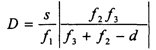
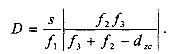
- the optical system operates so as to transform the starting dimension of the light beam in the considered direction, equal to n x s , into a dimension D , where D is defined by the following formula:
- the beam reaches a spatial uniformity of the energy (or power) density that is proportional to the number n of the lenses constituting the first component.
- the present invention comprises three optical components for each of the two orthogonal directions transversal to the propagation direction of the light beam.
- the following description will illustrate the operation principle that applies to the X direction, in which the concerned beam has a dimension dx , and can be extended to the Y direction, in which the beam has a dimension dy, by suitably exchanging the X and Y variables.
- Figure 1 shows a top plan schematic view of an arrangement according to this invention, wherein the light beam travels in left to right direction and it is homogenized in horizontal direction, namely in a direction parallel to the sheet.
- Figure 2 shows a perspective view of a possible arrangement according to this invention, in which the spatial homogenization is effected in both directions.
- the global dimensions of the first component are, therefore, equal to the dimensions of the light beam on which the arrangement according to this invention operates and its location will be such that its middle point will be coincident with the propagation axis of the light beam.
- These lenses are equal with respect to one another and have a focal length equal to f 1 .
- This first system of n lenses is aimed at dividing the light beam into n portions and it is designated as Divider ( horizontal or vertical, according to the direction along which it operates).
- the secondary light beams exiting from said first optical system will be incident on the second optical system that comprises a single cylindrical lens whose optical axis coincides with the propagation axis of the light beam and whose dimensions are such as to collect the whole light exiting from the lenses of the first optical component.
- This single lens is designated as Condenser.
- the focal length of this lens is equal to f 2 and the distance between this lens and the Divider component is equal to d dc .
- the third optical component is comprised of a further cylindrical lens having its optical axis coincident with the optical axis of the Condenser component and having suitable dimensions for containing the light exiting from the Condenser component as well as a focal length f 3 .
- zoom It is designated as Zoom and its distance from the Condenser component is d zc .
- all horizontal and vertical Divider components can be formed by a single element adapted to contemporaneously operate in both directions and consisting of a number of toroidal or spherical lenses higher than 1 for each direction.
- the horizontal and vertical Condenser components as well as the horizontal and vertical Zoom components can be respectively formed by a single toroidal or spherical lens.
- some optical components can be reflective rather than refractive components and in this case the optical axis of the Condenser and Zoom components can also be not coincident with the propagation axis of the light beam incident on the divider component.
- an attenuator component adapted to continuously vary the light power can be added to the refractive components (lenses) and/or reflective components (mirrors), in order to enable the optical system to vary the dimensions of the light beam, while its energy (or power) density is maintained by suitably operating said attenuator.
- a spatial filtering system for instance comprising slits, or holes in the case of a fly-eye divider, can be located in the planes where the secondary beams exiting from the horizontal and/or vertical divider are possibly focused, such spatial filtering system being adapted to prevent any diffractive or interferential effects on the focal plane of the homogenizer.
- Said prototype is formed by a Divider component comprising two lenses having a total width of 2.5 cm (so that each lens of the Divider has a width of 1,25 cm).
- the focal length of the lenses forming the Divider component is of 50 cm
- the focal length of the Condenser component is of 45 cm
- the focal length of the Zoom component is of 8 cm.
- the concerned optical system has been illuminated by the light generated by a He-Ne laser, with a gaussian intensity spatial profile having a half-width of about 3 cm.
- the distance between the Condenser and the Zoom components has been adjusted a first time at a value of 68 cm, so as to obtain a focalization at about 12 cm from the Zoom component with a beam basewidth of 6 mm, and a second time at a value of 55 cm, so as to obtain a focal plane at a distance of 40 cm from the Zoom component and a final beam basewidth of 45 mm.
- the whole dimension of the prototype apparatus, as measured from the Divider component to the focal plane, has been maintained within a distance of about 1 m.
- the measurement of the final dimensions of the homogenized beam has been effected by means of a semiconductor photodetector arranged upon a remotely controlled slide.
- the slide is controlled by a Personal Computer which provides for contemporaneously acquiring the position of the detector and its electrical signal, which is proportional to the intensity of the incident light.
- the so realized optical system transforms the 25 mm wide central part of a gaussian beam into a beam having a plane profile (with an intensity fluctuation of less than 10%) with a basewidth variable in the range of 6 to 45 mm. Furthermore, in the 45 mm case, a simulation program purposedly realized for theoretically studying this optical system forecasts that, by moving the measurement plane beyond the focal plane resulting from the equations, the beam ought still to be homogeneous and to have a greater extension.
- the characteristics of the prototype apparatus have been checked only in respect of a limited fraction of its capability, due to the fact that only a Zoom lens of small dimensions was available (about 3 cm width). With the other optical components unchanged and a Zoom component lens of at least 5 cm, the homogenized beam could vary at the base from 2.3 mm up to 18 cm, with a zooming factor of 78.
- the simulation program it is also possible to ascertain that, in the configuration in which the beam reaches a dimension of 18 cm, by displacing the measurement plane beyond the focal one, a homogeneous beam of over 30 cm could be obtained, with a zooming factor higher than 130.
- a light beam be available with a dimension of 6 cm in the horizontal direction and that it is to be transformed into a beam of 10 cm in a focal plane that is spaced from the Divider component by no more than 100 cm.
- a light beam of 6 cm, a Divider component comprising three lenses and a focal plane spaced from the Divider component by 100 cm are again assumed.
- the focal lengths f 1 , f 2 and f 3 equal to 8 cm, 100 cm and 45 cm, respectively, the minimum dimension obtainable on the focal plane is 8 cm and the maximum one is 24 cm, which means that an optical system according to this example assures a variability of 300% for the final linear dimensions of the light beam and consequently a variability up to 900% for the energy (or power) density.
- the minimum dimension obtainable at a distance of 1 m from the Divider component is 4 cm, while the maximum dimension is about 32 cm, with a zooming factor of 800%.
Landscapes
- Physics & Mathematics (AREA)
- Optics & Photonics (AREA)
- Engineering & Computer Science (AREA)
- General Physics & Mathematics (AREA)
- Plasma & Fusion (AREA)
- Mechanical Engineering (AREA)
- Lenses (AREA)
- Laser Surgery Devices (AREA)
- Physical Or Chemical Processes And Apparatus (AREA)
- Lasers (AREA)
- Non-Portable Lighting Devices Or Systems Thereof (AREA)
Abstract
Description
- a case in which the lenses forming the Horizontal and/or the Vertical divider are not equal, that is, they have different size si (i = 1, 2, ...n). In this case , each lens of the Horizontal and /or Vertical divider must have a focal length fi such that the ratio si/fi is constant for every i = 1, 2, ...n.
- a case in which the lenses forming the Horizontal Divider and the Vertical Divider are parts of a single system of toroidal lenses or, when the focal lengths connected with the two directions are identical, spherical lenses (the latter optical component is generally defined as "fly-eye");
- a case in which the lenses forming the Horizontal Condenser and the Vertical Condenser are parts of a single system of toroidal or spherical lenses;
- a case in which the lenses forming the Horizontal Zoom and the Vertical Zoom are parts of a single system of toroidal or spherical lenses;
- a case in which the above mentioned cases occur contemporaneously with spherical lenses: in this circumstance, the optical system operates in such a way that the final dimensions of the light beam fulfil a pre-established proportionality relationship between the two directions.

Claims (9)
- An optical system for reshaping and spatially homogenizing light beams with variable cross-section output, comprising six optical components, with three components associated to each of two orthogonal transverse directions, wherein the first component operates as a Divider component (D; DO, DV) and is formed by a number n of cylindrical lenses (D1, ...,Dn), where n is greater than 1, whose total dimension is not greater than the respective dimension of the light beam and whose middle point lies upon the optical axis of the light beam, the second component operates as a Condenser component (C; CO, CV) and is formed by a cylindrical lens and the third component operates as a Zoom component (Z; ZO; ZV) and is formed by a cylindrical lens, and wherein, in the case the cylindrical lenses (D1, ..Dn) have different size si (i = 1, 2,..n), the ratio size/focal length si/fi must be constant for every i = 1, 2, ...n .
- An optical system according to claim 1, wherein the Divider horizontal and vertical components are formed by a single component contemporaneously operating in the two directions, such component being comprised of a number of toroidal or spherical lenses greater than 1 for each direction.
- An optical system according to claims 1 and 2, wherein the Condenser horizontal and vertical components are formed by a single toroidal or spherical lens.
- An optical system according to claims 1, 2 and 3, wherein the Zoom horizontal and vertical components are formed by a single toroidal or spherical lens.
- An optical system according to any one of claims 1, 2, 3 or 4, wherein some components are formed by divergent lenses having a negative focal length.
- An optical system according to any one of claims 1, 2, 3, 4 or 5, wherein some or all of the optical components are reflective components and in this case the optical axes of the Condenser (C; CO, CV) and Zoom (Z; ZO, ZV) components can be not-coincident with the propagation axis of the light beam incident on said Divider component.
- An optical system according to any one of claims 1, 2, 3, 4, 5 or 6, wherein an attenuator component adapted to continuously vary the light power can be added to the refractive components (lenses) and/or reflective components (mirrors), in order to enable the optical system to vary the dimensions of the light beam, while its energy (or power) density is maintained by suitably operating said attenuator.
- An optical system according to any one of claims 1, 2, 3, 4, 5, 6 or 7, wherein a spatial filtration system, for instance comprising slits, or holes in the case of a fly-eye Divider component, can be located in the planes where the secondary beams exiting from the horizontal and/or vertical Divider component are possibly focused, such spatial filtration system being adapted to prevent diffractive or interferential effects on the focal plane of the homogenizer.
- An optical system according to any one of the preceding claims and substantially as described in the specification and shown in Figures 1 and 2 of the annexed drawings.
Applications Claiming Priority (2)
| Application Number | Priority Date | Filing Date | Title |
|---|---|---|---|
| IT2000RM000229A IT1316395B1 (en) | 2000-04-28 | 2000-04-28 | OPTICAL SYSTEM FOR SPACE HOMOGENIZATION OF LIGHT BEAMS, SUSPENDED WITH VARIABLE SECTION. |
| ITRM000229 | 2000-04-28 |
Publications (3)
| Publication Number | Publication Date |
|---|---|
| EP1150156A2 true EP1150156A2 (en) | 2001-10-31 |
| EP1150156A3 EP1150156A3 (en) | 2004-09-15 |
| EP1150156B1 EP1150156B1 (en) | 2006-08-30 |
Family
ID=11454694
Family Applications (1)
| Application Number | Title | Priority Date | Filing Date |
|---|---|---|---|
| EP00830807A Expired - Lifetime EP1150156B1 (en) | 2000-04-28 | 2000-12-06 | Optical system for homogenization of light beams, with variable cross-section output |
Country Status (5)
| Country | Link |
|---|---|
| US (1) | US6639728B2 (en) |
| EP (1) | EP1150156B1 (en) |
| AT (1) | ATE338289T1 (en) |
| DE (1) | DE60030411T2 (en) |
| IT (1) | IT1316395B1 (en) |
Cited By (3)
| Publication number | Priority date | Publication date | Assignee | Title |
|---|---|---|---|---|
| GB2422052A (en) * | 2004-12-23 | 2006-07-12 | Micromass Ltd | Mass spectrometer with cross sectionally controlled laser beam |
| WO2006067495A3 (en) * | 2004-12-23 | 2007-05-18 | Micromass Ltd | Mass spectrometer |
| EP2752689A1 (en) * | 2013-01-02 | 2014-07-09 | Jena-Optronik GmbH | Calibration device for the calibration of an extraterrestrial optical instrument and calibration method with this |
Families Citing this family (7)
| Publication number | Priority date | Publication date | Assignee | Title |
|---|---|---|---|---|
| US7372630B2 (en) * | 2001-08-17 | 2008-05-13 | Semiconductor Energy Laboratory Co., Ltd. | Laser, irradiation apparatus, laser irradiation method, and method for manufacturing semiconductor device |
| JP3977038B2 (en) * | 2001-08-27 | 2007-09-19 | 株式会社半導体エネルギー研究所 | Laser irradiation apparatus and laser irradiation method |
| US7210820B2 (en) * | 2003-05-07 | 2007-05-01 | Resonetics, Inc. | Methods and apparatuses for homogenizing light |
| KR100990251B1 (en) * | 2003-12-23 | 2010-10-26 | 엘지디스플레이 주식회사 | Laser optics including laser beam profile strain filter |
| US20080013182A1 (en) * | 2006-07-17 | 2008-01-17 | Joerg Ferber | Two-stage laser-beam homogenizer |
| WO2010056990A1 (en) * | 2008-11-14 | 2010-05-20 | The Trustees Of Columbia University In The City Of New York | Systems and methods for the crystallization of thin films |
| WO2013009550A2 (en) * | 2011-07-13 | 2013-01-17 | Bae Systems Integration And Electronic Systems Integration Inc. | Beam shaping and control apparatus |
Family Cites Families (9)
| Publication number | Priority date | Publication date | Assignee | Title |
|---|---|---|---|---|
| US4733944A (en) * | 1986-01-24 | 1988-03-29 | Xmr, Inc. | Optical beam integration system |
| US6560018B1 (en) * | 1994-10-27 | 2003-05-06 | Massachusetts Institute Of Technology | Illumination system for transmissive light valve displays |
| FR2737786B1 (en) * | 1995-08-11 | 1997-09-12 | Soc D Production Et De Rech Ap | OPTICAL DEVICE FOR HOMOGENEIZING A LASER BEAM |
| DE19632460C1 (en) * | 1996-08-12 | 1997-10-30 | Microlas Lasersystem Gmbh | Optical device for homogenisation of laser radiation |
| JPH10314970A (en) * | 1997-05-14 | 1998-12-02 | Tsunezo Sei | How to improve the uniformity of laser beam irradiation |
| US5844727A (en) * | 1997-09-02 | 1998-12-01 | Cymer, Inc. | Illumination design for scanning microlithography systems |
| JP4663047B2 (en) * | 1998-07-13 | 2011-03-30 | 株式会社半導体エネルギー研究所 | Laser irradiation apparatus and method for manufacturing semiconductor device |
| JP3919419B2 (en) * | 2000-03-30 | 2007-05-23 | キヤノン株式会社 | Illumination apparatus and exposure apparatus having the same |
| US6577429B1 (en) * | 2002-01-15 | 2003-06-10 | Eastman Kodak Company | Laser projection display system |
-
2000
- 2000-04-28 IT IT2000RM000229A patent/IT1316395B1/en active
- 2000-11-30 US US09/727,268 patent/US6639728B2/en not_active Expired - Fee Related
- 2000-12-06 EP EP00830807A patent/EP1150156B1/en not_active Expired - Lifetime
- 2000-12-06 DE DE60030411T patent/DE60030411T2/en not_active Expired - Lifetime
- 2000-12-06 AT AT00830807T patent/ATE338289T1/en not_active IP Right Cessation
Cited By (5)
| Publication number | Priority date | Publication date | Assignee | Title |
|---|---|---|---|---|
| GB2422052A (en) * | 2004-12-23 | 2006-07-12 | Micromass Ltd | Mass spectrometer with cross sectionally controlled laser beam |
| GB2422052B (en) * | 2004-12-23 | 2007-04-18 | Micromass Ltd | Mass spectrometer |
| WO2006067495A3 (en) * | 2004-12-23 | 2007-05-18 | Micromass Ltd | Mass spectrometer |
| US7851744B2 (en) | 2004-12-23 | 2010-12-14 | Micromass Uk Limited | Mass spectrometer |
| EP2752689A1 (en) * | 2013-01-02 | 2014-07-09 | Jena-Optronik GmbH | Calibration device for the calibration of an extraterrestrial optical instrument and calibration method with this |
Also Published As
| Publication number | Publication date |
|---|---|
| EP1150156A3 (en) | 2004-09-15 |
| DE60030411T2 (en) | 2007-04-12 |
| ITRM20000229A0 (en) | 2000-04-28 |
| ATE338289T1 (en) | 2006-09-15 |
| DE60030411D1 (en) | 2006-10-12 |
| US20010043399A1 (en) | 2001-11-22 |
| IT1316395B1 (en) | 2003-04-10 |
| US6639728B2 (en) | 2003-10-28 |
| EP1150156B1 (en) | 2006-08-30 |
| ITRM20000229A1 (en) | 2001-10-28 |
Similar Documents
| Publication | Publication Date | Title |
|---|---|---|
| US4733944A (en) | Optical beam integration system | |
| KR102700886B1 (en) | Laser line lighting | |
| KR100915273B1 (en) | Laser processing apparatus and laser processing method | |
| US8014427B1 (en) | Line imaging systems and methods for laser annealing | |
| US6639728B2 (en) | Optical system for homogenization of light beams, with variable cross-section output | |
| CA1188138A (en) | Optical beam concentrator | |
| TWI638253B (en) | Pulse width controller device and system | |
| KR20110041437A (en) | Beam forming apparatus and method | |
| JP2011048361A (en) | Diffractive laser beam homogenizer including photosensitive material and method for fabricating the same | |
| US20170184865A1 (en) | Optical beam conditioning device with coherence-breaking and beam transforming modules | |
| KR100834468B1 (en) | Laser heat treatment method and apparatus | |
| US20120153189A1 (en) | Optical system for generating a light beam for treating a substrate | |
| Schreiber et al. | High-brightness fiber-coupling schemes for diode laser bars | |
| Laskin et al. | Refractive beam shapers for material processing with high power single mode and multimode lasers | |
| CN116931286B (en) | Beam shaping module, method and device | |
| TWI844642B (en) | Device for generating a linear intensity distribution in a working plane | |
| US12095221B2 (en) | Diode-pumped solid state lasers | |
| JP7629087B2 (en) | Device for generating a defined laser line on a work surface | |
| US20240036338A1 (en) | Systems, devices, and methods for laser beam generation | |
| Bizjak et al. | Novel refractive optics enable multipole off-axis illumination | |
| JPS63153514A (en) | Light projecting device | |
| CN115113409A (en) | Linear flat-top light spot generation system, method and equipment based on Dammann grating | |
| Fuse | Flattop Beam Generation and Multibeam Processing Using Aspheric and Diffractive Optics. | |
| Unnebrink et al. | Optical system design for excimer laser materials processing | |
| KR100296386B1 (en) | Laser beam profile deformation method and apparatus and fiber optic grating processing method |
Legal Events
| Date | Code | Title | Description |
|---|---|---|---|
| PUAI | Public reference made under article 153(3) epc to a published international application that has entered the european phase |
Free format text: ORIGINAL CODE: 0009012 |
|
| AK | Designated contracting states |
Kind code of ref document: A2 Designated state(s): AT BE CH CY DE DK ES FI FR GB GR IE IT LI LU MC NL PT SE TR |
|
| AX | Request for extension of the european patent |
Free format text: AL;LT;LV;MK;RO;SI |
|
| PUAL | Search report despatched |
Free format text: ORIGINAL CODE: 0009013 |
|
| AK | Designated contracting states |
Kind code of ref document: A3 Designated state(s): AT BE CH CY DE DK ES FI FR GB GR IE IT LI LU MC NL PT SE TR |
|
| AX | Request for extension of the european patent |
Extension state: AL LT LV MK RO SI |
|
| 17P | Request for examination filed |
Effective date: 20041014 |
|
| 17Q | First examination report despatched |
Effective date: 20050308 |
|
| AKX | Designation fees paid |
Designated state(s): AT BE CH CY DE DK ES FI FR GB GR IE IT LI LU MC NL PT SE TR |
|
| GRAP | Despatch of communication of intention to grant a patent |
Free format text: ORIGINAL CODE: EPIDOSNIGR1 |
|
| GRAS | Grant fee paid |
Free format text: ORIGINAL CODE: EPIDOSNIGR3 |
|
| GRAA | (expected) grant |
Free format text: ORIGINAL CODE: 0009210 |
|
| AK | Designated contracting states |
Kind code of ref document: B1 Designated state(s): AT BE CH CY DE DK ES FI FR GB GR IE IT LI LU MC NL PT SE TR |
|
| PG25 | Lapsed in a contracting state [announced via postgrant information from national office to epo] |
Ref country code: IT Free format text: LAPSE BECAUSE OF FAILURE TO SUBMIT A TRANSLATION OF THE DESCRIPTION OR TO PAY THE FEE WITHIN THE PRE;WARNING: LAPSES OF ITALIAN PATENTS WITH EFFECTIVE DATE BEFORE 2007 MAY HAVE OCCURRED AT ANY TIME BEFORE 2007. THE CORRECT EFFECTIVE DATE MAY BE DIFFERENT FROM THE ONE RECORDED.SCRIBED TIME-LIMIT Effective date: 20060830 Ref country code: AT Free format text: LAPSE BECAUSE OF FAILURE TO SUBMIT A TRANSLATION OF THE DESCRIPTION OR TO PAY THE FEE WITHIN THE PRESCRIBED TIME-LIMIT Effective date: 20060830 Ref country code: NL Free format text: LAPSE BECAUSE OF FAILURE TO SUBMIT A TRANSLATION OF THE DESCRIPTION OR TO PAY THE FEE WITHIN THE PRESCRIBED TIME-LIMIT Effective date: 20060830 Ref country code: CH Free format text: LAPSE BECAUSE OF FAILURE TO SUBMIT A TRANSLATION OF THE DESCRIPTION OR TO PAY THE FEE WITHIN THE PRESCRIBED TIME-LIMIT Effective date: 20060830 Ref country code: LI Free format text: LAPSE BECAUSE OF FAILURE TO SUBMIT A TRANSLATION OF THE DESCRIPTION OR TO PAY THE FEE WITHIN THE PRESCRIBED TIME-LIMIT Effective date: 20060830 Ref country code: BE Free format text: LAPSE BECAUSE OF FAILURE TO SUBMIT A TRANSLATION OF THE DESCRIPTION OR TO PAY THE FEE WITHIN THE PRESCRIBED TIME-LIMIT Effective date: 20060830 Ref country code: FI Free format text: LAPSE BECAUSE OF FAILURE TO SUBMIT A TRANSLATION OF THE DESCRIPTION OR TO PAY THE FEE WITHIN THE PRESCRIBED TIME-LIMIT Effective date: 20060830 |
|
| REG | Reference to a national code |
Ref country code: GB Ref legal event code: FG4D |
|
| REG | Reference to a national code |
Ref country code: CH Ref legal event code: EP |
|
| REG | Reference to a national code |
Ref country code: IE Ref legal event code: FG4D |
|
| REF | Corresponds to: |
Ref document number: 60030411 Country of ref document: DE Date of ref document: 20061012 Kind code of ref document: P |
|
| PG25 | Lapsed in a contracting state [announced via postgrant information from national office to epo] |
Ref country code: SE Free format text: LAPSE BECAUSE OF FAILURE TO SUBMIT A TRANSLATION OF THE DESCRIPTION OR TO PAY THE FEE WITHIN THE PRESCRIBED TIME-LIMIT Effective date: 20061130 Ref country code: DK Free format text: LAPSE BECAUSE OF FAILURE TO SUBMIT A TRANSLATION OF THE DESCRIPTION OR TO PAY THE FEE WITHIN THE PRESCRIBED TIME-LIMIT Effective date: 20061130 |
|
| PG25 | Lapsed in a contracting state [announced via postgrant information from national office to epo] |
Ref country code: IE Free format text: LAPSE BECAUSE OF NON-PAYMENT OF DUE FEES Effective date: 20061206 |
|
| PG25 | Lapsed in a contracting state [announced via postgrant information from national office to epo] |
Ref country code: ES Free format text: LAPSE BECAUSE OF FAILURE TO SUBMIT A TRANSLATION OF THE DESCRIPTION OR TO PAY THE FEE WITHIN THE PRESCRIBED TIME-LIMIT Effective date: 20061211 |
|
| PG25 | Lapsed in a contracting state [announced via postgrant information from national office to epo] |
Ref country code: MC Free format text: LAPSE BECAUSE OF NON-PAYMENT OF DUE FEES Effective date: 20061231 |
|
| PG25 | Lapsed in a contracting state [announced via postgrant information from national office to epo] |
Ref country code: PT Free format text: LAPSE BECAUSE OF FAILURE TO SUBMIT A TRANSLATION OF THE DESCRIPTION OR TO PAY THE FEE WITHIN THE PRESCRIBED TIME-LIMIT Effective date: 20070212 |
|
| REG | Reference to a national code |
Ref country code: CH Ref legal event code: PL |
|
| NLV1 | Nl: lapsed or annulled due to failure to fulfill the requirements of art. 29p and 29m of the patents act | ||
| ET | Fr: translation filed | ||
| PLBE | No opposition filed within time limit |
Free format text: ORIGINAL CODE: 0009261 |
|
| STAA | Information on the status of an ep patent application or granted ep patent |
Free format text: STATUS: NO OPPOSITION FILED WITHIN TIME LIMIT |
|
| 26N | No opposition filed |
Effective date: 20070531 |
|
| PG25 | Lapsed in a contracting state [announced via postgrant information from national office to epo] |
Ref country code: GR Free format text: LAPSE BECAUSE OF FAILURE TO SUBMIT A TRANSLATION OF THE DESCRIPTION OR TO PAY THE FEE WITHIN THE PRESCRIBED TIME-LIMIT Effective date: 20061201 |
|
| PG25 | Lapsed in a contracting state [announced via postgrant information from national office to epo] |
Ref country code: TR Free format text: LAPSE BECAUSE OF FAILURE TO SUBMIT A TRANSLATION OF THE DESCRIPTION OR TO PAY THE FEE WITHIN THE PRESCRIBED TIME-LIMIT Effective date: 20060830 Ref country code: LU Free format text: LAPSE BECAUSE OF NON-PAYMENT OF DUE FEES Effective date: 20061206 |
|
| PG25 | Lapsed in a contracting state [announced via postgrant information from national office to epo] |
Ref country code: CY Free format text: LAPSE BECAUSE OF FAILURE TO SUBMIT A TRANSLATION OF THE DESCRIPTION OR TO PAY THE FEE WITHIN THE PRESCRIBED TIME-LIMIT Effective date: 20060830 |
|
| PGFP | Annual fee paid to national office [announced via postgrant information from national office to epo] |
Ref country code: FR Payment date: 20101224 Year of fee payment: 11 |
|
| PGFP | Annual fee paid to national office [announced via postgrant information from national office to epo] |
Ref country code: GB Payment date: 20101201 Year of fee payment: 11 |
|
| PGFP | Annual fee paid to national office [announced via postgrant information from national office to epo] |
Ref country code: DE Payment date: 20110218 Year of fee payment: 11 |
|
| GBPC | Gb: european patent ceased through non-payment of renewal fee |
Effective date: 20111206 |
|
| REG | Reference to a national code |
Ref country code: FR Ref legal event code: ST Effective date: 20120831 |
|
| REG | Reference to a national code |
Ref country code: DE Ref legal event code: R119 Ref document number: 60030411 Country of ref document: DE Effective date: 20120703 |
|
| PG25 | Lapsed in a contracting state [announced via postgrant information from national office to epo] |
Ref country code: GB Free format text: LAPSE BECAUSE OF NON-PAYMENT OF DUE FEES Effective date: 20111206 Ref country code: DE Free format text: LAPSE BECAUSE OF NON-PAYMENT OF DUE FEES Effective date: 20120703 |
|
| PG25 | Lapsed in a contracting state [announced via postgrant information from national office to epo] |
Ref country code: FR Free format text: LAPSE BECAUSE OF NON-PAYMENT OF DUE FEES Effective date: 20120102 |