EP1149990A2 - Blow-by gas separator - Google Patents
Blow-by gas separator Download PDFInfo
- Publication number
- EP1149990A2 EP1149990A2 EP01109425A EP01109425A EP1149990A2 EP 1149990 A2 EP1149990 A2 EP 1149990A2 EP 01109425 A EP01109425 A EP 01109425A EP 01109425 A EP01109425 A EP 01109425A EP 1149990 A2 EP1149990 A2 EP 1149990A2
- Authority
- EP
- European Patent Office
- Prior art keywords
- blow
- gas
- gas flow
- chamber
- port
- Prior art date
- Legal status (The legal status is an assumption and is not a legal conclusion. Google has not performed a legal analysis and makes no representation as to the accuracy of the status listed.)
- Granted
Links
- 230000004308 accommodation Effects 0.000 claims abstract description 42
- 230000002093 peripheral effect Effects 0.000 claims abstract description 19
- 238000000638 solvent extraction Methods 0.000 claims description 32
- 239000000463 material Substances 0.000 claims description 5
- 238000005192 partition Methods 0.000 claims description 3
- 239000007789 gas Substances 0.000 description 123
- 239000003921 oil Substances 0.000 description 31
- 239000000446 fuel Substances 0.000 description 12
- 238000002347 injection Methods 0.000 description 10
- 239000007924 injection Substances 0.000 description 10
- 238000003780 insertion Methods 0.000 description 10
- 230000037431 insertion Effects 0.000 description 10
- 229910000838 Al alloy Inorganic materials 0.000 description 4
- 238000007789 sealing Methods 0.000 description 3
- XEEYBQQBJWHFJM-UHFFFAOYSA-N Iron Chemical compound [Fe] XEEYBQQBJWHFJM-UHFFFAOYSA-N 0.000 description 2
- 238000002485 combustion reaction Methods 0.000 description 2
- 239000010687 lubricating oil Substances 0.000 description 2
- 229910052782 aluminium Inorganic materials 0.000 description 1
- XAGFODPZIPBFFR-UHFFFAOYSA-N aluminium Chemical compound [Al] XAGFODPZIPBFFR-UHFFFAOYSA-N 0.000 description 1
- 238000004512 die casting Methods 0.000 description 1
- 230000000694 effects Effects 0.000 description 1
- 239000002828 fuel tank Substances 0.000 description 1
- 229910052742 iron Inorganic materials 0.000 description 1
- 238000005461 lubrication Methods 0.000 description 1
- 229910052751 metal Inorganic materials 0.000 description 1
- 239000002184 metal Substances 0.000 description 1
- 239000007769 metal material Substances 0.000 description 1
- 238000000926 separation method Methods 0.000 description 1
- 238000009423 ventilation Methods 0.000 description 1
- XLYOFNOQVPJJNP-UHFFFAOYSA-N water Substances O XLYOFNOQVPJJNP-UHFFFAOYSA-N 0.000 description 1
Images



Classifications
-
- F—MECHANICAL ENGINEERING; LIGHTING; HEATING; WEAPONS; BLASTING
- F01—MACHINES OR ENGINES IN GENERAL; ENGINE PLANTS IN GENERAL; STEAM ENGINES
- F01M—LUBRICATING OF MACHINES OR ENGINES IN GENERAL; LUBRICATING INTERNAL COMBUSTION ENGINES; CRANKCASE VENTILATING
- F01M13/00—Crankcase ventilating or breathing
- F01M13/02—Crankcase ventilating or breathing by means of additional source of positive or negative pressure
- F01M13/021—Crankcase ventilating or breathing by means of additional source of positive or negative pressure of negative pressure
- F01M13/022—Crankcase ventilating or breathing by means of additional source of positive or negative pressure of negative pressure using engine inlet suction
-
- F—MECHANICAL ENGINEERING; LIGHTING; HEATING; WEAPONS; BLASTING
- F01—MACHINES OR ENGINES IN GENERAL; ENGINE PLANTS IN GENERAL; STEAM ENGINES
- F01M—LUBRICATING OF MACHINES OR ENGINES IN GENERAL; LUBRICATING INTERNAL COMBUSTION ENGINES; CRANKCASE VENTILATING
- F01M13/00—Crankcase ventilating or breathing
- F01M13/04—Crankcase ventilating or breathing having means for purifying air before leaving crankcase, e.g. removing oil
Definitions
- the present invention relates to a blow-by gas separator for separating and removing an oil contained in the blow-by gas of an engine.
- PCV positive crankcase ventilation
- the blow-by gas contains unburned gases as well as a lubricating oil which is in an atomized form, and it is necessary to separate and remove the oil.
- the PVC is provided with a separator which is usually arranged inside a cylinder head cover.
- the blow-by gas that has leaked into the crank case is guided into the separator through an oil chute passage that is formed in the side portion of the engine body and is opened in the upper surface of the cylinder head. While the blow-by gas thus guided into the separator passes through the separator, the oil is separated and removed therefrom and is recirculated into the intake system through the PCV hose.
- the separators are each provided in both cylinder head covers of the right and left banks and hence, the PCV hoses must be connected to the two separators and must be put together, resulting in an increase in the number of parts and causing the device to become complex.
- a blow-by gas separator comprising:
- the separator unit is constituted by a frame member with the accommodation space and a recessed portion as well as a cover member mounted on the recessed portion of the frame member and having a recessed portion to form the blow-by gas passage chamber in cooperation with the recessed portion of the frame member.
- a partitioning plate for partitioning the blow-by gas passage chamber into a blow-by gas flow-in chamber and a blow-by gas flow-out chamber is disposed between the frame member and the cover member.
- the partitioning plate has a passage port for communicating the blow-by gas flow-in chamber with the blow-by gas flow-out chamber, and a blow-by gas flow-in port is opened in the blow-by gas flow-in chamber and a blow-by gas flow-out port is opened in the blow-by gas flow-out chamber.
- blow-by gas flow-in port is formed at an upper location than the passage port of the partitioning plate and that the blow-by gas flow-in chamber is provided with a narrowed portion with a reduced cross section between the blow-by gas flow-in port and the passage port.
- the lower part of the blow-by gas flow-out chamber is communicated through an oil drain passage with the accommodation space for accommodating the drive mechanism.
- the partitioning plate is made of a metallic gasket material.
- the cylinder block has a pair of right and left banks which have offset relation to each other along the direction of the crank shaft, and the cover member is arranged in space produced by the offset of the right and left banks.
- reference numeral 10 denotes an engine body which is constituted by a cylinder block 11 and cylinder heads 12, 12.
- the cylinder block 11 is a V-type one in which a pair of right and left banks 11a and 11b are opposed to each other to form V-banks.
- Three cylinders are formed in each of the right and left banks 11a and 11b of the cylinder block 11.
- the cylinders formed in the right and left banks 11a and 11b are alternately arranged in the direction of the crank shaft to prevent interference between the connection rods arranged on the crank shaft.
- the right and left banks 11a and 11b have offset relation to each other by a length T of the offset in the direction of the crank shaft.
- the bank 11b on the right side as viewed from the front of the engine body 10 (lower side in Fig. 2) is placed on the rear side of the engine (right side in Fig. 3) by the length T relative to the bank 11a of the left side as viewed from the front of the engine body 10.
- a blow-by gas discharge port 25 is provided at a central portion between the V-banks of the cylinder block 11 constituted as described above.
- the blow-by gas discharge port 25 is communicated with a blow-by gas discharge passage (not shown) that is opened in the crank case of the cylinder block 11. Therefore, the blow-by gas filled in the crank case is sent to a separator that will be described later, from the blow-by gas discharge port 25 through the blow-by gas discharge passage that is not shown.
- Cylinder heads 12, 12 are placed on the upper surfaces of the right and left banks 11a and 11b that constitute the cylinder block 11.
- Head bolt holes 13 are formed in the cylinder heads 12 and 12 along the periphery thereof, and head bolts that are not shown are inserted in the head bolt holes 13 and are screwed into threaded holes formed in the right and left banks 11a and 11b, so that the cylinder heads 12 and 12 are fastened to the cylinder block 11.
- Intake manifolds 14 and 14 are arranged on the opposing inner sides of the cylinder heads 12 and 12. Ends on one side of the intake manifolds 14 and 14 are coupled to intake ports (not shown) that are opened in the cylinder heads 12 and 12, and ends on the other side thereof are coupled to intake branch pipes 15a and 15a.
- the two intake branch pipes 15a and 15a are put together into one so as to be coupled to an intake pipe 15.
- a fuel injection pump 16 at a front end thereof (left end in Fig. 2).
- the fuel injection pump 16 raises the pressure of the fuel fed, by a feed pump, from a fuel tank that is not shown, and feeds this high-pressure fuel to fuel injection nozzles disposed in the cylinders.
- a drive shaft 17 of the fuel injection pump 16 is disposed protruding forward beyond a front end surface 100 of the engine body 10.
- a pump gear 18 is attached to an end of the rive shaft 17.
- Two idler gears 21 and 22 are arranged between the crank gear 20 and the pump gear 18 to be in mesh with two gears, whereby the crank gear 20 is coupled to the pump gear 18 through a gearing.
- the crank gear 20, idler gears 21, 22 and pump gear 18 constitute a drive mechanism for transmitting the driving force of the crank shaft 19 to the drive shaft 17, which is a driven shaft, of the fuel injection pump 16.
- a separator unit 30 is mounted on the front end surface 100 of the engine body 10 to constitute a blow-by gas separator.
- the separator unit 30 has a frame member 40.
- the frame member 40 will now be described with reference chiefly to Fig. 3.
- the frame member 40 is constituted by a plate-like member formed of, for example, an aluminum alloy and having a predetermined thickness.
- the frame member 40 is formed in a shape nearly in agreement with the shape of the front end surface 100 of the engine body 10 and has a central portion which protrudes upward.
- an accommodation space 41 in which is arranged the drive mechanism that transmits the driving force of the crank shaft 19 to the drive shaft 17, which is the driven shaft, of the fuel injection pump 16, i.e., in which are arranged the crank gear 20, idler gears 21, 22 and pump gear 18.
- the accommodation space 41 is constituted by a vertically elongated nearly elliptic hole from the lower part of the frame member 40 toward the central part thereof.
- the crank gear 20, idler gears 21, 22 and pump gear 18 are arranged in the accommodation space 41 at a positional relationship shown by two-dot chain lines in Fig. 3 in a state where the separator unit 30 is mounted on the front end surface 100 of the engine body 10.
- a protection wall 42 is formed hanging from the upper part of the accommodation space 41 on the side of the rear end surface of the frame member 40 (front side in Fig. 3).
- the protection wall 42 is provided for preventing the oil that lubricates the gears constituting the drive mechanism for the fuel injection pump 16 from flying in a direction of between the V-banks of the cylinder block 11. Therefore, the upper part of the accommodation space 41 is closed by the protection wall 42 on the side of the rear end surface, and a space defined on the front side of the protection wall 42 (back side in Fig 3) serves a space for arranging part of the pump
- the frame member 40 has a plurality of frame member-mounting bosses 43, 44 for fastening it to the engine body 10 by using fastening bolts.
- the frame member-mounting bosses 43 corresponding to the cylinder block 11 are formed along the outer peripheral edge of the accommodation space 41 and along the lower end of the protection wall 42.
- the frame member-mounting bosses 44 corresponding to the cylinder heads 12,12 are formed along the outer peripheral edge of the frame member 40.
- the frame member-mounting bosses 44 include frame member-mounting bosses 44a formed at portions corresponding to the cylinder head 12 of the left side (right side in Fig.
- the accommodation space 41 is formed in the frame member 40.
- a front cover 50 is mounted on the front surface of the accommodation space 41 as shown in Figs. 1 and 2.
- the front cover 50 is formed of a plate member of, for example, an aluminum alloy having a thickness smaller than that of the frame member 40 and is formed in a shape that meets the outer peripheral edge of the accommodation space 41.
- the front cover 50 has a plurality of mounting bosses 51 formed along the peripheral edge thereof, the plural mounting bosses 51 having insertion holes for fastening the front cover 50 to the frame member 40 by using the fastening bolts.
- the peripheral edge of the front cover 50 is overlapped on the outer peripheral edge of the accommodation space 41 of the frame member 40, the fastening bolts are inserted in the insertion holes formed in the mounting bosses 51, and the fastening bolts are screwed into threaded holes (not shown) formed in the outer peripheral edge of the accommodation space 41 of the frame member 40 to mount the front cover 50 on the front surface of the accommodation space 41 of the frame member 40. Therefore, the front cover 50 is so mounted on the front surface of the accommodation space 41 formed in the frame member 40 as to serve as a closure.
- the front cover 50 that is mounted on the front surface of the accommodation space 41 of the frame member 40 covers the crank gear 20, idler gears 21, 22 and pump gear 18 constituting the drive mechanism of the fuel injection pump 16 accommodated in the accommodation space 41.
- the front cover 50 which is a separate member is mounted on the front surface of the accommodation space 41 in the frame member 40.
- the accommodation space 41 may be formed by a member formed as a unitary structure which includes the frame member 40 and the front cover 50.
- an aluminum alloy is used as a material of the frame member 40 and the front cover 50 from the standpoint of reducing the weight. Not being limited to the aluminum alloy, however, there may be used iron-based metal or other metal materials.
- the frame member 40 having the accommodation space 41 for accommodating the drive mechanism is provided with a recessed portion 46 that constitutes a blow-by gas passage chamber 31 of the separator on the upper side of the accommodation space 41.
- the recessed portion 46 is formed along the outer peripheral edge in the upper part of the accommodation space 41.
- the recessed portion 46 is formed like a belt from the left upper part through up to the central upper part as viewed from the back surface (from the left upper part through up to the central upper part in Fig. 3).
- the recessed portion 46 is horizontal on the right side and is tilted down on the left side.
- the recessed portion 46 is open on the rear surface side of the frame member 40 (right side in Fig. 6) and has nearly a constant depth.
- the frame member 40 has a cover member-mounting seat 401 that serves as a seat surface for mounting a cover member 60 that will be described later along the outer peripheral edge of the recessed portion 46.
- the cover member-mounting seat 401 is formed on the side of the rear end surface of the frame member 40, i.e., on the side of the open surface of the recessed portion 46.
- the cover member-mounting seat 401 has plural cover member-mounting bosses 402 with threaded holes, and the cover member 60 is mounted on the cover member-mounting bosses 402 by using the fastening bolts.
- the above-mentioned frame member-mounting bosses 44b, too, are formed in the cover member-mounting seat 401.
- the cover member 60 mounted on the cover member-mounting seat 401 of the frame member 40 has a recessed portion 61.
- the blow-by gas passage chamber 31 is constituted by the recessed portion 61 in the cover member 60 and by the recessed portion 46 in the frame member 40.
- a partitioning plate 70 having a passage port 71 is disposed between the frame member 40 and the cover member 60. The partitioning plate 70 partitions the blow-by gas passage chamber 31 into a blow-by gas flow-in chamber 32a and a blow-by gas flow-out chamber 32b and the passage port 71 communicates the blow-by gas flow-in chamber 32a with the blow-by gas flow-out chamber 32b.
- the cover member 60 having the recessed portion 61 will now be described with reference to Figs. 4 and 6.
- the cover member 60 is formed of, for example, an aluminum die casting.
- the cover member 60 has plural mounting portions 64 for mounting it on the cover member-mounting seat 401 of the frame member 40.
- the mounting portions 64 corresponding to the cover member-mounting bosses 402 formed in the cover member-mounting seat 401 of the frame member 40 are formed along the outer peripheral edge of the cover member 60 and have holes for inserting the fastening bolts.
- Fastening bolts 80 are inserted in the holes and are screwed into the threaded holes formed in the cover member-mounting bosses 402 of the frame member 40 thereby to mount the cover member 60 on the frame member 40.
- the blow-by gas flow-in port 62 and the blow-by gas discharge port 25 are communicated with each other via a pipe 26 connected to the joint flange 63. Further, the blow-by-gas flow-in chamber 32a formed by the recessed portion 61 and the partitioning plate 70 is provided with a narrowed portion 66 having a reduced cross section between the blow-by gas flow-in port 62 and the passage port 71.
- the thus constituted cover member 60 in a state of being mounted on the frame member 40, is placed in a space formed by the offset of the right and left banks 11a and 11b of the cylinder block 11 that constitutes the engine body 10.
- the partitioning plate 70 is constituted by a sheet-like member which is a metallic gasket material.
- the partitioning plate 70 has a shape that meets the recessed portion 46 of the frame member 40.
- the passage port 71 is formed in the partitioning plate 70 in the right lower portion thereof in Fig. 5. Therefore, the blow-by gas flow-in chamber 32a and the blow-by gas flow-out chamber 32b partitioned by the partitioning plate 70 are communicated with each other through the passage port 71.
- the partitioning plate 70 has a plurality of bolt insertion holes 73 formed in the outer peripheral edge portion thereof for allowing insertion of the fastening bolts 80.
- the frame member 40 is provided with a blow-by gas flow-out port 47 opened at an upper position in the blow-by gas flow-out chamber 32b defined by the recessed portion 46 and the partitioning plate 70.
- a hose connection member 48 is fitted to the blow-by gas flow-out port 47 and, as shown in Figs. 1 and 2, the blow-by gas flow-out port 47 is communicated with the intake pipe 15 via the PCV hose 27 connected to the hose connection member 48.
- an oil drain passage 49 for communicating a lower part of the blow-by gas flow-out chamber 32b with the accommodation space 41.
- the oil drain port 49 is provided for draining the oil separated from the blow-by gas in the blow-by gas passage chamber 31 as will be described later.
- blow-by gas separator according to the illustrated embodiment is constituted as described above, and its operation will now be described.
- the blow-by gas filled in the crank case of the cylinder block 11 is discharged from the blow-by gas discharge port 25 formed between the V-banks of the cylinder block 11, and flows into the blow-by gas flow-in chamber 32a that constitutes the separator via the pipe 26.
- the blow-by gas that has flowed into the blow-by gas flow-in chamber 32a comes in contact with the partitioning plate 70 and is deflected downward as shown in Fig. 6.
- the blow-by gas that flows down through the blow-by gas flow-in chamber 32a increases its velocity of flow when it passes through the narrowed portion 66, and flows down to the lower end.
- blow-by gas flowing down toward the lower end of the blow-by gas flow-in chamber 32a is guided into the blow-by gas flow-out chamber 32b through the passage port 71 formed at the lower end of the partitioning plate 70.
- the blow-by gas greatly changes its direction.
- the oil having a large mass, that is contained in the blow-by gas adheres to the wall on the lower side of the recessed portion 61 constituting the blow-by gas flow-in chamber 32a due to its inertia force, and is separated.
- the oil is thus separated by the inertia force at the time when the blow-by gas changes its direction.
- the blow-by gas increases its velocity of flow at the time of passing through the narrowed portion 64 as described above, therefore, an increased effect of separation is exhibited.
- blow-by gas from which the oil is separated as described above flows into the blow-by gas flow-out chamber 32b and, then, flows upward toward the blow-by gas flow-out port 47.
- the blow-by gas is then sent into the intake pipe 15 through the hose connection member 48 fitted to the blow-by gas flow-out port 47 and the PCV hose 27.
- the oil separated from the blow-by gas flows into the blow-by gas flow-out chamber 32b through the communication port 71 formed at the lower end of the partitioning plate 70, and is drained to the accommodation space 41 through the oil drain passage 49 that communicates the accommodation space 41 with the lower part of the recessed portion 46 constituting the blow-by gas flow-out chamber 32b.
- the oil separated from the blow-by gas needs to be returned back to the lubrication system, and the oil drained into the accommodation space 41 through the oil drain passage 49 functions as a lubricating oil for the gears constituting the drive mechanism accommodated in the accommodation space 41.
- the blow-by gas separator according to the illustrated embodiment is constituted as described above, and the blow-by gas passage chamber 31 formed in the separator unit 30 having the accommodation space 41 for accommodating the drive mechanism, is formed along the outer peripheral edge of the upper portion of the accommodation space 41. Accordingly, the blow-by gas passage chamber 31 can be freely defined without imposing any limitation on the space for passing the blow-by gas.
- the blow-by gas passage chamber 31 secures space large enough for separating the oil contained in the blow-by gas, and the blow-by gas can be directly introduced from the blow-by gas flow-in port 62 without passing through the accommodation space accommodating the drive mechanism in which the oil is splashed.
- the blow-by gas passage chamber 31 is constituted by the recessed portion 46 formed in the frame member 40 and by the recessed portion 61 formed in the cover member 60, making it easy to form a space for flowing the blow-by gas.
- the partitioning plate 70 having the passage port 71 is disposed between the frame member 40 and the cover member 60 to partition the blow-by gas passage chamber 31 into the blow-by gas flow-in chamber 32a and the blow-by gas flow-out chamber 32b and to communicate the blow-by gas flow-in chamber 32a with the blow-by gas flow-out chamber 32b.
- the blow-by gas flow-in port 62 is located at an upper location than the passage port 71.
- the cover member 60 that constitutes the blow-by gas passage chamber 31 is placed in a space formed by the offset of the right and left banks 11a and 11b of the cylinder block 11 and hence, the blow-by gas passage chamber 31 can be formed by effectively utilizing this vacant space.
- the drive mechanism for transmitting the driving power of the crank shaft to the driven shaft was the gear-type drive mechanism for driving the driven shaft of the fuel injection pump.
- the drive mechanism may be a cam shaft, an oil pump or a water pump, and a system of driving the drive mechanism may be a belt or a chain.
- the recessed portion of the frame member constituting the blow-by gas passage chamber may be formed in the front surface of the frame member instead of in the back surface.
- the blow-by gas flow-in port was formed in the cover member and the blow-by gas flow-out port was formed in the frame member.
- the narrowed portion formed in the cover member had the reduced sectional area of the blow-by gas passage space by narrowing the width of the recessed portion formed in the cover member.
- the sectional area may be reduced by changing the depth of the recessed portion or by protruding the partitioning plate toward the cover member.
- the present invention may be put into practice in any form of embodiment provided that it is equipped with the requirements that constitute the present invention and exhibits the same action as that of the present invention.
- the blow-by gas separator of the present invention comprises a separator unit which is mounted on the front end surface of the cylinder block and has accommodation space for accommodating a drive mechanism that transmits the driving force of the crank shaft of an engine to a driven shaft, and the separator unit is provided with a blow-by gas passage chamber formed independently along the outer peripheral edge of the accommodation space. Accordingly, it is allowed to secure a sufficiently wide space in the separator and to reliably separate and remove the oil from the blow-by gas.
Landscapes
- Engineering & Computer Science (AREA)
- Mechanical Engineering (AREA)
- General Engineering & Computer Science (AREA)
- Lubrication Details And Ventilation Of Internal Combustion Engines (AREA)
- Cylinder Crankcases Of Internal Combustion Engines (AREA)
Abstract
Description
- The present invention relates to a blow-by gas separator for separating and removing an oil contained in the blow-by gas of an engine.
- There has heretofore been known a PCV (positive crankcase ventilation) for returning a blow-by gas that has leaked into a crank case from a combustion chamber of an engine through a gap between a piston and a cylinder wall, back to the combustion chamber to burn it. The blow-by gas contains unburned gases as well as a lubricating oil which is in an atomized form, and it is necessary to separate and remove the oil. For the purpose of separating and removing the oil, the PVC is provided with a separator which is usually arranged inside a cylinder head cover. In the PVC in which the separator is arranged inside the cylinder head cover, the blow-by gas that has leaked into the crank case is guided into the separator through an oil chute passage that is formed in the side portion of the engine body and is opened in the upper surface of the cylinder head. While the blow-by gas thus guided into the separator passes through the separator, the oil is separated and removed therefrom and is recirculated into the intake system through the PCV hose. In the case of the V-type engine, however, the separators are each provided in both cylinder head covers of the right and left banks and hence, the PCV hoses must be connected to the two separators and must be put together, resulting in an increase in the number of parts and causing the device to become complex. In order to solve this problem, there has been proposed a PVC, of which a separator is provided in a chain case that covers a timing chain provided at a front end of the engine as disclosed in Japanese Laid-open Patent Publications (Kokai) Nos. 98924/1993 (JP-A 5-98924) and 47157/1998 (JP-A 10-47157). With the separator being provided in the chain case at the front end of the engine, the blow-by gas that is introduced from the crank case into the separator to separate and remove the oil, can be returned back to the intake system through a single PCV hose, solving the above-mentioned problem peculiar to the V-type engines.
- However, there exist actually a chain, a sprocket, a tensioner and the like in the chain case and with relation with this fact, limitation is put on a space where the separator is arranged. That is, there exists a problem in that it is not allowed to secure a space enough for separating and removing the oil. Further, in the chain case, the oil circulates to lubricate the chain. When the blow-by gas flows through the chain case, therefore, the oil in the chain case intermingles with the blow-by gas. Namely, a problem arises that the oil can be hardly separated and removed from the blow-by gas to a sufficient degree and flows into the intake system.
- It is an object of the present invention to provide a blow-by gas separator that can secure a space enough for arranging the separator, can reliably separate and remove the oil from the blow-by gas and can prevent the oil from flowing into the intake system.
- In order to accomplish the above-mentioned object according to the present invention, there is provided a blow-by gas separator comprising:
- a separator unit mounted on a front end surface of a cylinder block and having accommodation space for accommodating a drive mechanism that transmits a driving force of the crank shaft of an engine to a driven shaft; wherein
- the separator unit is provided with a blow-by gas passage chamber formed along the outer peripheral edge of an upper part of the accommodation space, and has, formed therein, a blow-by gas flow-in port and a blow-by gas flow-out port, which are opened in the blow-by gas passage chamber.
-
- The separator unit is constituted by a frame member with the accommodation space and a recessed portion as well as a cover member mounted on the recessed portion of the frame member and having a recessed portion to form the blow-by gas passage chamber in cooperation with the recessed portion of the frame member.
- Further, a partitioning plate for partitioning the blow-by gas passage chamber into a blow-by gas flow-in chamber and a blow-by gas flow-out chamber is disposed between the frame member and the cover member. The partitioning plate has a passage port for communicating the blow-by gas flow-in chamber with the blow-by gas flow-out chamber, and a blow-by gas flow-in port is opened in the blow-by gas flow-in chamber and a blow-by gas flow-out port is opened in the blow-by gas flow-out chamber.
- It is desired that the blow-by gas flow-in port is formed at an upper location than the passage port of the partitioning plate and that the blow-by gas flow-in chamber is provided with a narrowed portion with a reduced cross section between the blow-by gas flow-in port and the passage port.
- Further, the lower part of the blow-by gas flow-out chamber is communicated through an oil drain passage with the accommodation space for accommodating the drive mechanism.
- It is further desired that the partitioning plate is made of a metallic gasket material.
- Further, the cylinder block has a pair of right and left banks which have offset relation to each other along the direction of the crank shaft, and the cover member is arranged in space produced by the offset of the right and left banks.
-
- Fig. 1 is a front view of an engine equipped with a blow-by gas separator constituted according to the present invention;
- Fig. 2 is a plan view of the engine of Fig. 1;
- Fig. 3 is a back view of a frame member that constitutes the blow-by gas separator in the engine of Fig. 1;
- Fig. 4 is a perspective view of a cover member that constitutes the blow-by gas separator in the engine of Fig. 1;
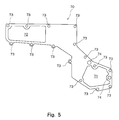
- Fig. 5 is a front view of a partitioning plate that constitutes the blow-by gas separator in the engine of Fig. 1; and
- Fig. 6 is a sectional view along the line I-I in Fig. 1.
-
- An embodiment of the present invention will now be described with reference to the drawings.
- The illustrated embodiment illustrates a case where the present invention is applied to a V-type 6-cylinder engine. In the drawings,
reference numeral 10 denotes an engine body which is constituted by acylinder block 11 andcylinder heads cylinder block 11 is a V-type one in which a pair of right andleft banks left banks cylinder block 11. The cylinders formed in the right andleft banks left banks bank 11b on the right side as viewed from the front of the engine body 10 (lower side in Fig. 2) is placed on the rear side of the engine (right side in Fig. 3) by the length T relative to thebank 11a of the left side as viewed from the front of theengine body 10. - Referring to Fig. 2, a blow-by
gas discharge port 25 is provided at a central portion between the V-banks of thecylinder block 11 constituted as described above. The blow-bygas discharge port 25 is communicated with a blow-by gas discharge passage (not shown) that is opened in the crank case of thecylinder block 11. Therefore, the blow-by gas filled in the crank case is sent to a separator that will be described later, from the blow-bygas discharge port 25 through the blow-by gas discharge passage that is not shown. -
Cylinder heads left banks cylinder block 11.Head bolt holes 13 are formed in thecylinder heads head bolt holes 13 and are screwed into threaded holes formed in the right andleft banks cylinder heads cylinder block 11.Intake manifolds cylinder heads intake manifolds cylinder heads intake branch pipes intake branch pipes intake pipe 15. - Between the V-banks of the
engine body 10 constituted by thecylinder block 11 and thecylinder heads fuel injection pump 16 at a front end thereof (left end in Fig. 2). Thefuel injection pump 16 raises the pressure of the fuel fed, by a feed pump, from a fuel tank that is not shown, and feeds this high-pressure fuel to fuel injection nozzles disposed in the cylinders. Adrive shaft 17 of thefuel injection pump 16 is disposed protruding forward beyond afront end surface 100 of theengine body 10. Apump gear 18 is attached to an end of therive shaft 17. Acrank shaft 19 arranged in a lower part of thecylinder block 11, too, protrudes forward beyond thefront end surface 100 of theengine body 10, and acrank gear 20 is attached to an end thereof. Twoidler gears crank gear 20 and thepump gear 18 to be in mesh with two gears, whereby thecrank gear 20 is coupled to thepump gear 18 through a gearing. Thus, thecrank gear 20,idler gears pump gear 18 constitute a drive mechanism for transmitting the driving force of thecrank shaft 19 to thedrive shaft 17, which is a driven shaft, of thefuel injection pump 16. - A
separator unit 30 is mounted on thefront end surface 100 of theengine body 10 to constitute a blow-by gas separator. - The
separator unit 30 has aframe member 40. Theframe member 40 will now be described with reference chiefly to Fig. 3. Theframe member 40 is constituted by a plate-like member formed of, for example, an aluminum alloy and having a predetermined thickness. Theframe member 40 is formed in a shape nearly in agreement with the shape of thefront end surface 100 of theengine body 10 and has a central portion which protrudes upward. In the thus formedframe member 40 is further formed anaccommodation space 41 in which is arranged the drive mechanism that transmits the driving force of thecrank shaft 19 to thedrive shaft 17, which is the driven shaft, of thefuel injection pump 16, i.e., in which are arranged thecrank gear 20,idler gears pump gear 18. Theaccommodation space 41 is constituted by a vertically elongated nearly elliptic hole from the lower part of theframe member 40 toward the central part thereof. Thecrank gear 20, idler gears 21, 22 andpump gear 18 are arranged in theaccommodation space 41 at a positional relationship shown by two-dot chain lines in Fig. 3 in a state where theseparator unit 30 is mounted on thefront end surface 100 of theengine body 10. Aprotection wall 42 is formed hanging from the upper part of theaccommodation space 41 on the side of the rear end surface of the frame member 40 (front side in Fig. 3). Theprotection wall 42 is provided for preventing the oil that lubricates the gears constituting the drive mechanism for the fuel injection pump 16 from flying in a direction of between the V-banks of thecylinder block 11. Therefore, the upper part of theaccommodation space 41 is closed by theprotection wall 42 on the side of the rear end surface, and a space defined on the front side of the protection wall 42 (back side in Fig 3) serves a space for arranging part of thepump gear 18. - The
frame member 40 has a plurality of frame member-mountingbosses 43, 44 for fastening it to theengine body 10 by using fastening bolts. The frame member-mountingbosses 43 corresponding to thecylinder block 11 are formed along the outer peripheral edge of theaccommodation space 41 and along the lower end of theprotection wall 42. On the other hand, the frame member-mounting bosses 44 corresponding to the cylinder heads 12,12 are formed along the outer peripheral edge of theframe member 40. The frame member-mounting bosses 44 include frame member-mountingbosses 44a formed at portions corresponding to thecylinder head 12 of the left side (right side in Fig. 3) as viewed from the front of theengine body 10 and frame member-mountingbosses 44b formed at portions corresponding to thecylinder head 12 of the right side (left side in Fig. 3). Bolt insertion holes are formed in these frame member-mountingbosses - On the back surface of the
frame member 40, ajunction portion 45 is provided along the outer peripheral edge of theaccommodation space 41 and along the lower end edge of theprotection wall 42. A slender groove is formed along the outer peripheral edge of theaccommodation space 41 and along the lower end edge of theprotection wall 42 in thejunction portion 45, and a sealing member of rubber or the like is fitted in the groove. When theseparator unit 30 is mounted on theengine body 10, the sealing member prevents the oil that lubricates the gears constituting the drive mechanism for the fuel injection pump 16 from leaking to the outer side through a gap between theseparator unit 30 and thecylinder block 11. - As described above, the
accommodation space 41 is formed in theframe member 40. In the illustrated embodiment, afront cover 50 is mounted on the front surface of theaccommodation space 41 as shown in Figs. 1 and 2. Thefront cover 50 is formed of a plate member of, for example, an aluminum alloy having a thickness smaller than that of theframe member 40 and is formed in a shape that meets the outer peripheral edge of theaccommodation space 41. Thefront cover 50 has a plurality of mountingbosses 51 formed along the peripheral edge thereof, theplural mounting bosses 51 having insertion holes for fastening thefront cover 50 to theframe member 40 by using the fastening bolts. The peripheral edge of thefront cover 50 is overlapped on the outer peripheral edge of theaccommodation space 41 of theframe member 40, the fastening bolts are inserted in the insertion holes formed in the mountingbosses 51, and the fastening bolts are screwed into threaded holes (not shown) formed in the outer peripheral edge of theaccommodation space 41 of theframe member 40 to mount thefront cover 50 on the front surface of theaccommodation space 41 of theframe member 40. Therefore, thefront cover 50 is so mounted on the front surface of theaccommodation space 41 formed in theframe member 40 as to serve as a closure. Thefront cover 50 that is mounted on the front surface of theaccommodation space 41 of theframe member 40, covers thecrank gear 20, idler gears 21, 22 andpump gear 18 constituting the drive mechanism of thefuel injection pump 16 accommodated in theaccommodation space 41. - In the illustrated embodiment, the
front cover 50 which is a separate member is mounted on the front surface of theaccommodation space 41 in theframe member 40. However, theaccommodation space 41 may be formed by a member formed as a unitary structure which includes theframe member 40 and thefront cover 50. Further, an aluminum alloy is used as a material of theframe member 40 and thefront cover 50 from the standpoint of reducing the weight. Not being limited to the aluminum alloy, however, there may be used iron-based metal or other metal materials. - Referring to Fig. 3, the
frame member 40 having theaccommodation space 41 for accommodating the drive mechanism, is provided with a recessedportion 46 that constitutes a blow-bygas passage chamber 31 of the separator on the upper side of theaccommodation space 41. The recessedportion 46 is formed along the outer peripheral edge in the upper part of theaccommodation space 41. In the illustrated embodiment, the recessedportion 46 is formed like a belt from the left upper part through up to the central upper part as viewed from the back surface (from the left upper part through up to the central upper part in Fig. 3). In Fig. 3, the recessedportion 46 is horizontal on the right side and is tilted down on the left side. Referring to Fig. 6, further, the recessedportion 46 is open on the rear surface side of the frame member 40 (right side in Fig. 6) and has nearly a constant depth. - The
frame member 40 has a cover member-mountingseat 401 that serves as a seat surface for mounting acover member 60 that will be described later along the outer peripheral edge of the recessedportion 46. The cover member-mountingseat 401 is formed on the side of the rear end surface of theframe member 40, i.e., on the side of the open surface of the recessedportion 46. The cover member-mountingseat 401 has plural cover member-mountingbosses 402 with threaded holes, and thecover member 60 is mounted on the cover member-mountingbosses 402 by using the fastening bolts. The above-mentioned frame member-mountingbosses 44b, too, are formed in the cover member-mountingseat 401. - The
cover member 60 mounted on the cover member-mountingseat 401 of theframe member 40 has a recessedportion 61. The blow-bygas passage chamber 31 is constituted by the recessedportion 61 in thecover member 60 and by the recessedportion 46 in theframe member 40. Apartitioning plate 70 having apassage port 71 is disposed between theframe member 40 and thecover member 60. Thepartitioning plate 70 partitions the blow-bygas passage chamber 31 into a blow-by gas flow-inchamber 32a and a blow-by gas flow-outchamber 32b and thepassage port 71 communicates the blow-by gas flow-inchamber 32a with the blow-by gas flow-outchamber 32b. - The
cover member 60 having the recessedportion 61 will now be described with reference to Figs. 4 and 6. Thecover member 60 is formed of, for example, an aluminum die casting. Thecover member 60 has plural mountingportions 64 for mounting it on the cover member-mountingseat 401 of theframe member 40. The mountingportions 64 corresponding to the cover member-mountingbosses 402 formed in the cover member-mountingseat 401 of theframe member 40 are formed along the outer peripheral edge of thecover member 60 and have holes for inserting the fastening bolts. Fasteningbolts 80 are inserted in the holes and are screwed into the threaded holes formed in the cover member-mountingbosses 402 of theframe member 40 thereby to mount thecover member 60 on theframe member 40. Thecover member 60 has bolt insertion holes 65 which, when theseparator unit 30 is mounted on thefront end surface 100 of theengine body 10, permit the insertion of the fastening bolts which are also inserted in the frame member-mountingbosses 44b of theframe member 40 so as to be fastened to thecylinder head 12. Thecover member 60 is further provided with a blow-by gas flow-in port 62 (see also Fig. 1) opened in the blow-bygas passage chamber 32a at an upper position than thepassage port 71 formed in thepartitioning plate 70. Ajoint flange 63 is attached on the blow-by gas flow-inport 62 and, as shown in Fig. 2, the blow-by gas flow-inport 62 and the blow-bygas discharge port 25 are communicated with each other via apipe 26 connected to thejoint flange 63. Further, the blow-by-gas flow-inchamber 32a formed by the recessedportion 61 and thepartitioning plate 70 is provided with a narrowedportion 66 having a reduced cross section between the blow-by gas flow-inport 62 and thepassage port 71. The thus constitutedcover member 60, in a state of being mounted on theframe member 40, is placed in a space formed by the offset of the right andleft banks cylinder block 11 that constitutes theengine body 10. - Next, the
partitioning plate 70 for partitioning the blow-bygas passage chamber 31 into the blow-by gas flow-inchamber 32a and the blow-by gas flow-outchamber 32b, will be described with reference to Figs. 5 and 6. - In the illustrated embodiment, the
partitioning plate 70 is constituted by a sheet-like member which is a metallic gasket material. Thepartitioning plate 70 has a shape that meets the recessedportion 46 of theframe member 40. Thepassage port 71 is formed in thepartitioning plate 70 in the right lower portion thereof in Fig. 5. Therefore, the blow-by gas flow-inchamber 32a and the blow-by gas flow-outchamber 32b partitioned by thepartitioning plate 70 are communicated with each other through thepassage port 71. Thepartitioning plate 70 has a plurality of bolt insertion holes 73 formed in the outer peripheral edge portion thereof for allowing insertion of thefastening bolts 80. Thefastening bolts 80 are inserted in the bolt insertion holes 73 to firmly hold thepartitioning plate 70 between theframe member 40 and thecover member 60. Thepartitioning plate 70 has bolt insertion holes 74 in the outer peripheral edge portion thereof which, when theseparator unit 30 is mounted on thefront end surface 100 of theengine body 10, permit the insertion of the fastening bolts which are also inserted in the frame member-mountingbosses 44b of theframe member 40 so as to be fastened to thecylinder head 12. Thepartitioning plate 70 in the illustrated embodiment further has anopening 72 in a portion not corresponding to the recessedportion 61 of thecover member 60, in order to reduce the weight. - Referring to Figs. 3 and 6, the
frame member 40 is provided with a blow-by gas flow-outport 47 opened at an upper position in the blow-by gas flow-outchamber 32b defined by the recessedportion 46 and thepartitioning plate 70. Ahose connection member 48 is fitted to the blow-by gas flow-outport 47 and, as shown in Figs. 1 and 2, the blow-by gas flow-outport 47 is communicated with theintake pipe 15 via thePCV hose 27 connected to thehose connection member 48. In theframe member 40 is further formed anoil drain passage 49 for communicating a lower part of the blow-by gas flow-outchamber 32b with theaccommodation space 41. Theoil drain port 49 is provided for draining the oil separated from the blow-by gas in the blow-bygas passage chamber 31 as will be described later. - The blow-by gas separator according to the illustrated embodiment is constituted as described above, and its operation will now be described.
- The blow-by gas filled in the crank case of the
cylinder block 11 is discharged from the blow-bygas discharge port 25 formed between the V-banks of thecylinder block 11, and flows into the blow-by gas flow-inchamber 32a that constitutes the separator via thepipe 26. The blow-by gas that has flowed into the blow-by gas flow-inchamber 32a comes in contact with thepartitioning plate 70 and is deflected downward as shown in Fig. 6. The blow-by gas that flows down through the blow-by gas flow-inchamber 32a increases its velocity of flow when it passes through the narrowedportion 66, and flows down to the lower end. The blow-by gas flowing down toward the lower end of the blow-by gas flow-inchamber 32a is guided into the blow-by gas flow-outchamber 32b through thepassage port 71 formed at the lower end of thepartitioning plate 70. At this moment, the blow-by gas greatly changes its direction. While the direction is being changed, the oil having a large mass, that is contained in the blow-by gas, adheres to the wall on the lower side of the recessedportion 61 constituting the blow-by gas flow-inchamber 32a due to its inertia force, and is separated. The oil is thus separated by the inertia force at the time when the blow-by gas changes its direction. In this embodiment in which the blow-by gas increases its velocity of flow at the time of passing through the narrowedportion 64 as described above, therefore, an increased effect of separation is exhibited. - The blow-by gas from which the oil is separated as described above flows into the blow-by gas flow-out
chamber 32b and, then, flows upward toward the blow-by gas flow-outport 47. The blow-by gas is then sent into theintake pipe 15 through thehose connection member 48 fitted to the blow-by gas flow-outport 47 and thePCV hose 27. The oil separated from the blow-by gas flows into the blow-by gas flow-outchamber 32b through thecommunication port 71 formed at the lower end of thepartitioning plate 70, and is drained to theaccommodation space 41 through theoil drain passage 49 that communicates theaccommodation space 41 with the lower part of the recessedportion 46 constituting the blow-by gas flow-outchamber 32b. The oil separated from the blow-by gas needs to be returned back to the lubrication system, and the oil drained into theaccommodation space 41 through theoil drain passage 49 functions as a lubricating oil for the gears constituting the drive mechanism accommodated in theaccommodation space 41. - The blow-by gas separator according to the illustrated embodiment is constituted as described above, and the blow-by
gas passage chamber 31 formed in theseparator unit 30 having theaccommodation space 41 for accommodating the drive mechanism, is formed along the outer peripheral edge of the upper portion of theaccommodation space 41. Accordingly, the blow-bygas passage chamber 31 can be freely defined without imposing any limitation on the space for passing the blow-by gas. Thus, the blow-bygas passage chamber 31 secures space large enough for separating the oil contained in the blow-by gas, and the blow-by gas can be directly introduced from the blow-by gas flow-inport 62 without passing through the accommodation space accommodating the drive mechanism in which the oil is splashed. In the illustrated embodiment, further, the blow-bygas passage chamber 31 is constituted by the recessedportion 46 formed in theframe member 40 and by the recessedportion 61 formed in thecover member 60, making it easy to form a space for flowing the blow-by gas. Further, thepartitioning plate 70 having thepassage port 71 is disposed between theframe member 40 and thecover member 60 to partition the blow-bygas passage chamber 31 into the blow-by gas flow-inchamber 32a and the blow-by gas flow-outchamber 32b and to communicate the blow-by gas flow-inchamber 32a with the blow-by gas flow-outchamber 32b. Besides, the blow-by gas flow-inport 62 is located at an upper location than thepassage port 71. Accordingly, the blow-by gas that flows in through the blow-by gas flow-inport 62 flows downward as described above, greatly changes its direction, and is introduced into the blow-by gas flow-outchamber 32b passing through thepassage port 71, so that the oil having a large mass contained in the blow-by gas is reliably separated due to the inertia force. In the illustrated embodiment, further, thepartitioning plate 70 is constituted by the sheet-like member which is a metallic gasket material and, hence, there is no need of disposing a sealing gasket among the partitioningplate 70, theframe member 40 and thecover member 60. In the illustrated embodiment, further, thecover member 60 that constitutes the blow-bygas passage chamber 31 is placed in a space formed by the offset of the right andleft banks cylinder block 11 and hence, the blow-bygas passage chamber 31 can be formed by effectively utilizing this vacant space. - Though the invention was described above based upon the illustrated embodiment, it should be noted that the invention is in no way limited to the above embodiment only. In the illustrated embodiment, the drive mechanism for transmitting the driving power of the crank shaft to the driven shaft was the gear-type drive mechanism for driving the driven shaft of the fuel injection pump. However, the drive mechanism may be a cam shaft, an oil pump or a water pump, and a system of driving the drive mechanism may be a belt or a chain. Further, the recessed portion of the frame member constituting the blow-by gas passage chamber may be formed in the front surface of the frame member instead of in the back surface. The blow-by gas flow-in port was formed in the cover member and the blow-by gas flow-out port was formed in the frame member. These arrangements, however, may be reversed. In the illustrated embodiment, the narrowed portion formed in the cover member had the reduced sectional area of the blow-by gas passage space by narrowing the width of the recessed portion formed in the cover member. The sectional area, however, may be reduced by changing the depth of the recessed portion or by protruding the partitioning plate toward the cover member. Namely, the present invention may be put into practice in any form of embodiment provided that it is equipped with the requirements that constitute the present invention and exhibits the same action as that of the present invention.
- The blow-by gas separator of the present invention comprises a separator unit which is mounted on the front end surface of the cylinder block and has accommodation space for accommodating a drive mechanism that transmits the driving force of the crank shaft of an engine to a driven shaft, and the separator unit is provided with a blow-by gas passage chamber formed independently along the outer peripheral edge of the accommodation space. Accordingly, it is allowed to secure a sufficiently wide space in the separator and to reliably separate and remove the oil from the blow-by gas.
Claims (8)
- A blow-by gas separator comprising:a separator unit mounted on a front end surface of a cylinder block and having accommodation space for accommodating a drive mechanism that transmits the driving force of the crank shaft of an engine to a driven shaft; whereinsaid separator unit is provided with a blow-by gas passage chamber formed along the outer peripheral edge of an upper part of said accommodation space, and has, formed therein, a blow-by gas flow-in port and a blow-by gas flow-out port, which are opened in said blow-by gas passage chamber.
- A blow-by gas separator according to claim 1, wherein said separator unit is constituted by a frame member with said accommodation space and a recessed portion as well as a cover member mounted on said recessed portion of said frame member and having a recessed portion to form said blow-by gas passage chamber in cooperation with said recessed portion of said frame member.
- A blow-by gas separator according to claim 2, wherein a partitioning plate having a passage port is disposed between said frame member and said cover member, said partitioning plate partitions said blow-by gas passage chamber into a blow-by gas flow-in chamber and a blow-by gas flow-out chamber, said passage port communicates said blow-by gas flow-in chamber with said blow-by gas flow-out chamber, a blow-by gas flow-in port is opened in said blow-by gas flow-in chamber, and a blow-by gas flow-out port is opened in said blow-by gas flow-out chamber.
- A blow-by gas separator according to claim 3, wherein said blow-by gas flow-in port is formed at an upper location than said passage port of said partitioning plate.
- A blow-by gas separator according to claim 3, wherein said blow-by gas flow-in chamber is provided with a narrowed portion with a reduced cross section between said blow-by gas flow-in port and said passage port.
- A blow-by gas separator according to claim 3, wherein the lower part of said blow-by gas flow-out chamber is communicated through an oil drain passage with said accommodation space for accommodating said drive mechanism.
- A blow-by gas separator according to claim 3, wherein said partitioning plate is made of a metallic gasket material.
- A blow-by gas separator according to claim 2, wherein said cylinder block has a pair of right and left banks which have offset relation to each other along the direction of the crank shaft, and said cover member is arranged in a space produced by the offset of said right and left banks.
Applications Claiming Priority (2)
| Application Number | Priority Date | Filing Date | Title |
|---|---|---|---|
| JP2000122460A JP2001303924A (en) | 2000-04-24 | 2000-04-24 | Blow-by gas separator device |
| JP2000122460 | 2000-04-24 |
Publications (3)
| Publication Number | Publication Date |
|---|---|
| EP1149990A2 true EP1149990A2 (en) | 2001-10-31 |
| EP1149990A3 EP1149990A3 (en) | 2001-11-07 |
| EP1149990B1 EP1149990B1 (en) | 2005-10-19 |
Family
ID=18632932
Family Applications (1)
| Application Number | Title | Priority Date | Filing Date |
|---|---|---|---|
| EP01109425A Expired - Lifetime EP1149990B1 (en) | 2000-04-24 | 2001-04-20 | Blow-by gas separator |
Country Status (4)
| Country | Link |
|---|---|
| US (1) | US6460524B2 (en) |
| EP (1) | EP1149990B1 (en) |
| JP (1) | JP2001303924A (en) |
| DE (1) | DE60114073T2 (en) |
Cited By (3)
| Publication number | Priority date | Publication date | Assignee | Title |
|---|---|---|---|---|
| WO2003102388A1 (en) * | 2002-05-30 | 2003-12-11 | J.C. Bamford Excavators Limited | Reciprocating piston internal combustion engines |
| DE10338807B4 (en) * | 2002-08-23 | 2008-12-24 | Mitsubishi Fuso Truck And Bus Corp. | Ventilation device for internal combustion engines |
| CN108350776A (en) * | 2015-11-04 | 2018-07-31 | 斗山英维高株式会社 | The impact type air-breather of engine and the engine for having impact type air-breather |
Families Citing this family (13)
| Publication number | Priority date | Publication date | Assignee | Title |
|---|---|---|---|---|
| JP2004218453A (en) * | 2003-01-09 | 2004-08-05 | Suzuki Motor Corp | Engine breather device |
| JP4033046B2 (en) * | 2003-06-05 | 2008-01-16 | 三菱自動車工業株式会社 | V type engine |
| JP4581829B2 (en) * | 2005-05-10 | 2010-11-17 | トヨタ自動車株式会社 | Oil separator and blow-by gas reduction device |
| US7441551B2 (en) | 2005-08-22 | 2008-10-28 | Honda Motor Co., Ltd. | Intake manifold |
| JP4432899B2 (en) * | 2005-12-28 | 2010-03-17 | トヨタ自動車株式会社 | PCV system with V-type engine |
| JP4169763B2 (en) * | 2006-03-20 | 2008-10-22 | 小島プレス工業株式会社 | Oil separator for blow-by gas |
| US8347865B2 (en) | 2011-05-09 | 2013-01-08 | Ford Global Technologies, Llc | System and method for returning oil separated from engine crankcase gases |
| JP2013130080A (en) * | 2011-12-20 | 2013-07-04 | Aisin Seiki Co Ltd | Chain case |
| KR101490924B1 (en) * | 2013-06-27 | 2015-02-06 | 현대자동차 주식회사 | Timing belt system for vehicle |
| DE102017003390A1 (en) * | 2016-04-26 | 2017-10-26 | Ford Global Technologies, Llc | Gear driven diesel fuel injection pump of an engine |
| US10422253B2 (en) | 2016-04-26 | 2019-09-24 | Ford Global Technologies, Llc | Cam drive system for an engine |
| US10823019B2 (en) * | 2018-07-31 | 2020-11-03 | Ford Global Technologies, Llc | Ducted positive crankcase ventilation plenum |
| JP2020023939A (en) * | 2018-08-08 | 2020-02-13 | いすゞ自動車株式会社 | Blow-by gas release device |
Citations (2)
| Publication number | Priority date | Publication date | Assignee | Title |
|---|---|---|---|---|
| JPH0598924A (en) | 1991-10-04 | 1993-04-20 | Nissan Motor Co Ltd | Blow-by gas treatment device for V-type internal combustion engine |
| JPH1047157A (en) | 1996-07-31 | 1998-02-17 | Suzuki Motor Corp | Engine mounting device |
Family Cites Families (11)
| Publication number | Priority date | Publication date | Assignee | Title |
|---|---|---|---|---|
| US2821174A (en) * | 1955-05-27 | 1958-01-28 | Hovalwerk Ag Ospelt | Appliance for the ventilation of the crankcase of internal combustion engines |
| GB1531785A (en) | 1976-09-13 | 1978-11-08 | Kubota Ltd | Diesel engines |
| US4353332A (en) * | 1980-12-31 | 1982-10-12 | Cummins Engine Company, Inc. | Crankcase ventilating system |
| US4607601A (en) * | 1984-02-23 | 1986-08-26 | Compagnie Des Transmissions Mechaniques Sedis | Detachable timing gear cassette unit for an explosion or internal combustion engine |
| US4825818A (en) * | 1987-03-30 | 1989-05-02 | Suzuki Jidosha Kogyo Kabushiki Kaisha | Breather apparatus and cam chain tensioner adjuster apparatus in four-cycle engine |
| JP2724477B2 (en) * | 1988-09-30 | 1998-03-09 | ヤマハ発動機株式会社 | Engine blow-by gas recovery device |
| US5261380A (en) * | 1992-07-15 | 1993-11-16 | Ford Motor Company | Crankcase ventilation system for automotive engine |
| DE19508967C2 (en) * | 1995-03-13 | 1997-04-03 | Daimler Benz Ag | Ventilation device for the crankcase of an internal combustion engine |
| US5542402A (en) * | 1995-04-05 | 1996-08-06 | Ford Motor Company | Positive crankcase ventilation system with a centrifugal oil separator |
| IT1285385B1 (en) * | 1996-05-31 | 1998-06-03 | Iveco Fiat | ENDothermic ENGINE EQUIPPED WITH A DEVICE FOR PURIFICATION OF THE CRANKCASE VENT GAS. |
| JPH11107734A (en) * | 1997-09-30 | 1999-04-20 | Sanshin Ind Co Ltd | Blow-by gas recirculation device for outboard engine |
-
2000
- 2000-04-24 JP JP2000122460A patent/JP2001303924A/en active Pending
-
2001
- 2001-04-20 EP EP01109425A patent/EP1149990B1/en not_active Expired - Lifetime
- 2001-04-20 US US09/838,229 patent/US6460524B2/en not_active Expired - Fee Related
- 2001-04-20 DE DE60114073T patent/DE60114073T2/en not_active Expired - Fee Related
Patent Citations (2)
| Publication number | Priority date | Publication date | Assignee | Title |
|---|---|---|---|---|
| JPH0598924A (en) | 1991-10-04 | 1993-04-20 | Nissan Motor Co Ltd | Blow-by gas treatment device for V-type internal combustion engine |
| JPH1047157A (en) | 1996-07-31 | 1998-02-17 | Suzuki Motor Corp | Engine mounting device |
Cited By (7)
| Publication number | Priority date | Publication date | Assignee | Title |
|---|---|---|---|---|
| WO2003102388A1 (en) * | 2002-05-30 | 2003-12-11 | J.C. Bamford Excavators Limited | Reciprocating piston internal combustion engines |
| GB2403985A (en) * | 2002-05-30 | 2005-01-19 | Bamford Excavators Ltd | Reciprocating piston internal combustion engines |
| GB2403985B (en) * | 2002-05-30 | 2005-05-18 | Bamford Excavators Ltd | Reciprocating piston internal combustion engines |
| US7163006B2 (en) | 2002-05-30 | 2007-01-16 | J.C. Bamford Excavators Limited | Reciprocating piston internal combustion engines |
| CN1329637C (en) * | 2002-05-30 | 2007-08-01 | J.C.班福德挖掘机有限公司 | reciprocating piston internal combustion engine |
| DE10338807B4 (en) * | 2002-08-23 | 2008-12-24 | Mitsubishi Fuso Truck And Bus Corp. | Ventilation device for internal combustion engines |
| CN108350776A (en) * | 2015-11-04 | 2018-07-31 | 斗山英维高株式会社 | The impact type air-breather of engine and the engine for having impact type air-breather |
Also Published As
| Publication number | Publication date |
|---|---|
| US6460524B2 (en) | 2002-10-08 |
| DE60114073T2 (en) | 2006-07-13 |
| EP1149990A3 (en) | 2001-11-07 |
| DE60114073D1 (en) | 2006-03-02 |
| JP2001303924A (en) | 2001-10-31 |
| US20010032635A1 (en) | 2001-10-25 |
| EP1149990B1 (en) | 2005-10-19 |
Similar Documents
| Publication | Publication Date | Title |
|---|---|---|
| EP1149990B1 (en) | Blow-by gas separator | |
| US5553586A (en) | Engine and outboard engine structure | |
| EP3705691B1 (en) | Engine | |
| JP3758713B2 (en) | Oil pan arrangement structure for 4-cycle V-type outboard motor | |
| EP1026372B1 (en) | Engine crankcase ventilation system including a blowby gas passage defined between crankcase members | |
| US6666183B2 (en) | V-type internal combustion engine | |
| US7104242B2 (en) | Internal combustion engine including splash-resistant oil storage structure | |
| JP3942698B2 (en) | Blow-by gas reduction device for DOHC engine for outboard motor | |
| US5630390A (en) | Compact outboard engine structure | |
| JP2002106319A (en) | Engine oil separator structure | |
| JPH11148333A (en) | Breather structure of engine unit | |
| JPS6326246B2 (en) | ||
| JP2000008951A (en) | Direct injection diesel engine | |
| US8522742B2 (en) | Multi-cylinder internal combustion engine | |
| CN108952886B (en) | Blowby gas treatment device for internal combustion engine | |
| JP2888383B2 (en) | Breather chamber arrangement structure of internal combustion engine | |
| US8522743B2 (en) | Multi-cylinder internal combustion engine | |
| US7047732B2 (en) | Outboard engine exhaust structure | |
| JP7329013B2 (en) | engine | |
| JP7287995B2 (en) | engine | |
| JP3892948B2 (en) | Lubricating device for DOHC type engine for outboard motor | |
| JP3326144B2 (en) | Lubricating oil supply system for 4-cycle outboard motor | |
| JP3149863U (en) | engine | |
| JP4110079B2 (en) | Internal combustion engine head cover | |
| JP3904681B2 (en) | Dry sump lubrication type 4-cycle engine unit |
Legal Events
| Date | Code | Title | Description |
|---|---|---|---|
| PUAI | Public reference made under article 153(3) epc to a published international application that has entered the european phase |
Free format text: ORIGINAL CODE: 0009012 |
|
| PUAL | Search report despatched |
Free format text: ORIGINAL CODE: 0009013 |
|
| AK | Designated contracting states |
Kind code of ref document: A2 Designated state(s): AT BE CH CY DE DK ES FI FR GB GR IE IT LI LU MC NL PT SE TR Kind code of ref document: A2 Designated state(s): DE FR GB IT |
|
| AX | Request for extension of the european patent |
Free format text: AL;LT;LV;MK;RO;SI |
|
| AK | Designated contracting states |
Kind code of ref document: A3 Designated state(s): AT BE CH CY DE DK ES FI FR GB GR IE IT LI LU MC NL PT SE TR |
|
| AX | Request for extension of the european patent |
Free format text: AL;LT;LV;MK;RO;SI |
|
| 17P | Request for examination filed |
Effective date: 20020425 |
|
| AKX | Designation fees paid |
Free format text: AT BE CH CY LI |
|
| RBV | Designated contracting states (corrected) |
Designated state(s): DE FR GB IT |
|
| REG | Reference to a national code |
Ref country code: DE Ref legal event code: 8566 |
|
| 17Q | First examination report despatched |
Effective date: 20041104 |
|
| GRAP | Despatch of communication of intention to grant a patent |
Free format text: ORIGINAL CODE: EPIDOSNIGR1 |
|
| GRAS | Grant fee paid |
Free format text: ORIGINAL CODE: EPIDOSNIGR3 |
|
| GRAA | (expected) grant |
Free format text: ORIGINAL CODE: 0009210 |
|
| AK | Designated contracting states |
Kind code of ref document: B1 Designated state(s): DE FR GB IT |
|
| PG25 | Lapsed in a contracting state [announced via postgrant information from national office to epo] |
Ref country code: IT Free format text: LAPSE BECAUSE OF FAILURE TO SUBMIT A TRANSLATION OF THE DESCRIPTION OR TO PAY THE FEE WITHIN THE PRESCRIBED TIME-LIMIT;WARNING: LAPSES OF ITALIAN PATENTS WITH EFFECTIVE DATE BEFORE 2007 MAY HAVE OCCURRED AT ANY TIME BEFORE 2007. THE CORRECT EFFECTIVE DATE MAY BE DIFFERENT FROM THE ONE RECORDED. Effective date: 20051019 |
|
| REG | Reference to a national code |
Ref country code: GB Ref legal event code: FG4D |
|
| REF | Corresponds to: |
Ref document number: 60114073 Country of ref document: DE Date of ref document: 20060302 Kind code of ref document: P |
|
| PG25 | Lapsed in a contracting state [announced via postgrant information from national office to epo] |
Ref country code: GB Free format text: LAPSE BECAUSE OF NON-PAYMENT OF DUE FEES Effective date: 20060420 |
|
| PLBE | No opposition filed within time limit |
Free format text: ORIGINAL CODE: 0009261 |
|
| STAA | Information on the status of an ep patent application or granted ep patent |
Free format text: STATUS: NO OPPOSITION FILED WITHIN TIME LIMIT |
|
| 26N | No opposition filed |
Effective date: 20060720 |
|
| EN | Fr: translation not filed | ||
| PG25 | Lapsed in a contracting state [announced via postgrant information from national office to epo] |
Ref country code: FR Free format text: LAPSE BECAUSE OF FAILURE TO SUBMIT A TRANSLATION OF THE DESCRIPTION OR TO PAY THE FEE WITHIN THE PRESCRIBED TIME-LIMIT Effective date: 20061208 |
|
| GBPC | Gb: european patent ceased through non-payment of renewal fee |
Effective date: 20060420 |
|
| PGFP | Annual fee paid to national office [announced via postgrant information from national office to epo] |
Ref country code: DE Payment date: 20080424 Year of fee payment: 8 |
|
| PG25 | Lapsed in a contracting state [announced via postgrant information from national office to epo] |
Ref country code: FR Free format text: LAPSE BECAUSE OF FAILURE TO SUBMIT A TRANSLATION OF THE DESCRIPTION OR TO PAY THE FEE WITHIN THE PRESCRIBED TIME-LIMIT Effective date: 20051019 |
|
| PG25 | Lapsed in a contracting state [announced via postgrant information from national office to epo] |
Ref country code: DE Free format text: LAPSE BECAUSE OF NON-PAYMENT OF DUE FEES Effective date: 20091103 |