EP1149786A2 - Support for reel shafts - Google Patents
Support for reel shafts Download PDFInfo
- Publication number
- EP1149786A2 EP1149786A2 EP01107142A EP01107142A EP1149786A2 EP 1149786 A2 EP1149786 A2 EP 1149786A2 EP 01107142 A EP01107142 A EP 01107142A EP 01107142 A EP01107142 A EP 01107142A EP 1149786 A2 EP1149786 A2 EP 1149786A2
- Authority
- EP
- European Patent Office
- Prior art keywords
- reel supporting
- support
- seat
- supporting shafts
- shaft
- Prior art date
- Legal status (The legal status is an assumption and is not a legal conclusion. Google has not performed a legal analysis and makes no representation as to the accuracy of the status listed.)
- Granted
Links
Images



Classifications
-
- B—PERFORMING OPERATIONS; TRANSPORTING
- B65—CONVEYING; PACKING; STORING; HANDLING THIN OR FILAMENTARY MATERIAL
- B65H—HANDLING THIN OR FILAMENTARY MATERIAL, e.g. SHEETS, WEBS, CABLES
- B65H16/00—Unwinding, paying-out webs
- B65H16/02—Supporting web roll
- B65H16/06—Supporting web roll both-ends type
Definitions
- the present invention relates to a support for reel supporting shafts, particularly for paper reels.
- each support accommodates in its spindle one end of a shaft which in turn supports and keeps self-centered a reel during unwinding or winding.
- These supports are generally motorized with self-braking motors and also allow a slight axial movement, so as to achieve the alignment of the reels, which are usually unwound, more than one at a time, on supports which are arranged in a column and are mutually aligned.
- Radial bearings keyed inside the ring accommodate the outer surface of the rotating member, which coaxially contains in a cavity a shaft which can slide freely.
- a pin which is rigidly coupled to the shaft enters, by means of a slot of a ring arranged between the bearings, a cavity formed in the rotating member only when it is in the vertical position, allowing in practice the sliding of the shaft only as a consequence of the particular arrangement of the pin.
- a seat is formed in one end of the rotating member and receives the protrusions of the reel supporting shaft. The seat is such that the shaft is inserted from above, and contains the lower half of the shaft along the horizontal plane that passes through the axis of the support.
- the seat has two cavities arranged side by side: a semicylindrical outer one and a slightly further inward one which is constituted by two inclined surfaces arranged in a V-like shape.
- the end part of the shaft that supports the reel is complementary to the cavities and has a ground cylindrical end part and a prism-shaped adjacent part which is constituted by four faces so as to provide the coupling of the parts.
- the block for closing the end of the shaft that rests in the two cavities is constituted by a semiannular member which has the same diameter as the lower semicylindrical seat and is rigidly connected to a cylindrical member which is in contact with the sliding shaft.
- the semiannular member can retract with respect to the rotating member, allowing the easy insertion of the reel supporting shaft from above.
- the motion of the semiannular member moves the cylindrical member, which in turn moves the sliding shaft, which moves only when the pin that is connected thereto is in the vertical position with the seating cavities in the lowermost position of the support, allowing the exit of the reel supporting shaft only upward, for obvious safety reasons.
- Transmission between the support and the reel supporting shaft is achieved by virtue of the coupling between the prism-like surfaces, while centering is achieved on the cylindrical part.
- the dimensional difference between the diameter of the cylindrical end part and the prism-like sector allows the axial sliding of the internal parts under the action of the annular member.
- Another drawback is the fact that the operation for grinding the semicylindrical cavity of the head is difficult.
- the aim of the present invention is to overcome the drawbacks of the cited prior art.
- An important object of the invention is to provide a supporting head for reel supporting shafts which can be manufactured by means of a more simple and rapid process.
- Another object of the invention is to provide a head for supporting reel supporting shafts which is capable of transmitting more torque than conventional models.
- a support for reel supporting shafts comprising a seat which is open upward and is adapted to receive one end of a reel supporting shaft, characterized in that the seat has a semicylindrical surface with at least one discontinuity channel which is adapted to accommodate at least one portion of at least one rod member which has a protruding portion which, together with the semicylindrical surface of the seat, forms a splined profile of the seat which cooperates with a splined section formed in the end of the reel supporting shaft and is complementary to the splined profile, so as to transmit a driving torque.
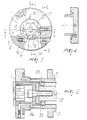
- the support for reel supporting shafts comprises a tubular outer part 30 which is fixed to a footing (not shown in the figure) inside which all the mechanical parts that constitute the actual support are arranged in a per se known manner.
- Such parts comprise an internal supporting ring 31 which can slide with respect to the tubular part 30, by virtue of an outer annular member 32, ensuring the axial adjustment of the support.
- Bearings 33 keyed inside the supporting ring 31, accommodate, in a per se known manner, a hollow rotating member 34 which provides the torque required to unwind or wind the reel.
- a connecting shaft 36 can slide inside the cavity 35, allowing in practice the advancement and retraction of the block 17 that closes a seat 2 of the end 4 of the reel supporting shaft 5 only when the opening of the seat 2 is directed upward, so that for safety reasons the end 4 of the reel supporting shaft 5 can be inserted or extracted exclusively from above.
- the mechanisms that allow this sliding and the connection among the various members are per se known.
- the actual support is constituted by a cavity which is open upward and is formed in an end of the rotating member 3 and which constitutes the seat 2 for an end 4 of the reel supporting shaft 5.
- the seat 2 is a semicylindrical surface 6 on which there are axial grooves which form a corresponding number of channels 8 for the insertion of rod members 9.
- the rod members 9 protrude partially from the semicylindrical surface 6, forming protruding portions 10 which, together with the semicylindrical surface 6, form a splined profile 11.
- the protruding portions 10 constitute the teeth that enter the complementarily shaped hollows 12, three in the illustrated case, which are formed in the end 4 of the reel supporting shaft 5.
- the rotating member 3 transfers the rotary motion to the shaft 5 and ensures their mutual centering.
- the end 4 of the shaft 5, as shown in Figure 7, has, over this entire cross-section 13, a profile which is adapted to receive, regardless of its rotation, the protrusions 10 of the seat 2.
- the rod members 9 are cylindrical and their dimensions are such that they can be inserted in, and removed from, the channels 8 of the head of the seat 2; they are also identical and interchangeable.
- the cylinders 9 are locked in the channels 8 by a locking member 14 which when applied to the lower part of the seat 2 closes, as shown in Figure 5, the inlets of the channels 8.
- the locking member 14 is constituted by a semicircular ring which is fixed by means of screws 15 and is also adapted to ensure axial contact between the seat 2 and the end 4 of the reel supporting shaft 5.
- the semicircular ring 14 enters a smaller-diameter region 16 of the end 4 of the reel supporting shaft 5 when the shaft is inserted from above, so that the shaft can follow the support during axial movement for adjustment.
- the closure block 17 comprises a semicylindrical dome 18 having a diameter equal to the lower part and operates, in a per se known manner.
- Another advantage according to the invention is that the interchangeable cylindrical members, owing to their length, transmit a higher torque than conventional couplings between the support and the shaft.
- Another advantage according to the invention is that this type of coupling, by eliminating plays, allows quieter rotation of the support.
Landscapes
- Unwinding Webs (AREA)
- Replacement Of Web Rolls (AREA)
- Storage Of Web-Like Or Filamentary Materials (AREA)
- Addition Polymer Or Copolymer, Post-Treatments, Or Chemical Modifications (AREA)
- Rolling Contact Bearings (AREA)
- Rolls And Other Rotary Bodies (AREA)
Abstract
Description
Claims (9)
- A support for reel supporting shafts, comprising a seat which is open upward and is adapted to receive one end of a reel supporting shaft, characterized in that said seat has a semicylindrical surface with at least one discontinuity channel which is adapted to accommodate at least one portion of at least one rod member which has a protruding portion which, together with the semicylindrical surface of said seat, forms a splined profile of said seat which cooperates with a splined section formed in said end of said reel supporting shaft and is complementary to said splined profile, so as to transmit a driving torque.
- The support for reel supporting shafts according to claim 1, characterized in that at least three discontinuity channels are formed in said semicylindrical surface of said seat and contain at least three identical and interchangeable members of said rod member, forming a splined profile with three teeth.
- The support for reel supporting shafts according to claim 1, characterized in that said end of said reel supporting shaft has a cross-section with at least three hollows which are shaped complementarily to said profile and is adapted to be moved by said seat.
- The support for reel supporting shafts according to one or more of the preceding claims, characterized in that said three rod members are constituted by a corresponding number of identical and interchangeable cylindrical bodies.
- The support for reel supporting shafts according to one or more of the preceding claims, characterized in that said cylindrical bodies are inserted at their head in the lower part of said seat, so that they are completely contained within said discontinuity channels.
- The support for reel supporting shafts according to one or more of the preceding claims, characterized in that said cylindrical members are locked in said discontinuity channels by a semicircular member which can be fixed on the head in the lower part of said seat, closing the openings of said channels.
- The support for reel supporting shafts according to one or more of the preceding claims, characterized in that the closure of the upper part of said seat is ensured by a semicylindrical dome having the same diameter, which is adapted to retract in order to allow the insertion of said end of said reel supporting shaft only when said insertion is performed from above.
- The support for reel supporting shafts according to one or more of the preceding claims, characterized in that said circular member, by entering a groove of said end of said reel supporting shafts, ensures that any axial adjustment movement of said support is followed by said shaft.
- The support for reel supporting shafts according to one or more of the preceding claims, characterized in that said protrusion of said reel supporting shaft has, on the entire perimeter of the cross-section, a profile with hollows which are complementarily shaped with respect to said profile.
Applications Claiming Priority (2)
| Application Number | Priority Date | Filing Date | Title |
|---|---|---|---|
| ITVI000052 | 2000-03-24 | ||
| IT2000VI000052A IT1315301B1 (en) | 2000-03-24 | 2000-03-24 | SUPPORT FOR REEL HOLDER SHAFTS |
Publications (3)
| Publication Number | Publication Date |
|---|---|
| EP1149786A2 true EP1149786A2 (en) | 2001-10-31 |
| EP1149786A3 EP1149786A3 (en) | 2002-10-23 |
| EP1149786B1 EP1149786B1 (en) | 2006-05-31 |
Family
ID=11461199
Family Applications (1)
| Application Number | Title | Priority Date | Filing Date |
|---|---|---|---|
| EP01107142A Expired - Lifetime EP1149786B1 (en) | 2000-03-24 | 2001-03-22 | Support for reel shafts |
Country Status (5)
| Country | Link |
|---|---|
| EP (1) | EP1149786B1 (en) |
| AT (1) | ATE327956T1 (en) |
| DE (1) | DE60120033D1 (en) |
| ES (1) | ES2263527T3 (en) |
| IT (1) | IT1315301B1 (en) |
Cited By (4)
| Publication number | Priority date | Publication date | Assignee | Title |
|---|---|---|---|---|
| DE10157235A1 (en) * | 2001-11-22 | 2003-06-12 | Boschert Ludwig Masch | Coupling between winder bar and winding machine has coupling pin, closure piece, piston, bearing housing, carrier shaft and bearings |
| IT201600105872A1 (en) * | 2016-10-20 | 2018-04-20 | Tecnopool Srl | SUPPORT DEVICE TO SUPPORT AND MOVE A ROLLER COMPARED TO A UPRIGHT. |
| US10384898B2 (en) * | 2015-12-24 | 2019-08-20 | Shih-Hao Ray Yeh | Fixing apparatus and automatic system |
| IT202000008122A1 (en) * | 2020-04-16 | 2021-10-16 | Carlo Scaravella | DEVICE FOR SUPPORTING AND TIGHTENING THE SHAFT OF A COIL |
Family Cites Families (5)
| Publication number | Priority date | Publication date | Assignee | Title |
|---|---|---|---|---|
| DE1088338B (en) * | 1956-09-27 | 1960-09-01 | Stahlkontor Weser G M B H | Device for inserting the flattened ends of winding bars, especially for paper webs, into the receiving heads of rotatably mounted shaft stubs |
| DE2852510C2 (en) * | 1978-12-05 | 1983-10-27 | Kunz Maschinen- und Apparatebau GmbH, 7850 Lörrach | Device for coupling winding bars |
| DE7923201U1 (en) * | 1979-08-14 | 1979-11-08 | Kunz Masch App | DEVICE FOR COUPLING A COILING ROD OR DGL. WITH A DRIVE SHAFT |
| DE4008897A1 (en) * | 1990-03-20 | 1991-09-26 | Peter Maier | Sliding ring bearing for winding rod spigots - has shaft with recess closable by movable side ring |
| DE4137921A1 (en) * | 1991-11-18 | 1993-05-19 | Windmoeller & Hoelscher | DEVICE FOR COUPLING A REEL SHAFT PIN WITH A DRIVE SHAFT PIN |
-
2000
- 2000-03-24 IT IT2000VI000052A patent/IT1315301B1/en active
-
2001
- 2001-03-22 EP EP01107142A patent/EP1149786B1/en not_active Expired - Lifetime
- 2001-03-22 DE DE60120033T patent/DE60120033D1/en not_active Expired - Lifetime
- 2001-03-22 ES ES01107142T patent/ES2263527T3/en not_active Expired - Lifetime
- 2001-03-22 AT AT01107142T patent/ATE327956T1/en not_active IP Right Cessation
Cited By (6)
| Publication number | Priority date | Publication date | Assignee | Title |
|---|---|---|---|---|
| DE10157235A1 (en) * | 2001-11-22 | 2003-06-12 | Boschert Ludwig Masch | Coupling between winder bar and winding machine has coupling pin, closure piece, piston, bearing housing, carrier shaft and bearings |
| DE10157235B4 (en) * | 2001-11-22 | 2005-05-19 | Ludwig Boschert Maschinen- Und Apparatebau Gmbh & Co Kg | Device for coupling a winding rod with a driving shaft of a winding machine |
| US10384898B2 (en) * | 2015-12-24 | 2019-08-20 | Shih-Hao Ray Yeh | Fixing apparatus and automatic system |
| IT201600105872A1 (en) * | 2016-10-20 | 2018-04-20 | Tecnopool Srl | SUPPORT DEVICE TO SUPPORT AND MOVE A ROLLER COMPARED TO A UPRIGHT. |
| IT202000008122A1 (en) * | 2020-04-16 | 2021-10-16 | Carlo Scaravella | DEVICE FOR SUPPORTING AND TIGHTENING THE SHAFT OF A COIL |
| EP3896303A1 (en) * | 2020-04-16 | 2021-10-20 | Carlo Scaravella | A supporting and clamping device for the shaft of a reel |
Also Published As
| Publication number | Publication date |
|---|---|
| ITVI20000052A1 (en) | 2001-09-24 |
| EP1149786A3 (en) | 2002-10-23 |
| EP1149786B1 (en) | 2006-05-31 |
| DE60120033D1 (en) | 2006-07-06 |
| ATE327956T1 (en) | 2006-06-15 |
| ES2263527T3 (en) | 2006-12-16 |
| IT1315301B1 (en) | 2003-02-10 |
Similar Documents
| Publication | Publication Date | Title |
|---|---|---|
| US8513845B2 (en) | Adjustable tubular electric motor unit for roll-up elements such as blinds and similar items | |
| US7056076B2 (en) | Method of and apparatus for transferring rolls, and roll supply carriage | |
| EP1149786B1 (en) | Support for reel shafts | |
| CA1283518C (en) | Apparatus for manufacturing resin tube | |
| JPS5818529B2 (en) | Bearing devices for parts that are axially slidable and rotationally connectable to each other | |
| EP0951826A2 (en) | Spinning reel for fishing | |
| US20220041392A1 (en) | Support spindle for windable material coils | |
| CA2196541C (en) | Core chuck | |
| KR102110343B1 (en) | Ball screw drive | |
| CN204715914U (en) | The U-shaped coded lock of high strength | |
| US5494434A (en) | Injection molding mold for producing a fitting having an annular groove | |
| JP4278565B2 (en) | Bead forming method and apparatus | |
| ES2702770T3 (en) | Ring rolling device with axially fixed bearings | |
| EP3705432B1 (en) | Annular device with improved performance for shafts of winding machines | |
| CN104948022A (en) | High-strength U-type coded lock | |
| ITVI940158A1 (en) | QUICK RELEASE END SUPPORT PARTICULARLY FOR SPOOL-HOLDER AXES. | |
| US6361305B1 (en) | Rotary tablet press | |
| KR20040035737A (en) | Device for winding/unwinding metal strips in particular for steel bands | |
| GB2059540A (en) | Apparatus for Producing Axial Movement | |
| JPS5927822B2 (en) | cylinder lock | |
| KR102958843B1 (en) | Pipe groove processing device | |
| CN220119009U (en) | Hidden camera support | |
| KR200142433Y1 (en) | Camera improves viewfinder movement | |
| SU1419906A1 (en) | Device for forming annular groove in funnel of plastic tube | |
| JP2536153Y2 (en) | Coil insertion device |
Legal Events
| Date | Code | Title | Description |
|---|---|---|---|
| PUAI | Public reference made under article 153(3) epc to a published international application that has entered the european phase |
Free format text: ORIGINAL CODE: 0009012 |
|
| AK | Designated contracting states |
Kind code of ref document: A2 Designated state(s): AT BE CH CY DE DK ES FI FR GB GR IE IT LI LU MC NL PT SE TR |
|
| AX | Request for extension of the european patent |
Free format text: AL;LT;LV;MK;RO;SI |
|
| PUAL | Search report despatched |
Free format text: ORIGINAL CODE: 0009013 |
|
| AK | Designated contracting states |
Kind code of ref document: A3 Designated state(s): AT BE CH CY DE DK ES FI FR GB GR IE IT LI LU MC NL PT SE TR |
|
| AX | Request for extension of the european patent |
Free format text: AL;LT;LV;MK;RO;SI |
|
| RIC1 | Information provided on ipc code assigned before grant |
Free format text: 7B 65H 16/06 A, 7B 65H 16/10 B |
|
| 17P | Request for examination filed |
Effective date: 20030314 |
|
| AKX | Designation fees paid |
Designated state(s): AT BE CH CY DE DK ES FI FR GB GR IE IT LI LU MC NL PT SE TR |
|
| 17Q | First examination report despatched |
Effective date: 20050118 |
|
| GRAP | Despatch of communication of intention to grant a patent |
Free format text: ORIGINAL CODE: EPIDOSNIGR1 |
|
| GRAS | Grant fee paid |
Free format text: ORIGINAL CODE: EPIDOSNIGR3 |
|
| GRAA | (expected) grant |
Free format text: ORIGINAL CODE: 0009210 |
|
| AK | Designated contracting states |
Kind code of ref document: B1 Designated state(s): AT BE CH CY DE DK ES FI FR GB GR IE IT LI LU MC NL PT SE TR |
|
| PG25 | Lapsed in a contracting state [announced via postgrant information from national office to epo] |
Ref country code: IT Free format text: LAPSE BECAUSE OF FAILURE TO SUBMIT A TRANSLATION OF THE DESCRIPTION OR TO PAY THE FEE WITHIN THE PRESCRIBED TIME-LIMIT;WARNING: LAPSES OF ITALIAN PATENTS WITH EFFECTIVE DATE BEFORE 2007 MAY HAVE OCCURRED AT ANY TIME BEFORE 2007. THE CORRECT EFFECTIVE DATE MAY BE DIFFERENT FROM THE ONE RECORDED. Effective date: 20060531 Ref country code: CH Free format text: LAPSE BECAUSE OF FAILURE TO SUBMIT A TRANSLATION OF THE DESCRIPTION OR TO PAY THE FEE WITHIN THE PRESCRIBED TIME-LIMIT Effective date: 20060531 Ref country code: LI Free format text: LAPSE BECAUSE OF FAILURE TO SUBMIT A TRANSLATION OF THE DESCRIPTION OR TO PAY THE FEE WITHIN THE PRESCRIBED TIME-LIMIT Effective date: 20060531 Ref country code: NL Free format text: LAPSE BECAUSE OF FAILURE TO SUBMIT A TRANSLATION OF THE DESCRIPTION OR TO PAY THE FEE WITHIN THE PRESCRIBED TIME-LIMIT Effective date: 20060531 Ref country code: FI Free format text: LAPSE BECAUSE OF FAILURE TO SUBMIT A TRANSLATION OF THE DESCRIPTION OR TO PAY THE FEE WITHIN THE PRESCRIBED TIME-LIMIT Effective date: 20060531 Ref country code: BE Free format text: LAPSE BECAUSE OF FAILURE TO SUBMIT A TRANSLATION OF THE DESCRIPTION OR TO PAY THE FEE WITHIN THE PRESCRIBED TIME-LIMIT Effective date: 20060531 Ref country code: AT Free format text: LAPSE BECAUSE OF FAILURE TO SUBMIT A TRANSLATION OF THE DESCRIPTION OR TO PAY THE FEE WITHIN THE PRESCRIBED TIME-LIMIT Effective date: 20060531 |
|
| REG | Reference to a national code |
Ref country code: GB Ref legal event code: FG4D Ref country code: CH Ref legal event code: EP |
|
| REG | Reference to a national code |
Ref country code: IE Ref legal event code: FG4D |
|
| REF | Corresponds to: |
Ref document number: 60120033 Country of ref document: DE Date of ref document: 20060706 Kind code of ref document: P |
|
| PG25 | Lapsed in a contracting state [announced via postgrant information from national office to epo] |
Ref country code: DK Free format text: LAPSE BECAUSE OF FAILURE TO SUBMIT A TRANSLATION OF THE DESCRIPTION OR TO PAY THE FEE WITHIN THE PRESCRIBED TIME-LIMIT Effective date: 20060831 Ref country code: SE Free format text: LAPSE BECAUSE OF FAILURE TO SUBMIT A TRANSLATION OF THE DESCRIPTION OR TO PAY THE FEE WITHIN THE PRESCRIBED TIME-LIMIT Effective date: 20060831 |
|
| PG25 | Lapsed in a contracting state [announced via postgrant information from national office to epo] |
Ref country code: DE Free format text: LAPSE BECAUSE OF FAILURE TO SUBMIT A TRANSLATION OF THE DESCRIPTION OR TO PAY THE FEE WITHIN THE PRESCRIBED TIME-LIMIT Effective date: 20060901 |
|
| PG25 | Lapsed in a contracting state [announced via postgrant information from national office to epo] |
Ref country code: PT Free format text: LAPSE BECAUSE OF FAILURE TO SUBMIT A TRANSLATION OF THE DESCRIPTION OR TO PAY THE FEE WITHIN THE PRESCRIBED TIME-LIMIT Effective date: 20061031 |
|
| NLV1 | Nl: lapsed or annulled due to failure to fulfill the requirements of art. 29p and 29m of the patents act | ||
| REG | Reference to a national code |
Ref country code: CH Ref legal event code: PL |
|
| REG | Reference to a national code |
Ref country code: ES Ref legal event code: FG2A Ref document number: 2263527 Country of ref document: ES Kind code of ref document: T3 |
|
| PLBE | No opposition filed within time limit |
Free format text: ORIGINAL CODE: 0009261 |
|
| STAA | Information on the status of an ep patent application or granted ep patent |
Free format text: STATUS: NO OPPOSITION FILED WITHIN TIME LIMIT |
|
| EN | Fr: translation not filed | ||
| 26N | No opposition filed |
Effective date: 20070301 |
|
| GBPC | Gb: european patent ceased through non-payment of renewal fee |
Effective date: 20070322 |
|
| PG25 | Lapsed in a contracting state [announced via postgrant information from national office to epo] |
Ref country code: IE Free format text: LAPSE BECAUSE OF NON-PAYMENT OF DUE FEES Effective date: 20070322 Ref country code: MC Free format text: LAPSE BECAUSE OF NON-PAYMENT OF DUE FEES Effective date: 20070331 |
|
| PG25 | Lapsed in a contracting state [announced via postgrant information from national office to epo] |
Ref country code: GR Free format text: LAPSE BECAUSE OF FAILURE TO SUBMIT A TRANSLATION OF THE DESCRIPTION OR TO PAY THE FEE WITHIN THE PRESCRIBED TIME-LIMIT Effective date: 20060901 Ref country code: GB Free format text: LAPSE BECAUSE OF NON-PAYMENT OF DUE FEES Effective date: 20070322 Ref country code: FR Free format text: LAPSE BECAUSE OF FAILURE TO SUBMIT A TRANSLATION OF THE DESCRIPTION OR TO PAY THE FEE WITHIN THE PRESCRIBED TIME-LIMIT Effective date: 20070309 |
|
| PG25 | Lapsed in a contracting state [announced via postgrant information from national office to epo] |
Ref country code: FR Free format text: LAPSE BECAUSE OF FAILURE TO SUBMIT A TRANSLATION OF THE DESCRIPTION OR TO PAY THE FEE WITHIN THE PRESCRIBED TIME-LIMIT Effective date: 20060531 |
|
| PG25 | Lapsed in a contracting state [announced via postgrant information from national office to epo] |
Ref country code: CY Free format text: LAPSE BECAUSE OF FAILURE TO SUBMIT A TRANSLATION OF THE DESCRIPTION OR TO PAY THE FEE WITHIN THE PRESCRIBED TIME-LIMIT Effective date: 20060531 Ref country code: LU Free format text: LAPSE BECAUSE OF NON-PAYMENT OF DUE FEES Effective date: 20070322 |
|
| PG25 | Lapsed in a contracting state [announced via postgrant information from national office to epo] |
Ref country code: TR Free format text: LAPSE BECAUSE OF FAILURE TO SUBMIT A TRANSLATION OF THE DESCRIPTION OR TO PAY THE FEE WITHIN THE PRESCRIBED TIME-LIMIT Effective date: 20060531 |
|
| REG | Reference to a national code |
Ref country code: ES Ref legal event code: PC2A Owner name: S.T.C.M. S.R.L. Effective date: 20111031 |
|
| REG | Reference to a national code |
Ref country code: ES Ref legal event code: PC2A Owner name: STCM INTERNATIONAL S.U.R.L. Effective date: 20120621 |
|
| REG | Reference to a national code |
Ref country code: ES Ref legal event code: PC2A Owner name: DOUBLE E EUROPE S.R.L. Effective date: 20150420 |
|
| PGFP | Annual fee paid to national office [announced via postgrant information from national office to epo] |
Ref country code: IT Payment date: 20200217 Year of fee payment: 20 |
|
| PGFP | Annual fee paid to national office [announced via postgrant information from national office to epo] |
Ref country code: ES Payment date: 20200406 Year of fee payment: 20 |
|
| PG25 | Lapsed in a contracting state [announced via postgrant information from national office to epo] |
Ref country code: ES Free format text: LAPSE BECAUSE OF EXPIRATION OF PROTECTION Effective date: 20210323 |