EP1149754A2 - Controller for vehicle steering apparatus and method for detecting abnormality in the controller - Google Patents
Controller for vehicle steering apparatus and method for detecting abnormality in the controller Download PDFInfo
- Publication number
- EP1149754A2 EP1149754A2 EP01110243A EP01110243A EP1149754A2 EP 1149754 A2 EP1149754 A2 EP 1149754A2 EP 01110243 A EP01110243 A EP 01110243A EP 01110243 A EP01110243 A EP 01110243A EP 1149754 A2 EP1149754 A2 EP 1149754A2
- Authority
- EP
- European Patent Office
- Prior art keywords
- command value
- sub
- torque command
- auxiliary torque
- steering
- Prior art date
- Legal status (The legal status is an assumption and is not a legal conclusion. Google has not performed a legal analysis and makes no representation as to the accuracy of the status listed.)
- Granted
Links
Images



Classifications
-
- B—PERFORMING OPERATIONS; TRANSPORTING
- B62—LAND VEHICLES FOR TRAVELLING OTHERWISE THAN ON RAILS
- B62D—MOTOR VEHICLES; TRAILERS
- B62D5/00—Power-assisted or power-driven steering
- B62D5/04—Power-assisted or power-driven steering electrical, e.g. using an electric servo-motor connected to, or forming part of, the steering gear
- B62D5/0457—Power-assisted or power-driven steering electrical, e.g. using an electric servo-motor connected to, or forming part of, the steering gear characterised by control features of the drive means as such
- B62D5/0481—Power-assisted or power-driven steering electrical, e.g. using an electric servo-motor connected to, or forming part of, the steering gear characterised by control features of the drive means as such monitoring the steering system, e.g. failures
- B62D5/0493—Power-assisted or power-driven steering electrical, e.g. using an electric servo-motor connected to, or forming part of, the steering gear characterised by control features of the drive means as such monitoring the steering system, e.g. failures detecting processor errors, e.g. plausibility of steering direction
Definitions
- the present invention relates to a controller for a vehicle steering apparatus, and more particularly, to a controller of an electromotive power steering apparatus that generates auxiliary force used by a steering wheel to steer a vehicle, such as an automobile, with a motor.
- an engine control system includes a main microcomputer (hereafter referred to as main computer) and a sub-microcomputer (hereafter referred to as sub-computer) to make the control system failproof.
- the outputs of the computers are compared. When the outputs differ, it is determined that the computation processing system has failed.
- the failproof technology is applied to a controller of an electromotive power steering apparatus, which includes a sub-computer and a main computer for monitoring the sub-computer.
- the sub-computer performs the same computations as the main computer in synchronism with the control cycle of the main computer. Then, the sub-computer compares the computation results of the main computer with its own computation results to determine whether the main computer has an abnormality.
- the sub-computer To properly monitor the main computer, the sub-computer must perform computations in the same control cycle as the main computer. Thus, the sub-computer must have the same capability as the main computer. This increases the cost of the controller.
- the present invention provides a controller of a steering apparatus including a motor for generating auxiliary force applied to a steering wheel to steer a vehicle.
- the motor is controlled in accordance with an auxiliary torque command value.
- the controller includes a main computer for computing the auxiliary torque command value in a main control routine, which is repeated cyclically, based on steering torque generated by the steering wheel and velocity of the vehicle.
- a sub-computer computes a value equivalent to the auxiliary torque command value in a sub-control routine, which is repeated cyclically, based on the steering torque and the vehicle velocity. Each cycle of the sub-control routine is longer than each of the main control routine.
- a first comparison circuit compares the auxiliary torque command value with the steering torque in each cycle of the main control routine.
- a second comparison circuit compares the auxiliary torque command value and the equivalent value in each cycle of the sub-control routine.
- the present invention is a method for detecting an abnormality in a controller of a steering apparatus including a motor for generating auxiliary force applied to a steering wheel to steer a vehicle.
- the controller includes a main computer and a sub-computer.
- the method includes computing an auxiliary torque command value of the motor with the main computer in a main control routine, which is repeated cyclically, cycle based on steering torque generated by the steering wheel and velocity of the vehicle.
- the auxiliary torque command value indicates the direction of the auxiliary force generated by the motor, and the steering torque indicates the steering direction of the steering wheel.
- the method also includes controlling the motor in accordance with the auxiliary torque command value, and computing a value equivalent to the auxiliary torque command value with the sub-computer in a sub-control routine, which is repeated cyclically, based on the steering torque and the vehicle velocity. Each cycle of the sub-control routine is longer than each of the main control routine.
- the method further includes comparing the direction of the auxiliary torque command value with the direction of the steering torque in each cycle of the main control routine, comparing the auxiliary torque command value and the equivalent value in each cycle of the sub-control routine, generating a first abnormality notification signal when the direction of the auxiliary torque command value and the direction of the steering torque do not match, and generating a second abnormality notification signal when the auxiliary torque command value and the equivalent value do not match.
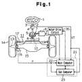
- Fig. 1 is a schematic view showing an electromotive power steering apparatus.
- a steering wheel 1 is connected to a steering shaft 2.
- a torsion bar 3 is arranged on the steering shaft 2.
- a torque sensor 4 is attached to the torsion bar 3. when the steering shaft 2 is rotated, a force is applied to the torsion bar 3, which is twisted in accordance with the force.
- the torque sensor 4 detects the steering torque T that is applied to the steering wheel 1 and outputs a voltage signal VT.
- a positive or negative code indicating the steering direction (rightward rotational direction or leftward rotational direction) of the steering shaft 2 is applied to the voltage signal VT.
- a reduction gear 5 is arranged on the steering shaft 2.
- a gear 7, which is arranged on a shaft of an electromotive motor 6, is meshed with the reduction gear 5.
- a pinion shaft 8 connects the reduction gear 5 to a rack and pinion mechanism 11.
- the rack and pinion mechanism 11 includes a pinion 9 and a rack 10, which is mated with the pinion 9.
- a tie rod 12 is connected to each of the two ends of the rack 10.
- a knuckle 13 is pivotally connected to the distal end of each tie rod 12.
- a front wheel 14 is mounted on each knuckle 13. The basal end of each knuckle 13 is pivotally connected to a cross member 15.
- the reduction gear 5 reduces the speed of the motor 6, or the rotating speed of the motor shaft.
- the pinion shaft 8 transmits the rotation of the motor shaft at the reduced speed to the rack and pinion mechanism 11 through the pinion shaft 8.
- the rack 10 accordingly changes the direction of the front wheels 14 by means of the tie rods 12.
- a vehicle velocity sensor 16 is provided for the front wheels 14 to generate a pulse signal corresponding to the vehicle velocity V.
- Fig. 2 is a block diagram illustrating the hardware configuration of a controller 21 of the electromotive power steering apparatus.
- the torque sensor 4 provides the controller 21 with a voltage signal VT, which corresponds with the steering torque T of the steering wheel 1.
- the vehicle velocity sensor 16 provides the controller 21 with a pulse signal P, which indicates the vehicle velocity V (i.e., the rotating speed of the front wheels 14).
- the controller 21 includes a main computer 22 and a sub-computer 23, each of which is a microcomputer.
- the main computer 22 includes a main CPU 24, a ROM 25, which stores various control programs, and a RAM 26, which is an operational memory.
- the sub-computer 23 includes a sub-CPU 27, a ROM 28, and a RAM 29.
- Fig. 3 is a schematic block diagram illustrating the software configuration of the controller 21,
- the main computer 22 includes a first target motor drive current computation circuit 221, a motor control circuit 222, a motor current detection circuit 223, and an abnormality detection circuit 224.
- the circuits 221, 222, 223, 224 function based on control programs.
- the first target motor drive current computation circuit 221 computes the steering torque T based on the voltage signal VT received from the torque sensor 4 and the vehicle velocity V based on the pulse signal P received from the vehicle velocity sensor 16. Further, the first target motor drive current computation circuit 221 computes a target drive current value (target current value), which serves as an auxiliary torque command value, based on the steering torque T.
- the target current value has a positive or negative code to indicate the drive direction of the shaft of the motor 6 (forward rotation direction or reverse rotation direction).
- the front wheels 14 are steered to the right when the motor shaft is rotated in the forward direction and steered to the left when the motor shaft is rotated in the reverse direction.
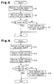
- the ROM 25 stores a high-speed basic current map, such as that shown in Fig. 4a, and a low-speed basic current map, such as that shown in Fig. 4b. Each current map is used to obtain the motor drive current value based on the steering torque T in accordance with the vehicle velocity V.
- the first target motor drive current computation circuit 221 obtains two motor drive current values corresponding to the steering torque T from the high speed basic current map and the low speed basic current map. Further, the first target motor drive current computation circuit 221 computes a target drive current corresponding to the vehicle velocity V by performing linear interpolation on the two motor drive current values based on the vehicle velocity V.
- the motor current detection circuit 223 detects the motor current of the motor 6 and sends a detection signal representing the motor current to the motor control circuit 222.
- the motor control circuit 222 compares the target current value computed by the first target motor drive current computation circuit 221 with the motor current value detected by the current detection circuit 223. Then, the motor control circuit 222 computes a motor current control value based on the comparison result. In other words, the motor control circuit 222 performs feedback control.
- the motor control circuit 222 generates a PWM signal having a duty ratio determined in accordance with the motor current control value. Further, the motor control circuit 222 includes a known PWM circuit (not shown) for generating a rotation direction signal, which determines the shaft rotating direction of the motor 6, based on the code of the motor current control value.
- a motor drive circuit 35 includes a known H-bridge circuit (not shown) having four electric field effect transistors. The transistors are activated and deactivated based on the PWM signal and the rotation direction signal output from the motor control circuit 222. This provides the motor 6 with a drive signal for rotating the motor shaft in the forward direction or the reverse direction. The motor 6 serves to generate auxiliary torque, which is added to the steering force.
- the abnormality detection circuit 224 In response to an abnormality notification signal from a target current comparison circuit 232 and a code determination circuit 233 (described later) of the sub-computer 23, the abnormality detection circuit 224 provides the motor control circuit 222 with a de-activation signal and stops the operation of the motor control circuit 222.
- the sub-computer 23 includes a second target motor drive current computation circuit 231, the target current comparison circuit 232, and the code determination circuit 233.
- the circuits 231, 232, 233 function in accordance with control programs.
- the second target motor drive current computation circuit 231 computes the steering torque T based on the voltage signal VT from the torque sensor 4 and computes the vehicle velocity v based on the pulse signal from the vehicle velocity sensor 16. Further, the second target motor drive current computation circuit 231 computes the target drive current (target current value), which serves as a second motor auxiliary torque command value, based on the steering torque T and the vehicle velocity V. The target current value is provided to the target current comparison circuit 232.
- the second target motor drive current computation circuit 231 is substantially identical to the first target motor drive current computation circuit 221. Thus, the target current value output from the second target motor drive current computation circuit 231 is equivalent to the target current value output from the first target motor drive current computation circuit 221.
- the two target current values match as long as the main and sub-computers 22, 23 function normally.
- the target current comparison circuit 232 receives the target current value of the main computer 22 from the first target motor drive current computation circuit 221 via a signal line and by means of serial communication. Further, the target current comparison circuit 232 receives the target current value of the sub-computer 23 from the second target motor drive current computation circuit 231. Then, the target current comparison circuit 232 compares the two target current values and determines that an abnormality occurred during the main computer target current value computation if the two target current values do not match. In this case, the target current comparison circuit 232 provides the abnormality detection circuit 224 with the abnormality notification signal.
- the sub-computer 23 is designed so that the computation cycle of the second target motor drive current computation circuit 231 and the comparison cycle (control cycle) of the target current comparison circuit 232 are longer than the computation cycle (control cycle) of the first target motor drive current computation circuit 221 of the main computer 22.
- the computation cycle of the main computer 22 is 1,000 Hz
- the computation cycle of the sub-computer 23 is 200 Hz.
- the second target motor drive current computation circuit 231 computes the target current value at a rate of once every predetermined number of times the first target motor drive current computation circuit 221 computes the target current value.
- the code determination circuit 233 receives the voltage signal VT, which corresponds with the steering torque T, from the torque sensor 4 and the target current value from the first target motor drive current computation circuit 221. Further, the code determination circuit 233 determines whether the code of the voltage signal VT matches the code of the target current value of the first target motor drive current computation circuit 221 in a cycle that is the same as the control cycles of the first target motor drive current computation circuit 221 and the motor control circuit 222. When the two codes match, the steering direction of the steering wheel 1 and the direction of the auxiliary force applied to the motor 6 are the same. When the two codes do not match, the steering direction of the steering wheel 1 and the direction of the auxiliary force applied to the motor 6 are not the same. Thus, the code determination circuit 233 determines that the computation of the target current value by the main computer 22 is abnormal and sends the abnormality notification signal to the abnormality detection circuit 224.
- Fig. 5 is flowchart of a code determination routine executed by the sub-computer 23. The execution of the code determination routine is repeated in every control cycle of the main CPU 24.
- step (hereafter simply referred to as S) 1 the sub-computer 23 stores the voltage signal VT of the torque sensor 4 in the RAM 29 (operational memory) when the vehicle is traveling.
- the code determination circuit 233 receives the target current value of the main computer 22 from the first target motor drive current computation circuit 221.
- the code determination circuit 233 determines whether the code of the voltage signal VT and the code of the target current value of the main computer 22 match. If the two codes match, the main computer 22 temporarily terminates the code determination routine. If the two codes do not match, the code determination circuit 233 proceeds to S4 and provides the abnormality detection circuit 224 of the main computer 22 with the abnormality notification signal, which indicates that the main computer 22 has an abnormality, and then temporarily terminates the code determination routine. Consequently, the abnormality detection circuit 224 provides the motor control circuit 222 with the deactivation signal in response to the abnormality notification signal and deactivates the motor control circuit 222.
- Fig. 6 is a flowchart illustrating a target current comparison routine executed by the sub-computer 23.
- the target current comparison routine is executed in every control cycle (i.e., every control cycle of the sub-computer 23), which is longer than the control cycle of the first target motor drive current computation circuit 221 in the main computer 22.
- the second target motor drive current computation circuit 231 receives the pulse signal from the vehicle velocity sensor 16 and the voltage signal VT from the torque sensor 4. At S12, the second target motor drive current computation circuit 231 computes the vehicle velocity V from the pulse signal and the steering torque T of the steering wheel 1 from the voltage signal VT. The second target motor drive current computation circuit 231 computes the target drive current value (target current value) of the sub-computer 23 based on the steering torque T and the vehicle velocity V. The computed target drive current is equivalent to the target drive current computed by the first target motor drive current computation circuit 221. Thus, the two target drive currents match when the main and sub-computers 22, 23 are functioning normally.
- the target current comparison circuit 232 receives the target current value of the main computer 22 from the first target motor drive current computation circuit 221 via a communication line.
- the target current value of the main computer 22 is the most recent value computed in the main computer 22.
- the target current comparison circuit 232 determines whether the target current value of the main computer 22 and the target current value of the sub-computer 23 match. If the two target current values match, the target current comparison circuit 232 temporarily terminates the target current comparison routine. If the two target current values do not match in S14, the target current comparison circuit 232 proceeds to S15 and provides the abnormality detection circuit 224 of the main computer 22 with the abnormality notification signal. The target current comparison circuit 232 then temporarily terminates the target current comparison routine.
- the abnormality detection circuit 224 provides the motor control circuit 222 with the de-activation signal in response to the abnormality notification signal and stops the operation of the motor control circuit 222.
- the abnormality detection circuit 224 stops the operation of the motor control circuit 222.
- the abnormality detection circuit 224 or the motor control circuit 222 may also be abnormal. Therefore, the operation of the motor 6 may be stopped by providing the motor drive circuit 35 with the abnormality detection signal from the target current comparison circuit 232 or the code determination circuit 233, as shown by the broken line in Fig. 3.
- the electromotive power steering apparatus controller 21 has the advantages discussed below.
- the controller 21 includes the main computer 22 and the sub-computer 23.
- the main computer 22 computes in every control cycle the target current value (auxiliary torque command value) based on the steering torque T of the steering wheel 1 and the vehicle velocity V.
- the sub-computer 23 computes in every control cycle, which is longer than the control cycle of the main computer 22, the target current value (equivalent to the auxiliary torque command value) based on the torque of the steering wheel 1 and the vehicle velocity V.
- the sub-computer 23 includes the code determination circuit 233 (first comparison circuit) and the target current comparison circuit 232 (second comparison circuit).
- the code determination circuit 233 compares the code of the target current value of the main computer 22 with the code of the steering torque T in synchronism with the control cycle of the main computer 22.
- the target current comparison circuit 232 compares the target current value of the main computer 22 with the target current value computed by the second target motor drive current computation circuit 231 in synchronism with the control cycle of the main computer 22.
- the sub-computer 23 does not compute the target current value in the same cycle as the main computer 22, the comparison of the code of the target current value, which is computed by the main computer 22, and the code of the steering torque T is synchronized with the control cycle of the main computer 22.
- the monitoring of the main computer 22 is ensured. This enables the employment of a sub-computer 23 having a capacity lower than the main computer 22 and decreases the cost of the controller 21.
- the comparison of the code of the target current value computed by the main computer 22 and the code of the voltage signal VT corresponding to the level of the steering torque T is performed in synchronism with the main computer 22.
- a code and level determination routine such as that illustrated in Fig. 7, may be performed in lieu of the code determination routine.
- the further embodiment performs the target current comparison routine of Fig. 6 and is applied to a controller having the same hardware configuration as the preferred embodiment.
- the processing performed in S10 is the same as that performed in S1 of Fig. 5.
- the processing performed in S20 is the same as that performed in S2 of Fig. 5.
- the code determination circuit 233 compares the code of the target current value of the main computer 22 with the code of the voltage signal VT, The code determination circuit 233 also determines whether the target current value is in an output toleration range based on a map, such as that shown in Fig. 8, Referring to Fig. 8, the output toleration range is the range in which the output of the target current value relative to the input voltage signal VT (steering torque T) is tolerated, and the output toleration range is obtained beforehand through experiments.
- the output toleration range set to eliminate target current values that are abnormally large and does not correspond with the input voltage signal VT (steering torque T).
- the code determination circuit 233 corresponds to a first comparison circuit, which determines whether the level of the main computer target current value (auxiliary torque command value) is in the output toleration range.
- the comparison of S30 is relatively simple. Thus, even if the sub-computer 23 does not compute the target current value in the same cycle as the main computer 22, the sub-computer 23 monitors the main computer 22. This enables the employment of a sub-computer 23 having a lower capacity than the main computer 22 and decreases the cost of the controller 21.
- the code determination circuit 233 may compute the steering torque T based on the voltage signal VT and perform determinations based on the code of the steering torque T.
- a vehicle steering apparatus controller (21) that enables a sub-computer (23) having a capacity lower than that of a main computer (22) to recognize computation results in the same control cycle as the main computer.
- the main computer of the controller computes an auxiliary torque command value of a steering motor based on the torque of a steering wheel and the velocity of the vehicle in a main control routine.
- the sub-computer of the controller computes a value equivalent to the command value based on the torque and the vehicle velocity in each cycle of a sub-control routine, which is longer than that of the main control routine.
- the sub-computer includes a first comparison circuit (233) for comparing the command value and the torque in each cycle of the main control routine and a second comparison circuit (232) for comparing the command value and the equivalent value in each cycle of the sub-control routine.
Landscapes
- Engineering & Computer Science (AREA)
- Chemical & Material Sciences (AREA)
- Combustion & Propulsion (AREA)
- Transportation (AREA)
- Mechanical Engineering (AREA)
- Steering Control In Accordance With Driving Conditions (AREA)
- Power Steering Mechanism (AREA)
Abstract
Description
Claims (13)
- A controller (21) of a steering apparatus including a motor (6) for generating auxiliary force applied to a steering wheel (1) to steer a vehicle, wherein the motor is controlled in accordance with an auxiliary torque command value, the controller comprising a main computer (22) for computing the auxiliary torque command value in a main control routine, which is repeated cyclically, based on steering torque generated by the steering wheel and velocity of the vehicle, and a sub-computer (23) for computing a value equivalent to the auxiliary torque command value in a sub-control routine, which is repeated cyclically, based on the steering torque and the vehicle velocity, wherein each cycle of the sub-control routine is longer than each cycle of the main control routine, the controller characterized bya first comparison circuit (233) for comparing the auxiliary torque command value with the steering torque in each cycle of the main control routine; anda second comparison circuit (232) for comparing the auxiliary torque command value and the equivalent value in each cycle of the sub-control routine.
- The controller according to claim 1, characterized in that the auxiliary torque command value indicates the direction of the auxiliary force generated by the motor, and the steering torque indicates the steering direction of the steering wheel, wherein the first comparison circuit generates a first abnormality notification signal when the direction of the auxiliary torque command value and the direction of the steering torque do not match, and wherein the second comparison circuit generates a second abnormality notification signal when the auxiliary torque command value and the equivalent value do not match.
- A controller (21) of a steering apparatus including a motor (6) for generating auxiliary force applied to a steering wheel (1) to steer a vehicle, wherein the motor is controlled in accordance with an auxiliary torque command value, the controller comprising a main computer (22) for computing the auxiliary torque command value in a main control routine, which is repeated cyclically, based on steering torque generated by the steering wheel and velocity of the vehicle, and a sub-computer (23) for computing a value equivalent to the auxiliary torque command value in a sub-control routine, which is repeated cyclically, based on the steering torque and the vehicle velocity, wherein each cycle of the sub-control routine is longer than each cycle of the main control routine, the controller characterized bya first comparison circuit (233) for determining whether the auxiliary torque command value is in a predetermined auxiliary torque toleration range in each cycle of the main control routine; anda second comparison circuit (232) for comparing the auxiliary torque command value and the equivalent value in each cycle of the sub-control routine.
- The controller according to claim 3, characterized in that the auxiliary torque toleration range indicates the tolerated direction and level of the auxiliary torque relative to the steering torque.
- The controller according to claim 4, characterized in that the first comparison circuit generates a first abnormality notification signal when the auxiliary torque command value is not in the toleration range, and wherein the second comparison circuit generates a second abnormality notification signal when the auxiliary torque command value and the equivalent value do not match.
- The controller according to claim 2 or 5, characterized in that the main computer includes an abnormality detection circuit (224) for generating a signal to stop the operation of the motor in response to at least one of the first and second abnormality notification signals.
- The controller according to one of claims 1 to 6, characterized in that the sub-computer includes at least one of the first and second comparison circuits.
- A method for detecting an abnormality in a controller (21) of a steering apparatus including a motor (6) for generating auxiliary force applied to a steering wheel (1) to steer a vehicle, wherein the controller includes a main computer (22) and a sub-computer (23), the method comprising the steps of computing an auxiliary torque command value of the motor with the main computer (22) in a main control routine, which is repeated cyclically, based on steering torque generated by the steering wheel and velocity of the vehicle, wherein the auxiliary torque command value indicates the direction of the auxiliary force generated by the motor, and the steering torque indicates the steering direction of the steering wheel; controlling the motor in accordance with the auxiliary torque command value; and computing a value equivalent to the auxiliary torque command value with the sub-computer (23) in a sub-control routine, which is repeated cyclically, based on the steering torque and the vehicle velocity, wherein each cycle of the sub-control cycle is longer than each cycle of the main control cycle, the method characterized by the steps of:comparing the direction of the auxiliary torque command value with the direction of the steering torque in each cycle of the main control routine;comparing the auxiliary torque command value and the equivalent value in each cycle of the sub-control routine;generating a first abnormality notification signal when the direction of the auxiliary torque command value and the direction of the steering torque do not match; andgenerating a second abnormality notification signal when the auxiliary torque command value and the equivalent value do not match.
- The method according to claim 8, characterized in that the sub-computer (23) performs at least one of the step of comparing the direction of the auxiliary torque command value direction and the steering torque direction and the step of comparing the auxiliary torque command value and the equivalent value.
- A method for detecting an abnormality in a controller (21) of a steering apparatus including a motor (6) for generating auxiliary force applied to a steering wheel (1) to steer a vehicle, wherein the controller includes a main computer (22) and a sub-computer (23), the method comprising the steps of computing an auxiliary torque command value of the motor with the main computer (22) in a main control routine, which is repeated cyclically, based on steering torque generated by the steering wheel and velocity of the vehicle, wherein the auxiliary torque command value indicates the direction of the auxiliary force generated by the motor; computing a value equivalent to the auxiliary torque command value with the sub-computer (23) in a sub-control routine, which is repeated cyclically, based on the steering torque and the vehicle velocity, wherein each cycle of the sub-control cycle is longer than each cycle of the main control cycle; and determining whether the auxiliary torque command value is in a predetermined auxiliary torque toleration range in each cycle of the main control routine, the method characterized by the steps of;comparing the auxiliary torque command value and the equivalent value in each cycle of the sub-control routine;generating a first abnormality notification signal when the auxiliary torque command value is not in the toleration range; andgenerating a second abnormality notification signal when the auxiliary torque command value and the equivalent value do not match.
- The controller according to claim 10, characterized in that the auxiliary torque toleration range indicates the tolerated direction and level of the auxiliary torque relative to the steering torque.
- The method according to claim 10 or 11, characterized in that the sub-computer (23) performs at least one of the step of determining whether the auxiliary torque command value is in the toleration range and the step of comparing the auxiliary torque command value and the equivalent value.
- The method according to one of claims 8 to 12, characterized by the step of:
generating a signal for stopping the operation of the motor in response to at least one of the first and second abnormality notification signals.
Applications Claiming Priority (2)
| Application Number | Priority Date | Filing Date | Title |
|---|---|---|---|
| JP2000125661A JP3777398B2 (en) | 2000-04-26 | 2000-04-26 | Vehicle steering control device |
| JP2000125661 | 2000-04-26 |
Publications (3)
| Publication Number | Publication Date |
|---|---|
| EP1149754A2 true EP1149754A2 (en) | 2001-10-31 |
| EP1149754A3 EP1149754A3 (en) | 2003-02-05 |
| EP1149754B1 EP1149754B1 (en) | 2004-02-11 |
Family
ID=18635572
Family Applications (1)
| Application Number | Title | Priority Date | Filing Date |
|---|---|---|---|
| EP01110243A Expired - Lifetime EP1149754B1 (en) | 2000-04-26 | 2001-04-25 | Controller for vehicle steering apparatus and method for detecting abnormality in the controller |
Country Status (4)
| Country | Link |
|---|---|
| US (1) | US6704632B2 (en) |
| EP (1) | EP1149754B1 (en) |
| JP (1) | JP3777398B2 (en) |
| DE (1) | DE60101973T2 (en) |
Cited By (8)
| Publication number | Priority date | Publication date | Assignee | Title |
|---|---|---|---|---|
| EP1316494A1 (en) * | 2001-11-30 | 2003-06-04 | Trw Inc. | Method and apparatus for controlling steering feel with diagnostics |
| FR2837772A1 (en) * | 2002-03-27 | 2003-10-03 | Koyo Seiko Co | STEERING SYSTEM FOR A MOTOR VEHICLE. |
| EP1588924A2 (en) | 2004-04-20 | 2005-10-26 | Hitachi, Ltd. | Vehicle controller |
| FR2875208A1 (en) * | 2004-09-10 | 2006-03-17 | Mitsubishi Electric Corp | DIRECTION CONTROL APPARATUS |
| EP1728704A1 (en) * | 2005-05-30 | 2006-12-06 | Jtekt Corporation | Controller for electric power steering apparatus |
| US8825299B2 (en) | 2010-09-30 | 2014-09-02 | Mitsubishi Electric Corporation | Control system and electric power steering control device |
| CN104044632A (en) * | 2013-03-11 | 2014-09-17 | 操纵技术Ip控股公司 | Cross Check Strategy For Systematic Error Protection |
| EP2161831A4 (en) * | 2007-06-22 | 2016-01-20 | Mitsubishi Motors Corp | DEVICE FOR CONTROLLING AN ELECTRIC VEHICLE |
Families Citing this family (26)
| Publication number | Priority date | Publication date | Assignee | Title |
|---|---|---|---|---|
| US6760653B2 (en) * | 2001-05-15 | 2004-07-06 | Trw Inc. | Electric power assisted steering system having a single integrated circuit with two processors |
| JP4109238B2 (en) * | 2004-10-18 | 2008-07-02 | トヨタ自動車株式会社 | Vehicle control device |
| JP4821144B2 (en) * | 2005-03-14 | 2011-11-24 | 日本精工株式会社 | Control method and control apparatus for electric power steering apparatus |
| DE102005044629A1 (en) * | 2005-09-19 | 2007-03-22 | Infineon Technologies Ag | Electric motor controlling device for e.g. motor vehicle, has monitoring unit outputting error signals during malfunction of sensor, and safety unit producing alternative motor control signals for controlling motor in quiescent state |
| JP4294039B2 (en) * | 2006-06-23 | 2009-07-08 | 三菱電機株式会社 | Power steering device |
| JP5035744B2 (en) * | 2006-11-02 | 2012-09-26 | 日本精工株式会社 | Electric power steering control device and method |
| US8738219B2 (en) * | 2009-08-24 | 2014-05-27 | Robert Bosch Gmbh | Good checking for vehicle longitudinal acceleration sensor |
| US8935037B2 (en) * | 2009-08-24 | 2015-01-13 | Robert Bosch Gmbh | Good checking for vehicle steering angle sensor |
| US8754764B2 (en) | 2009-08-24 | 2014-06-17 | Robert Bosch Gmbh | Good checking for vehicle pressure sensor |
| US8401730B2 (en) * | 2009-08-24 | 2013-03-19 | Robert Bosch Llc | Good checking for vehicle lateral acceleration sensor |
| US8494708B2 (en) | 2009-08-24 | 2013-07-23 | Robert Bosch Gmbh | Good checking for vehicle yaw rate sensor |
| US8467929B2 (en) * | 2009-08-24 | 2013-06-18 | Robert Bosch Gmbh | Good checking for vehicle wheel speed sensors |
| JP5528168B2 (en) | 2010-03-26 | 2014-06-25 | Ntn株式会社 | Controller for electric vehicles |
| JP5223945B2 (en) * | 2011-05-10 | 2013-06-26 | 日本精工株式会社 | Control method and control apparatus for electric power steering apparatus |
| KR101203872B1 (en) | 2011-06-07 | 2012-11-22 | 대성전기공업 주식회사 | Error detection apparatus and method for dual microcontroller system |
| CN102933443B (en) * | 2011-06-07 | 2015-11-25 | 大星电机工业株式会社 | Error detection device and method for dual controller system |
| DE102011053580A1 (en) * | 2011-09-14 | 2013-03-14 | Zf Lenksysteme Gmbh | METHOD FOR OPERATING AN ELECTRIC AUXILIARY POWER STEERING |
| JP5924671B2 (en) * | 2012-04-04 | 2016-05-25 | 三菱電機株式会社 | Motor control device and electric power steering device |
| JP5793106B2 (en) * | 2012-04-26 | 2015-10-14 | 日立オートモティブシステムズステアリング株式会社 | Power steering device and control device for power steering device |
| US10816354B2 (en) | 2017-08-22 | 2020-10-27 | Tusimple, Inc. | Verification module system and method for motion-based lane detection with multiple sensors |
| US11009356B2 (en) | 2018-02-14 | 2021-05-18 | Tusimple, Inc. | Lane marking localization and fusion |
| US11009365B2 (en) | 2018-02-14 | 2021-05-18 | Tusimple, Inc. | Lane marking localization |
| US12270661B2 (en) | 2018-02-14 | 2025-04-08 | Tusimple, Inc. | Lane marking localization and fusion |
| US12341420B2 (en) | 2020-03-13 | 2025-06-24 | Hitachi Astemo, Ltd. | Electronic control device for power conversion, and power supply IC |
| JP2021147008A (en) * | 2020-03-23 | 2021-09-27 | 本田技研工業株式会社 | Vehicle control device |
| EP3893150A1 (en) | 2020-04-09 | 2021-10-13 | Tusimple, Inc. | Camera pose estimation techniques |
Family Cites Families (5)
| Publication number | Priority date | Publication date | Assignee | Title |
|---|---|---|---|---|
| US5504679A (en) * | 1993-02-15 | 1996-04-02 | Mitsubishi Denki Kabushiki Kaisha | Control apparatus for motor-driven power steering system of motor vehicle |
| JP3212215B2 (en) * | 1994-03-17 | 2001-09-25 | 三菱電機株式会社 | Electric power steering control device |
| JP3132299B2 (en) | 1994-09-01 | 2001-02-05 | 日産自動車株式会社 | Auxiliary steering angle control device for vehicles |
| US6054827A (en) * | 1997-01-23 | 2000-04-25 | Mitsubishi Denki Kabushiki Kaisha | Controller for motor-driven power steering |
| JP3257971B2 (en) * | 1997-09-12 | 2002-02-18 | 本田技研工業株式会社 | Electric power steering device |
-
2000
- 2000-04-26 JP JP2000125661A patent/JP3777398B2/en not_active Expired - Fee Related
-
2001
- 2001-04-25 US US09/841,597 patent/US6704632B2/en not_active Expired - Fee Related
- 2001-04-25 DE DE60101973T patent/DE60101973T2/en not_active Expired - Fee Related
- 2001-04-25 EP EP01110243A patent/EP1149754B1/en not_active Expired - Lifetime
Cited By (16)
| Publication number | Priority date | Publication date | Assignee | Title |
|---|---|---|---|---|
| EP1702831A1 (en) * | 2001-11-30 | 2006-09-20 | TRW Automotive U.S. LLC | Method and apparatus for controlling steering feel with diagnostics |
| EP1316494A1 (en) * | 2001-11-30 | 2003-06-04 | Trw Inc. | Method and apparatus for controlling steering feel with diagnostics |
| FR2837772A1 (en) * | 2002-03-27 | 2003-10-03 | Koyo Seiko Co | STEERING SYSTEM FOR A MOTOR VEHICLE. |
| US7376498B2 (en) | 2004-04-20 | 2008-05-20 | Hitachi, Ltd. | Vehicle controller |
| EP1588924A2 (en) | 2004-04-20 | 2005-10-26 | Hitachi, Ltd. | Vehicle controller |
| EP1588924A3 (en) * | 2004-04-20 | 2005-11-23 | Hitachi, Ltd. | Vehicle controller |
| FR2875208A1 (en) * | 2004-09-10 | 2006-03-17 | Mitsubishi Electric Corp | DIRECTION CONTROL APPARATUS |
| US7610133B2 (en) | 2005-05-30 | 2009-10-27 | Jtekt Corporation | Controller for electric power steering apparatus |
| EP1728704A1 (en) * | 2005-05-30 | 2006-12-06 | Jtekt Corporation | Controller for electric power steering apparatus |
| EP2161831A4 (en) * | 2007-06-22 | 2016-01-20 | Mitsubishi Motors Corp | DEVICE FOR CONTROLLING AN ELECTRIC VEHICLE |
| US8825299B2 (en) | 2010-09-30 | 2014-09-02 | Mitsubishi Electric Corporation | Control system and electric power steering control device |
| CN104044632A (en) * | 2013-03-11 | 2014-09-17 | 操纵技术Ip控股公司 | Cross Check Strategy For Systematic Error Protection |
| EP2778021A1 (en) * | 2013-03-11 | 2014-09-17 | Steering Solutions IP Holding Corporation | Cross check strategy for systematic error protection |
| US9114826B2 (en) | 2013-03-11 | 2015-08-25 | Steering Solutions Ip Holding Corporation | Cross check strategy for systematic error protection |
| EP3159243A1 (en) * | 2013-03-11 | 2017-04-26 | Steering Solutions IP Holding Corporation | Cross check strategy for systematic error protection |
| CN104044632B (en) * | 2013-03-11 | 2017-06-13 | 操纵技术Ip控股公司 | For the cross check strategy of systematic error protection |
Also Published As
| Publication number | Publication date |
|---|---|
| JP3777398B2 (en) | 2006-05-24 |
| US20010051845A1 (en) | 2001-12-13 |
| EP1149754A3 (en) | 2003-02-05 |
| US6704632B2 (en) | 2004-03-09 |
| DE60101973D1 (en) | 2004-03-18 |
| DE60101973T2 (en) | 2005-01-05 |
| EP1149754B1 (en) | 2004-02-11 |
| JP2001310743A (en) | 2001-11-06 |
Similar Documents
| Publication | Publication Date | Title |
|---|---|---|
| EP1149754B1 (en) | Controller for vehicle steering apparatus and method for detecting abnormality in the controller | |
| EP0536590B1 (en) | Electric power steering apparatus | |
| US5927430A (en) | Electric power steering apparatus | |
| EP2913247A2 (en) | Vehicle steering device, failure determination method for vehicle steering device, and control method for steering motor | |
| US20170151978A1 (en) | Vehicle Steering Device | |
| JPH10287265A (en) | Method and device for dampingly controlling electric power steering system when vehicle speed signal is lost | |
| JP3232032B2 (en) | Variable steering angle ratio steering device | |
| EP3196096B1 (en) | Electric power steering device | |
| JP3486749B2 (en) | Electric power steering device | |
| EP3875348B1 (en) | Steering control apparatus | |
| JP2006143151A (en) | Electric power steering device | |
| JP4075622B2 (en) | Control system for electric power steering device | |
| JP2004114755A (en) | Electric power steering device | |
| JP2004196128A (en) | Electric power steering device | |
| JP2004196127A (en) | Electric power steering device | |
| US12054192B2 (en) | Abnormality detection device | |
| JP3047050B2 (en) | Electric power steering device | |
| US20040187600A1 (en) | Method for determining whether or not wheels are locked | |
| JP3104507B2 (en) | Abnormality determination device in power steering device | |
| JP3024664B2 (en) | Electric motor driven four-wheel steering system | |
| JP2698914B2 (en) | Electric power steering device | |
| JP3003742B2 (en) | Electric motor driven four-wheel steering system | |
| JPH0285074A (en) | Four-wheel steering device for vehicle | |
| JPH06286625A (en) | Failure detecting device for electric power steering | |
| JP3024665B2 (en) | Electric motor driven four-wheel steering system |
Legal Events
| Date | Code | Title | Description |
|---|---|---|---|
| PUAI | Public reference made under article 153(3) epc to a published international application that has entered the european phase |
Free format text: ORIGINAL CODE: 0009012 |
|
| AK | Designated contracting states |
Kind code of ref document: A2 Designated state(s): AT BE CH CY DE DK ES FI FR GB GR IE IT LI LU MC NL PT SE TR |
|
| AX | Request for extension of the european patent |
Free format text: AL;LT;LV;MK;RO;SI |
|
| PUAL | Search report despatched |
Free format text: ORIGINAL CODE: 0009013 |
|
| AK | Designated contracting states |
Designated state(s): AT BE CH CY DE DK ES FI FR GB GR IE IT LI LU MC NL PT SE TR |
|
| AX | Request for extension of the european patent |
Extension state: AL LT LV MK RO SI |
|
| 17P | Request for examination filed |
Effective date: 20030410 |
|
| GRAP | Despatch of communication of intention to grant a patent |
Free format text: ORIGINAL CODE: EPIDOSNIGR1 |
|
| AKX | Designation fees paid |
Designated state(s): DE FR GB |
|
| GRAS | Grant fee paid |
Free format text: ORIGINAL CODE: EPIDOSNIGR3 |
|
| GRAA | (expected) grant |
Free format text: ORIGINAL CODE: 0009210 |
|
| AK | Designated contracting states |
Kind code of ref document: B1 Designated state(s): DE FR GB |
|
| REG | Reference to a national code |
Ref country code: GB Ref legal event code: FG4D |
|
| REG | Reference to a national code |
Ref country code: IE Ref legal event code: FG4D |
|
| REF | Corresponds to: |
Ref document number: 60101973 Country of ref document: DE Date of ref document: 20040318 Kind code of ref document: P |
|
| ET | Fr: translation filed | ||
| PLBE | No opposition filed within time limit |
Free format text: ORIGINAL CODE: 0009261 |
|
| STAA | Information on the status of an ep patent application or granted ep patent |
Free format text: STATUS: NO OPPOSITION FILED WITHIN TIME LIMIT |
|
| 26N | No opposition filed |
Effective date: 20041112 |
|
| REG | Reference to a national code |
Ref country code: IE Ref legal event code: MM4A |
|
| PGFP | Annual fee paid to national office [announced via postgrant information from national office to epo] |
Ref country code: DE Payment date: 20080502 Year of fee payment: 8 Ref country code: FR Payment date: 20080312 Year of fee payment: 8 |
|
| PGFP | Annual fee paid to national office [announced via postgrant information from national office to epo] |
Ref country code: GB Payment date: 20080430 Year of fee payment: 8 |
|
| GBPC | Gb: european patent ceased through non-payment of renewal fee |
Effective date: 20090425 |
|
| REG | Reference to a national code |
Ref country code: FR Ref legal event code: ST Effective date: 20091231 |
|
| PG25 | Lapsed in a contracting state [announced via postgrant information from national office to epo] |
Ref country code: DE Free format text: LAPSE BECAUSE OF NON-PAYMENT OF DUE FEES Effective date: 20091103 |
|
| PG25 | Lapsed in a contracting state [announced via postgrant information from national office to epo] |
Ref country code: GB Free format text: LAPSE BECAUSE OF NON-PAYMENT OF DUE FEES Effective date: 20090425 Ref country code: FR Free format text: LAPSE BECAUSE OF NON-PAYMENT OF DUE FEES Effective date: 20091222 |