EP1149647A1 - Thin metal strip producing device - Google Patents
Thin metal strip producing device Download PDFInfo
- Publication number
- EP1149647A1 EP1149647A1 EP00971762A EP00971762A EP1149647A1 EP 1149647 A1 EP1149647 A1 EP 1149647A1 EP 00971762 A EP00971762 A EP 00971762A EP 00971762 A EP00971762 A EP 00971762A EP 1149647 A1 EP1149647 A1 EP 1149647A1
- Authority
- EP
- European Patent Office
- Prior art keywords
- metal
- cooling
- manufacturing apparatus
- flakes
- nozzle
- Prior art date
- Legal status (The legal status is an assumption and is not a legal conclusion. Google has not performed a legal analysis and makes no representation as to the accuracy of the status listed.)
- Granted
Links
Images




Classifications
-
- B—PERFORMING OPERATIONS; TRANSPORTING
- B22—CASTING; POWDER METALLURGY
- B22D—CASTING OF METALS; CASTING OF OTHER SUBSTANCES BY THE SAME PROCESSES OR DEVICES
- B22D11/00—Continuous casting of metals, i.e. casting in indefinite lengths
- B22D11/06—Continuous casting of metals, i.e. casting in indefinite lengths into moulds with travelling walls, e.g. with rolls, plates, belts, caterpillars
- B22D11/0622—Continuous casting of metals, i.e. casting in indefinite lengths into moulds with travelling walls, e.g. with rolls, plates, belts, caterpillars formed by two casting wheels
-
- B—PERFORMING OPERATIONS; TRANSPORTING
- B22—CASTING; POWDER METALLURGY
- B22F—WORKING METALLIC POWDER; MANUFACTURE OF ARTICLES FROM METALLIC POWDER; MAKING METALLIC POWDER; APPARATUS OR DEVICES SPECIALLY ADAPTED FOR METALLIC POWDER
- B22F9/00—Making metallic powder or suspensions thereof
- B22F9/02—Making metallic powder or suspensions thereof using physical processes
- B22F9/06—Making metallic powder or suspensions thereof using physical processes starting from liquid material
- B22F9/08—Making metallic powder or suspensions thereof using physical processes starting from liquid material by casting, e.g. through sieves or in water, by atomising or spraying
- B22F9/10—Making metallic powder or suspensions thereof using physical processes starting from liquid material by casting, e.g. through sieves or in water, by atomising or spraying using centrifugal force
-
- B—PERFORMING OPERATIONS; TRANSPORTING
- B22—CASTING; POWDER METALLURGY
- B22D—CASTING OF METALS; CASTING OF OTHER SUBSTANCES BY THE SAME PROCESSES OR DEVICES
- B22D11/00—Continuous casting of metals, i.e. casting in indefinite lengths
- B22D11/06—Continuous casting of metals, i.e. casting in indefinite lengths into moulds with travelling walls, e.g. with rolls, plates, belts, caterpillars
- B22D11/0637—Accessories therefor
- B22D11/068—Accessories therefor for cooling the cast product during its passage through the mould surfaces
- B22D11/0682—Accessories therefor for cooling the cast product during its passage through the mould surfaces by cooling the casting wheel
-
- B—PERFORMING OPERATIONS; TRANSPORTING
- B22—CASTING; POWDER METALLURGY
- B22D—CASTING OF METALS; CASTING OF OTHER SUBSTANCES BY THE SAME PROCESSES OR DEVICES
- B22D27/00—Treating the metal in the mould while it is molten or ductile ; Pressure or vacuum casting
- B22D27/003—Treating the metal in the mould while it is molten or ductile ; Pressure or vacuum casting by using inert gases
-
- B—PERFORMING OPERATIONS; TRANSPORTING
- B22—CASTING; POWDER METALLURGY
- B22F—WORKING METALLIC POWDER; MANUFACTURE OF ARTICLES FROM METALLIC POWDER; MAKING METALLIC POWDER; APPARATUS OR DEVICES SPECIALLY ADAPTED FOR METALLIC POWDER
- B22F1/00—Metallic powder; Treatment of metallic powder, e.g. to facilitate working or to improve properties
- B22F1/06—Metallic powder characterised by the shape of the particles
- B22F1/062—Fibrous particles
-
- B—PERFORMING OPERATIONS; TRANSPORTING
- B22—CASTING; POWDER METALLURGY
- B22F—WORKING METALLIC POWDER; MANUFACTURE OF ARTICLES FROM METALLIC POWDER; MAKING METALLIC POWDER; APPARATUS OR DEVICES SPECIALLY ADAPTED FOR METALLIC POWDER
- B22F9/00—Making metallic powder or suspensions thereof
- B22F9/02—Making metallic powder or suspensions thereof using physical processes
- B22F9/06—Making metallic powder or suspensions thereof using physical processes starting from liquid material
- B22F9/08—Making metallic powder or suspensions thereof using physical processes starting from liquid material by casting, e.g. through sieves or in water, by atomising or spraying
- B22F9/082—Making metallic powder or suspensions thereof using physical processes starting from liquid material by casting, e.g. through sieves or in water, by atomising or spraying atomising using a fluid
- B22F2009/086—Cooling after atomisation
-
- B—PERFORMING OPERATIONS; TRANSPORTING
- B22—CASTING; POWDER METALLURGY
- B22F—WORKING METALLIC POWDER; MANUFACTURE OF ARTICLES FROM METALLIC POWDER; MAKING METALLIC POWDER; APPARATUS OR DEVICES SPECIALLY ADAPTED FOR METALLIC POWDER
- B22F9/00—Making metallic powder or suspensions thereof
- B22F9/02—Making metallic powder or suspensions thereof using physical processes
- B22F9/06—Making metallic powder or suspensions thereof using physical processes starting from liquid material
- B22F9/08—Making metallic powder or suspensions thereof using physical processes starting from liquid material by casting, e.g. through sieves or in water, by atomising or spraying
- B22F9/082—Making metallic powder or suspensions thereof using physical processes starting from liquid material by casting, e.g. through sieves or in water, by atomising or spraying atomising using a fluid
- B22F2009/0896—Making metallic powder or suspensions thereof using physical processes starting from liquid material by casting, e.g. through sieves or in water, by atomising or spraying atomising using a fluid particle transport, separation: process and apparatus
Definitions
- the present invention relates to a metal-flake manufacturing apparatus which can simply and efficiently manufacture quenched metal-flake materials required for manufacture of thermoelectric materials, magnet materials, hydrogen absorbing alloys or the like.
- Thermoelectric materials, magnet materials, hydrogen absorbing alloys or the like which may be often intermetallic compounds, may be produced by crushing ingots. Conceived as an alternative way aimed at effective improvement of performances is to use quenched metal-flake materials, which way utilizes, as quench effects, compositional uniformity and crystal orientation along a quenching direction.
- Such metal flakes are produced by preliminarily producing a continuous, wide-width thin strip and then crushing or shearing this continuous thin strip. Mainly used to produce such continuous thin strip is a single or double roll method.
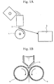
- molten metal is ejected from a nozzle 2 arranged above a cooling roll 1 to stably keep a molten metal reservoir (puddle), using surface tension of the molten metal, on a top of the cooling roll 1 which contacts the molten metal, thereby producing a continuous, wide-width thin strip which is received in a storage box 3.
- the single roll method has a problem that the molten metal reservoir (puddle) is difficult to stably keep at the top of the cooling roll 1. If the molten metal is excessively ejected, the molten metal reservoir may become unstable and drop sideways or backward of the cooling roll 1 or get mixed with the thin strip product to thereby lower the uniformity of the finished product.
- the cooling rolls 4 are used not only for cooling and solidification operations but also for rolling-down operation so that a large drive power is required for the cooling rolls 4 and the cooling rolls 4 tend to be severely damaged.
- the present invention was made in view of the above problems of the prior art and has its object to provide a metal-flake manufacturing apparatus which can overcome the problem on stable supply of molten metal in the single roll method and the problem on roll-drive power in the double roll method and which can manufacture quenched metal-flake materials in a simple and highly efficient manner.
- the inventors have reviewed quenched metal materials required for manufacture of thermoelectric materials, magnet materials, hydrogen absorbing alloys or the like to find out that utilized as quench effects in a thin strip are compositional uniformity and crystal orientation along a quenching direction and that to provide a continuous thin strip is not always a requisite since the thin strip is sheared or crushed in a next step.
- the invention was completed on the basis of such findings.
- a plurality of cooling rolls are spaced to have a gap or gaps of a size greater than thickness of metal thin bodies to be produced.
- a nozzle is provided to eject molten metal onto a surface of such cooling roll.
- the first cooling roll quenches the molten metal from the nozzle into metal thin bodies.
- the produced metal thin bodies are hit into flakes while the excess molten metal is made into metal thin bodies.
- the cooling rolls are arranged at different heights so that the produced metal thin bodies are sequentially hit on the rolls, which increases chances of the produced metal thin bodies being hit on the cooling rolls and contributes to obtaining further finer flakes and changeability of the flake withdrawal direction.
- Rotational axes of the cooling rolls may be out of parallelism so that a flying direction of the metal thin bodies, which is on a plane perpendicular to the rotational axis, may be changed with increased freedom.
- the cooling rolls may be arranged to rotate at different peripheral velocities. Differentiation in peripheral velocity between the cooling rolls will contribute to controlling the thickness of the metal thin bodies produced; if the cooling rolls with the same diameter were driven to rotate at the same peripheral velocity, thinner and thicker metal flakes would be produced on the upstream and downstream rolls, respectively.
- cooling rolls may have different diameters so as to have different peripheral velocities, which will contribute, just like the above, to controlling the thickness of the metal thin bodies.
- the nozzle may have a plurality of nozzle openings along the axis of the cooling roll. Provision of the nozzle openings in the shape of, for example, slot or circle, along the axis of the roll will contribute to further effective production of metal flakes.
- the nozzle opening may have a sectional area of 0.78- 78 mm 2 . Even with the nozzle openings having the sectional area as large as of 28-78 mm 2 , which are unusually large as compared with those in the conventional production of metal flakes, thick metal flakes can be produced with higher efficiency.
- the shape of the nozzle openings are not limited to circle.
- the nozzle and the cooling rolls may be placed in atmospheric gas and windbreak members may be arranged to prevent the atmospheric gas from being swirled by the rotating cooling rolls. Manufacturing in the atmosphere such as inert gas will enhance the quality of the metal flakes produced. Prevention of the atmospheric gas from being swirled by the rotating cooling rolls will prevent the nozzle from being cooled and prevent the metal flakes from being scattered.
- gas from atmospheric gas supply nozzles may be directed to guide the metal flakes towards a storage box in which metal flakes are to be stored, which will prevent the metal flakes from being scattered and contribute to efficient collection of the metal flakes in the box.
- the storage box may have a cooler for cooling the collected metal flakes, which will contribute to further improvement of the metal flake cooling efficiency.
- Fig. 2 is a schematic diagram of an embodiment of the metal-flake manufacturing apparatus according to the invention with two cooling rolls.
- This metal-flake manufacturing apparatus 10 comprises two, hollow cooling rolls 11 and 12 which are internally cooled.
- the two cooling rolls 11 and 12 are arranged at different heights such that the second roll 12 downstream in the direction of supply of the molten metal has a rotational axis which is upwardly offset to that of the upstream, first cooling roll 11 and that the two cooling rolls 11 and 12 are spaced to have a gap of a size greater than thickness of metal thin bodies to be produced.
- the thickness of the produced metal thin bodies is substantially dependent upon cooling capability and rotational frequency of the cooling roll 11. If the thickness of the metal thin bodies is 50-60 ⁇ m, then the gap between the cooling rolls 11 and 12 is to be of the order of 3 mm.
- These cooling rolls 11 and 12 are driven to rotate in opposite directions such that flakes are moved from above to below intermediately between the cooling rolls 11 and 12. They are driven by a drive (not shown) to rotate, for example, at peripheral velocities of the order of 10-50 m/sec.
- a tundish 13 Arranged above the first cooling roll 11 are a tundish 13 and a nozzle 14. Molten metal fed to the tundish 13 is ejected via the nozzle 14 onto the first cooling roll 11.
- This nozzle 14 is arranged to eject the molten metal to a surface of the first cooling roll 11 at a point downstream of the top of the roll in the direction of its rotation, whereby the molten metal, even if excessively ejected, may be splashed not backwards but forward of the roll.
- the nozzle 14 may be disposed such that the molten metal is ejected to the surface of the first cooling roll 11 at a point angularly downstream of the top of the roll in the direction of its rotation by 45° or so in terms of center angle.
- the nozzle 14 may have one or more nozzle openings.
- the multiple openings may be arranged in parallel with the axis of the first cooling roll 11, which makes it possible to produce metal thin bodies in multiple streams; alternatively, a metal thin body with a large width may be produced, though it is not a requisite at all.
- the nozzle 14 is arranged with a distance from the surface of the first cooling roll 11. This distance is set to be larger than that between the conventional single roll and nozzle since it is not necessary to produce a wide and continuous strip.
- This nozzle 14 used has opening or openings which may be in the shape of circle or slot.
- their diameter is preferably no more than 3 mm and its sectional area, no more than about 7.1 mm 2 from the viewpoint of improving the yield of the produced metal flakes.
- those with the diameter of more than 3 mm and the sectional area of more than about 7.1 mm 2 are also allowable, in which case thicker metal flakes will result.
- nozzle opening shape is not limited to circular, provided that the stated sectional area is secured.
- the nozzle 14 is provided with a heater/heat retainer or the like, the molten metal is prevented from being solidified at the nozzle and thus a stable operation can be ensured.
- a storage box 15 to collect metal flakes which have been obtained by hitting the metal thin bodies, which has been solidified on the first cooling roll 11, onto the second cooling roll 12 into flakes as well as by cooling and solidifying the molten metal, which are not cooled and solidified on the first cooling roll 11 but are splashed, on the second cooling roll 12.
- a guide tube 16 is arranged between beneath the two cooling rolls 11 and 12 and the storage box 15, so that the metal flakes are collected in the storage box 15 without being scattered.
- This metal-flake manufacturing apparatus 10 is entirely enclosed in a sealed container 17, allowing the metal flakes to be produced in an atmospheric gas such as an inert gas.
- the sealed container 17 is partitioned into upper and lower sections by a preload wall 18 at a bottom of the tundish 13.
- Atmospheric gas supply nozzles 19 are disposed in the sealed container 17 below the rolls 11 and 12 such that the gas is ejected respectively from the nozzles to the flow of flakes produced by the rolls 11 and 12, whereby the produced metal flakes are cooled and can be guided to the storage box 15 using the flow of the inert gas.
- the injected inert gas is sucked by a blower (not shown) via a gas suction inlet on the storage box 15, is cooled by a heat exchanger 20 and then re-supplied via the atmospheric gas supply nozzles 19 for circulation.
- whirls are generated by the cooling rolls 11 and 12 as the atmospheric gas such as inert gas is swirled due to high-velocity rotation of the cooling rolls in the atmospheric gas.
- windbreak plates 21 are protruded from the preload walls 18 at the sides of the nozzle 14 toward the cooling rolls 11 and 12.
- a cleaning brush 22 in the form of roll is provided for each of the cooling rolls 11 and 12 in such a manner as to contact an outer periphery of each roll.
- metal molten in a smelter is fed to the tundish 13 and is ejected onto the first cooling roll 11 which is driven to rotate and is internally cooled.
- the molten metal as it contacts the surface of the first cooling roll 11, is substantially solidified into a thin strip which is hit on a surface of and is crushed by the second cooling roll 12.
- the molten metal which was not solidified on the first cooling roll 11 but splashed forward into smaller chunks is hit on a roll surface of and is cooled and solidified by the second cooling roll 12, whereby the respective chunks of the molten metal are turned into flakes.
- the metal thin bodies in the form of metal flakes thus obtained by the first and second cooling rolls 11 and 12 are further hit on the surface of and are further crushed into flakes by the first cooling roll 11, and are guided and withdrawn into the storage box 15 by the guide tube 16 as well as by the flow of the inert gas fed from the atmospheric gas supply nozzles 19.
- the metal thin bodies produced through the respective steps are efficiently cooled by the atmospheric gas during their travels from the first cooling roll 11 to the second cooling roll 12, from the second cooling roll 12 back to the first cooling roll 11 and finally to the storage box 15 via the guide tube 16. Also in the storage box 15, they are cooled by the circulated inert gas. Thus, the metal flakes are efficiently cooled.
- the cooling rolls 11 and 12 are arranged not in contact with each other and there is no need to roll down the solidified metal between the rolls.
- the cooling rolls 11 and 12 require less drive power than in the prior-art double roll method, which contributes to substantial decrease of damage on the rolls.
- the atmospheric gas can be supplied for production of metal flakes in an atmosphere of inert gas, which contributes to production of metal flakes of high quality. Whirls caused by the swirling of the atmospheric gas, if any, can be blocked by the windbreak plates 21, thereby preventing cooling of the nozzle 14 and scattering of the metal flakes.
- a crusher may be provided before the storage box 15 in this metal-flake manufacturing apparatus 10 for further crushing of the flakes.
- a cooler may be provided in or around the sealed container 17 so as to cool the metal flakes.
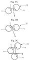
- the metal-flake manufacturing apparatus 10 has a plurality of cooling rolls the number and arrangement of which may be various; for example, as shown in Fig. 3A, two cooling rolls 11 and 12 may be used and arranged such that the metal thin bodies are first hit on the first cooling roll 11 and then on the second cooling roll 12 for withdrawal. Alternatively, as shown in Fig. 3B, the two rolls may be arranged such that the metal thin bodies are hit again on the first cooling roll 11 after its collision with the second cooling roll 12 before being withdrawn, thereby enhancing the crushing effects. Further alternatively, as shown in Fig. 3C, a third cooling roll 23 may be provided for further crushing of the metal flakes from the second cooling roll 12 as well as for change of the withdrawal direction into horizontal direction so as to suppress the overall height of the apparatus.
- Those metal-flake manufacturing apparatus 10 in which the number and arrangement of the cooling rolls are varied can also produce the metal flakes in a similar manner.
- the metal-flake manufacturing apparatus can stably produce the metal flakes even if the molten metal is ejected in larger quantity.
- the storage box can be of smaller size.
- the direction of collection of the metal flakes may be freely varied by varying the arrangement or number of the cooling rolls.
- the damage to and the rotative drive power required for the cooling rolls can be reduced as compared with the conventional double roll method.
- the metal flakes can be stably produced even if operational conditions such as shape of the nozzle may be varied in an extensive range, which is suitable for mass-production of metal flakes of constant quality.
- a metal-flake manufacturing apparatus 30 comprises a plurality of, for example two, cooling rolls 31 and 32 which have respectively rotational axes 31a and 32a not in parallel with each other.
- the second cooling roll 32 is disposed lower than and has its rotational axis 32a skew to the rotational axis 31a of the first cooling roll 31, which arrangement is to alter the direction of withdrawal of the metal flakes after being hit on the first cooling roll 31 and then on the second cooling roll 32, so as to attain for example compact in size of the apparatus.
- Such metal-flake manufacturing apparatus 30 with the rotational axes 31a and 32a of the cooling rolls 31 and 32 being not in parallel with each other can still produce the metal flakes in the same manner.
- the molten metal ejected onto the first cooling roll 31 is solidified upon contact with the surface of the first cooling roll 31 into a thin strip which flies along a plane 31b perpendicular to the rotational axis 31a and is hit on the surface of the second cooling roll 32.
- the metal thin strip having been solidified on the first cooling roll 31 is crushed into flakes while the splashed molten metal that failed to be solidified does contact the surface of the second cooling roll 32 to be cooled and solidified and turned into flakes, flying along a plane 32b perpendicular to the rotational axis 32a of the second cooling roll 32.
- the flying direction of the metal flakes may be adjusted by varying the arrangement of the rotational axes 31a and 32a of the cooling rolls 31 and 32, which enhances the degree of freedom in arranging the apparatus.
- the positioning of the cooling rolls is not limited to that in the above embodiment but may be chosen as desired depending upon a required flying direction. Also, the number of the cooling rolls is not limited to two and may be three or more so as to increase the degree of freedom in adjusting the flying direction.
- Figs. 5-7 show further embodiments of the metal-flake manufacturing apparatus according to the invention.
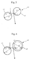
- Fig. 5 is a schematic diagram with the two cooling rolls having the same diameter;
- Fig. 6 is a schematic diagram with the two cooling rolls having different diameters;
- Fig. 7 shows a graph plotting the rotational velocity of the rolls against the average thickness of the metal flakes when the rolls have the same diameter.
- this metal-flake manufacturing apparatus 40 which has a plurality of, for example two, cooling rolls 41 and 42 adapted to have different peripheral velocities, which is achieved by, for example, differentiating rotational velocities v1 and v2 of the first and second cooling rolls 41 and 42 which have the same diameter as shown in Fig. 5; alternatively, the rolls may be driven to rotate at the same rotational frequency with, for example, the second cooling roll 43 being varied in diameter to have a varied peripheral velocity v3 as shown in Fig. 6.
- the thickness of the flakes manufactured by the first cooling roll decreases as the rotational velocity increases, as in the case of the single roll method.
- an average thickness of about 190 ⁇ m was measured with the rotation frequency of 500 rpm, and the average thickness was 100-120 ⁇ m when the rotation frequency was 800 rpm.
- mean thickness of the flakes produced by the second cooling roll is greater than that by the first cooling roll when the first and second cooling rolls had the same velocity.
- the average thickness was substantially constant at about 240 ⁇ m whether the rotation frequency was 500 rpm or 800 rpm.
- flakes produced by the second cooling roll are made from the molten metal which has a higher velocity than that on the first cooling roll, which will decrease a relative rotational velocity (peripheral velocity) of the second cooling roll, resulting in correspondingly thicker flakes.
- the average thickness of the flakes produced by' the second cooling roll may be decreased by increasing the rotation frequency of only the second cooling roll.
- the experiments revealed that flakes with substantially identical thickness can be obtained by setting the rotation frequencies of the first and second cooling rolls to be 800 rpm and 1150 rpm, respectively.
- the rotational velocity v1 of the first cooling roll 41 is differentiated from that v2 of the second cooling roll 42 when the rolls have the same diameter as shown in Fig. 5.
- the diameter d1 of the first cooling roll 41 is differentiated from that d3 of the second cooling roll 43 when the two rolls are rotated at the same rotation frequency, so that the latter has a different peripheral velocity v3 as shown in Fig. 6.
- the flakes produced by any of the cooling rolls 41, 42 or 43 have identical property, though the respective average thicknesses may be different.
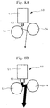
- Figs. 8A and 8B and 9 are sectional views of the nozzle portion and a graph plotting the nozzle diameter against the flake thickness in the further embodiments of the metal-flake manufacturing apparatus according to the invention.
- the metal-flake manufacturing apparatus 50 has a nozzle 51 with a nozzle opening 52 increased in size.
- Fig. 8B shows the nozzle 51 with a nozzle opening 52 further increased in size.
- the nozzle 14 when circular, had a diameter of 3 mm or less and a sectional area of 7.1 mm 2 ; however, here, used are the nozzle opening 52 with a diameter ranging from 1.0 to 10.0 mm and a sectional area ranging from 0.78 to 78 mm 2 , which are larger than the diameter of 3 mm or less and the sectional area of 7.1 mm 2 .
- the increase in diameter of the nozzle opening 52 results only in an increase in the average thickness of the produced metal flakes, and does not cause any problems in their property. They can be used as materials as they are.
- the nozzle opening diameter may be in the range from 6 to 10 mm and its sectional area from 28 to 78 mm 2 , which values are unusually large compared with those used in the conventional manufacture of the metal flakes. Still, there can be obtained metal flakes in a highly efficient manner.
- the resultant metal flakes have no problems in their property and can be used as materials as they are.
- the metal-flake manufacturing apparatus 50 may mass-produce thicker metal flakes efficiently by increasing the size of the nozzle opening 52 of the nozzle 51.
- the nozzle opening is not limited to circular in shape and may be shaped otherwise.
- the metal-flake manufacturing apparatus can manufacture metal flakes in a stable manner even when there is a large amount of molten metal ejected.
- the storage box can be of smaller size.
- the direction of collection of the metal flakes may be freely varied by varying the arrangement or number of the cooling rolls.
- the damage to and the rotative drive power required for the cooling rolls can be reduced as compared with the conventional double roll method.
- the metal flakes can be stably produced even if operational conditions such as shape of the nozzle may be varied in an extensive range, which is suitable for mass-production of metal flakes of constant quality.
- a plurality of cooling rolls are spaced to have a gap of a size greater than thickness of metal thin bodies to be produced.
- a nozzle is provided to eject molten metal onto a surface of such cooling roll.
- the first cooling roll quenches the molten metal from the nozzle into metal thin bodies.
- the produced metal thin bodies are hit into flakes while the excess molten metal is made into metal thin bodies.
- the cooling rolls are arranged at different heights so that the produced metal thin bodies are sequentially hit on the rolls, which increases chances of the produced metal thin bodies being hit on the cooling rolls and contributes to obtaining further finer flakes and changeability of the flake withdrawal direction.
- Rotational axes of the cooling rolls may be out of parallelism so that a flying direction of the metal thin bodies, which is on a plane perpendicular to the rotational axis, may be changed with increased freedom.
- the cooling rolls may be arranged to rotate at different peripheral velocities. Differentiation in peripheral velocity between the cooling rolls will contribute to controlling the thickness of the metal thin bodies produced; if the cooling rolls with the same diameter were driven to rotate at the same peripheral velocity, thinner and thicker metal flakes would be produced on the upstream and downstream rolls, respectively.
- cooling rolls may have different diameters so as to have different peripheral velocities, which will contribute, just like the above, to controlling the thickness of the metal thin bodies.
- the nozzle may have a plurality of nozzle openings along the axis of the cooling roll. Provision of the nozzle openings in the shape of, for example, slot or circle, along the axis of the roll will contribute to further effective production of metal flakes.
- the respective nozzle openings may have a sectional area of 0.78-78 mm 2 . Even with the nozzle openings having the sectional area as large as of 28-78 mm 2 , which are unusually large as compared with those in the conventional production of metal flakes, thick metal flakes can be produced with higher efficiency.
- the nozzle and the cooling rolls may be placed in atmospheric gas and windbreak members may be arranged to prevent the atmospheric gas from being swirled by the rotating cooling rolls. Manufacturing in the atmosphere such as inert gas will enhance the quality of the metal flakes produced. Prevention of the atmospheric gas from being swirled by the rotating cooling rolls will prevent the nozzle from being cooled and prevent the metal flakes from being scattered.
- gas from atmospheric gas supply nozzles may be directed to guide the metal flakes towards a storage box in which metal flakes are to be stored, which will prevent the metal flakes from being scattered and contribute to efficient collection of the metal flakes in the box.
- the storage box may have a cooler for cooling the collected metal flakes, which will contribute to further improvement of the metal flake cooling efficiency.
- the present invention provides a metal-flake manufacturing apparatus for manufacturing, in a simple and efficient manner, quenched metal-flake materials required for manufacture of thermoelectric materials, magnet materials, hydrogen storage alloys or the like.
Landscapes
- Engineering & Computer Science (AREA)
- Chemical & Material Sciences (AREA)
- Nanotechnology (AREA)
- Mechanical Engineering (AREA)
- Manufacture Of Metal Powder And Suspensions Thereof (AREA)
- Continuous Casting (AREA)
Abstract
Description
Claims (10)
- A metal-flake manufacturing apparatus, characterized in that a nozzle is arranged to eject molten metal on a cooling roll surface and cooling rolls, which quench molten metal from this nozzle into metal thin bodies and on which the produced metal thin bodies are hit into flakes, are arranged in plural numbers and are spaced to have a gap or gaps of a size greater than thickness of metal thin bodies.
- A metal-flake manufacturing apparatus according to claim 1, characterized in that said plurality of cooling rolls are arranged at different heights so that the produced metal thin bodies are sequentially hit on the rolls.
- A metal-flake manufacturing apparatus according to claim 1 or 2, characterized in that rotational axes of said cooling rolls are mutually out of parallelism.
- A metal-flake manufacturing apparatus according to any one of claims 1 to 3, characterized in that said cooling rolls are adapted to rotate at different peripheral velocities.
- A metal-flake manufacturing apparatus according to any one of claims 1 to 4, characterized in that said cooling rolls are adapted to have different roll diameters
- A metal-flake manufacturing apparatus according to any one of claims 1 to 5, characterized in that said nozzle has a plurality of nozzle openings along an axis of the cooling roll.
- A metal-flake manufacturing apparatus according to claim 6, characterized in that the nozzle openings of said nozzle have a sectional area of 0.78-78 mm2.
- A metal-flake manufacturing apparatus according to any one of claims 1 to 7, characterized in that said nozzle and said cooling rolls are placed in atmospheric gas and windbreak members are arranged to prevent the atmospheric gas from being swirled by the rotating cooling rolls.
- A metal-flake manufacturing apparatus according to claim 8, characterized in that gas from atmospheric gas supply nozzles for supplying said atmospheric gas is directed to guide the metal flakes toward a storage box in which metal flakes are to be stored.
- A metal-flake manufacturing apparatus according to claim 9, characterized in that said storage box has a cooler for cooling the metal flakes stored.
Applications Claiming Priority (5)
| Application Number | Priority Date | Filing Date | Title |
|---|---|---|---|
| JP31834099 | 1999-11-09 | ||
| JP31834099 | 1999-11-09 | ||
| JP2000251912A JP2002062043A (en) | 2000-08-23 | 2000-08-23 | Liquefied natural gas evaporative gas treatment equipment |
| JP2000000251 | 2000-08-23 | ||
| PCT/JP2000/007743 WO2001034326A1 (en) | 1999-11-09 | 2000-11-02 | Thin metal strip producing device |
Publications (3)
| Publication Number | Publication Date |
|---|---|
| EP1149647A1 true EP1149647A1 (en) | 2001-10-31 |
| EP1149647A4 EP1149647A4 (en) | 2006-07-19 |
| EP1149647B1 EP1149647B1 (en) | 2008-12-31 |
Family
ID=26569334
Family Applications (1)
| Application Number | Title | Priority Date | Filing Date |
|---|---|---|---|
| EP00971762A Expired - Lifetime EP1149647B1 (en) | 1999-11-09 | 2000-11-02 | Metal-flake manufacturing apparatus |
Country Status (7)
| Country | Link |
|---|---|
| US (1) | US6713017B1 (en) |
| EP (1) | EP1149647B1 (en) |
| KR (1) | KR100526646B1 (en) |
| CN (1) | CN1227083C (en) |
| CA (1) | CA2358909C (en) |
| DE (1) | DE60041245D1 (en) |
| WO (1) | WO2001034326A1 (en) |
Families Citing this family (24)
| Publication number | Priority date | Publication date | Assignee | Title |
|---|---|---|---|---|
| US6884269B2 (en) * | 2002-06-13 | 2005-04-26 | Fuelcell Energy, Inc. | Continuous method for manufacture of uniform size flake or powder |
| CN100540179C (en) * | 2004-09-20 | 2009-09-16 | 北京航空航天大学 | A method of rapid solidification to prepare amorphous thin strips |
| CN104252937B (en) * | 2014-09-12 | 2016-10-05 | 沈阳中北通磁科技股份有限公司 | A kind of regulate and control the sintered NdFeB permanent magnet ferrum of particulate combinations and manufacture method |
| CN104249156B (en) * | 2014-09-12 | 2017-08-08 | 沈阳中北通磁科技股份有限公司 | One kind is without bed material airflow milling powder method and Nd-Fe-B permanent magnet and its manufacture method |
| CN104226943B (en) * | 2014-09-12 | 2017-01-11 | 沈阳中北真空技术有限公司 | Vacuum melting rapid hardening equipment as well as manufacturing method of permanent magnet rapid hardening alloy and manufacturing method of permanent magnet |
| CN104227004A (en) * | 2014-09-12 | 2014-12-24 | 沈阳中北真空技术有限公司 | Jet-milling powder production facility without bed charge, jet-milling powder production method without bed charge and manufacturing method for permanent magnets |
| CN104226944B (en) * | 2014-09-12 | 2016-06-15 | 沈阳中北真空技术有限公司 | The manufacture method of two roller cooling vacuum melting rapid hardening equipment and permanent-magnet alloy, permanent magnet |
| CN104252938B (en) * | 2014-09-12 | 2016-10-05 | 沈阳中北通磁科技股份有限公司 | A kind of many principal phases Nd-Fe-B permanent magnet containing Ho and manufacture method |
| CN104226942B (en) * | 2014-09-12 | 2016-04-06 | 沈阳中北真空技术有限公司 | The manufacture method of two crucible vacuum melting rapid hardening equipment and permanent-magnet alloy, permanent magnet |
| CN104240886B (en) * | 2014-09-12 | 2017-01-11 | 沈阳中北通磁科技股份有限公司 | Tb-containing multi-main-phase neodymium iron boron permanent magnet and manufacturing method |
| CN104226941B (en) * | 2014-09-12 | 2016-10-05 | 沈阳中北真空技术有限公司 | With batch can vacuum melting rapid hardening equipment and permanent-magnet alloy and the manufacture method of permanent magnet |
| CN104240883B (en) * | 2014-09-12 | 2016-10-05 | 沈阳中北通磁科技股份有限公司 | RE permanent magnetic alloy sheet and dual alloy Nd-Fe-B permanent magnet and manufacture method thereof |
| CN104252940B (en) * | 2014-09-12 | 2016-10-05 | 沈阳中北通磁科技股份有限公司 | Nd-Fe-B permanent magnet that a kind of nitrogen content is low and manufacture method |
| CN104252939B (en) * | 2014-09-12 | 2016-10-05 | 沈阳中北通磁科技股份有限公司 | A kind of Nd-Fe-B permanent magnet with compound principal phase and manufacture method thereof |
| CN104240887B (en) * | 2014-09-12 | 2017-01-11 | 沈阳中北通磁科技股份有限公司 | Low-manganese-content neodymium-iron-boron permanent magnet and manufacturing method |
| CN105537600A (en) * | 2015-12-14 | 2016-05-04 | 韵升控股集团有限公司 | Preparation method for flaky powder |
| CN110087798B (en) * | 2016-12-26 | 2022-02-11 | 普锐特冶金技术日本有限公司 | Sealing method, sealing device, and continuous casting device provided with the same |
| CN109332718A (en) * | 2018-11-21 | 2019-02-15 | 孟静 | The fast preparation method of 3D printing alloy powder |
| CN109175393A (en) * | 2018-11-21 | 2019-01-11 | 孟静 | The quick preparation device of 3D printing alloy powder |
| CN113083944B (en) * | 2021-03-19 | 2024-05-28 | 福建省闽发铝业股份有限公司 | A method for preparing aluminum profile for side panel of battery box of new energy vehicle |
| CN113083945B (en) * | 2021-03-19 | 2024-05-28 | 福建省闽发铝业股份有限公司 | A method for preparing aluminum profile for end plate of battery box of new energy vehicle |
| CN114309505B (en) * | 2021-12-17 | 2023-01-10 | 北京科技大学 | A Metal Strip Continuous Casting Method Using Momentum Distribution |
| CN116099997B (en) * | 2022-01-28 | 2025-03-04 | 山东理工大学 | A crystallization roller movement method and device for double-roll thin strip process |
| CN117300078B (en) * | 2023-02-14 | 2026-04-24 | 山东理工大学 | A method for controlling the roll gap in a twin-roll thin strip process and a twin-roll thin strip casting machine device. |
Family Cites Families (11)
| Publication number | Priority date | Publication date | Assignee | Title |
|---|---|---|---|---|
| US4215084A (en) * | 1978-05-03 | 1980-07-29 | The Battelle Development Corporation | Method and apparatus for producing flake particles |
| JPS60261648A (en) | 1984-06-08 | 1985-12-24 | Mitsui Petrochem Ind Ltd | Apparatus for producing amorphous alloy |
| JPS6274007A (en) * | 1985-09-25 | 1987-04-04 | Alum Funmatsu Yakin Gijutsu Kenkyu Kumiai | Production of quickly cooled and solidified metallic flake |
| JPS63149053A (en) | 1986-07-01 | 1988-06-21 | Nippon Steel Corp | Production of metal or alloy strip having deformed sectional face |
| JPS6431559A (en) | 1987-07-25 | 1989-02-01 | Tokin Corp | Method and apparatus for producing rapidly cooled alloy strip from liquid and production of rare earth group magnet using rapidly cooled alloy strip from liquid |
| EP0284033B1 (en) * | 1987-03-23 | 1993-08-11 | Tokin Corporation | A method for producing a rare earth metal-iron-boron anisotropic bonded magnet from rapidly-quenched rare earth metal-iron-boron alloy ribbon-like flakes |
| JPS6418550A (en) | 1987-07-15 | 1989-01-23 | Nippon Yakin Kogyo Co Ltd | Production of direct casting strip |
| JPH01170553A (en) | 1987-12-25 | 1989-07-05 | Kawasaki Steel Corp | Device for manufacturing rapid cooling metal thin strip |
| JP3248942B2 (en) * | 1992-03-24 | 2002-01-21 | ティーディーケイ株式会社 | Cooling roll, method for manufacturing permanent magnet material, permanent magnet material, and permanent magnet material powder |
| JPH0847751A (en) | 1994-08-05 | 1996-02-20 | Nhk Spring Co Ltd | Method and device for manufacturing strip-shaped metallic foil |
| JP3373316B2 (en) | 1995-01-25 | 2003-02-04 | 新日本製鐵株式会社 | Winding method of rapidly solidified ribbon |
-
2000
- 2000-11-02 CA CA002358909A patent/CA2358909C/en not_active Expired - Lifetime
- 2000-11-02 US US09/868,905 patent/US6713017B1/en not_active Expired - Lifetime
- 2000-11-02 DE DE60041245T patent/DE60041245D1/en not_active Expired - Lifetime
- 2000-11-02 KR KR10-2001-7008588A patent/KR100526646B1/en not_active Expired - Lifetime
- 2000-11-02 EP EP00971762A patent/EP1149647B1/en not_active Expired - Lifetime
- 2000-11-02 WO PCT/JP2000/007743 patent/WO2001034326A1/en not_active Ceased
- 2000-11-02 CN CNB008026297A patent/CN1227083C/en not_active Expired - Lifetime
Also Published As
| Publication number | Publication date |
|---|---|
| CA2358909A1 (en) | 2001-05-17 |
| EP1149647A4 (en) | 2006-07-19 |
| CN1227083C (en) | 2005-11-16 |
| US6713017B1 (en) | 2004-03-30 |
| KR20010101403A (en) | 2001-11-14 |
| WO2001034326A1 (en) | 2001-05-17 |
| CA2358909C (en) | 2008-10-14 |
| CN1336855A (en) | 2002-02-20 |
| DE60041245D1 (en) | 2009-02-12 |
| KR100526646B1 (en) | 2005-11-08 |
| EP1149647B1 (en) | 2008-12-31 |
Similar Documents
| Publication | Publication Date | Title |
|---|---|---|
| CA2358909C (en) | Metal-flake manufacturing apparatus | |
| US7160398B2 (en) | Method of making rapidly solidified alloy for magnet | |
| US5993939A (en) | Method for preparing permanent magnet material, chill roll, permanent magnet material, and permanent magnet material powder | |
| KR101158327B1 (en) | Cooling device for cooling a metal strip | |
| JP3978794B2 (en) | Nozzle for introducing liquid metal into a continuous metal casting mold | |
| KR101942562B1 (en) | Apparatus and method for continuous manufacturing of metal chip | |
| CA2200470A1 (en) | Apparatus and method for the vertical casting of a metalbar | |
| JP3270713B2 (en) | Method and apparatus for producing metal powder | |
| CN113770367B (en) | Atomization equipment and atomization process for producing stainless steel shots | |
| EP0099599A1 (en) | Method of forming continuous strip of amorphous metal | |
| KR101942563B1 (en) | Apparatus and method for supplying molten iron of equipment for continuous manufacturing of metal chip | |
| JP2000117726A (en) | Wire saw | |
| JP4507367B2 (en) | Metal flake manufacturing equipment | |
| JP3526705B2 (en) | Continuous casting method for high carbon steel | |
| KR100527064B1 (en) | Injection nozzle and Method for manufacturing strip wire using it | |
| KR101945380B1 (en) | Cooling apparatus for mold of equipment for continuous manufacturing of metal chip | |
| JPH07102307A (en) | Flake powder material manufacturing method | |
| JP2002167611A (en) | Method and apparatus for producing metal flakes | |
| JP3843799B2 (en) | Metal flake manufacturing equipment | |
| JP7155045B2 (en) | METHOD AND APPARATUS FOR MANUFACTURING CONTINUOUS-CAST METAL RODS | |
| JPH0833915A (en) | Hot rolled steel sheet cooling equipment | |
| RU2245757C2 (en) | Secondary cooling zone apparatus | |
| JPS6345903B2 (en) | ||
| JPH0271505A (en) | Manufacture of permanent magnet flake | |
| JP2599177B2 (en) | Metal wire manufacturing equipment |
Legal Events
| Date | Code | Title | Description |
|---|---|---|---|
| PUAI | Public reference made under article 153(3) epc to a published international application that has entered the european phase |
Free format text: ORIGINAL CODE: 0009012 |
|
| 17P | Request for examination filed |
Effective date: 20010710 |
|
| AK | Designated contracting states |
Kind code of ref document: A1 Designated state(s): AT BE CH CY DE DK ES FI FR GB GR IE IT LI LU MC NL PT SE TR |
|
| AX | Request for extension of the european patent |
Free format text: AL;LT;LV;MK;RO;SI |
|
| RBV | Designated contracting states (corrected) |
Designated state(s): DE FR GB |
|
| A4 | Supplementary search report drawn up and despatched |
Effective date: 20060621 |
|
| RIC1 | Information provided on ipc code assigned before grant |
Ipc: B22F 1/00 20060101ALI20060615BHEP Ipc: B22F 9/10 20060101AFI20060615BHEP |
|
| 17Q | First examination report despatched |
Effective date: 20070711 |
|
| RAP1 | Party data changed (applicant data changed or rights of an application transferred) |
Owner name: IHI CORPORATION |
|
| RTI1 | Title (correction) |
Free format text: METAL-FLAKE MANUFACTURING APPARATUS |
|
| GRAP | Despatch of communication of intention to grant a patent |
Free format text: ORIGINAL CODE: EPIDOSNIGR1 |
|
| GRAS | Grant fee paid |
Free format text: ORIGINAL CODE: EPIDOSNIGR3 |
|
| GRAA | (expected) grant |
Free format text: ORIGINAL CODE: 0009210 |
|
| AK | Designated contracting states |
Kind code of ref document: B1 Designated state(s): DE FR GB |
|
| REG | Reference to a national code |
Ref country code: GB Ref legal event code: FG4D |
|
| REF | Corresponds to: |
Ref document number: 60041245 Country of ref document: DE Date of ref document: 20090212 Kind code of ref document: P |
|
| PLBE | No opposition filed within time limit |
Free format text: ORIGINAL CODE: 0009261 |
|
| STAA | Information on the status of an ep patent application or granted ep patent |
Free format text: STATUS: NO OPPOSITION FILED WITHIN TIME LIMIT |
|
| 26N | No opposition filed |
Effective date: 20091001 |
|
| REG | Reference to a national code |
Ref country code: FR Ref legal event code: PLFP Year of fee payment: 16 |
|
| REG | Reference to a national code |
Ref country code: FR Ref legal event code: PLFP Year of fee payment: 17 |
|
| REG | Reference to a national code |
Ref country code: FR Ref legal event code: PLFP Year of fee payment: 18 |
|
| REG | Reference to a national code |
Ref country code: FR Ref legal event code: PLFP Year of fee payment: 19 |
|
| PGFP | Annual fee paid to national office [announced via postgrant information from national office to epo] |
Ref country code: DE Payment date: 20191022 Year of fee payment: 20 |
|
| PGFP | Annual fee paid to national office [announced via postgrant information from national office to epo] |
Ref country code: FR Payment date: 20191014 Year of fee payment: 20 |
|
| PGFP | Annual fee paid to national office [announced via postgrant information from national office to epo] |
Ref country code: GB Payment date: 20191031 Year of fee payment: 20 |
|
| REG | Reference to a national code |
Ref country code: DE Ref legal event code: R071 Ref document number: 60041245 Country of ref document: DE |
|
| REG | Reference to a national code |
Ref country code: GB Ref legal event code: PE20 Expiry date: 20201101 |
|
| PG25 | Lapsed in a contracting state [announced via postgrant information from national office to epo] |
Ref country code: GB Free format text: LAPSE BECAUSE OF EXPIRATION OF PROTECTION Effective date: 20201101 |