EP1148740A2 - Magnetic tape recording apparatus and method, magnetic tape reproduction apparatus and method, and recording medium - Google Patents
Magnetic tape recording apparatus and method, magnetic tape reproduction apparatus and method, and recording medium Download PDFInfo
- Publication number
- EP1148740A2 EP1148740A2 EP01303002A EP01303002A EP1148740A2 EP 1148740 A2 EP1148740 A2 EP 1148740A2 EP 01303002 A EP01303002 A EP 01303002A EP 01303002 A EP01303002 A EP 01303002A EP 1148740 A2 EP1148740 A2 EP 1148740A2
- Authority
- EP
- European Patent Office
- Prior art keywords
- data
- video data
- magnetic tape
- rotating head
- magnetic
- Prior art date
- Legal status (The legal status is an assumption and is not a legal conclusion. Google has not performed a legal analysis and makes no representation as to the accuracy of the status listed.)
- Withdrawn
Links
Images






Classifications
-
- G—PHYSICS
- G11—INFORMATION STORAGE
- G11B—INFORMATION STORAGE BASED ON RELATIVE MOVEMENT BETWEEN RECORD CARRIER AND TRANSDUCER
- G11B20/00—Signal processing not specific to the method of recording or reproducing; Circuits therefor
- G11B20/10—Digital recording or reproducing
- G11B20/14—Digital recording or reproducing using self-clocking codes
- G11B20/1403—Digital recording or reproducing using self-clocking codes characterised by the use of two levels
- G11B20/1423—Code representation depending on subsequent bits, e.g. delay modulation, double density code, Miller code
- G11B20/1426—Code representation depending on subsequent bits, e.g. delay modulation, double density code, Miller code conversion to or from block codes or representations thereof
-
- G—PHYSICS
- G11—INFORMATION STORAGE
- G11B—INFORMATION STORAGE BASED ON RELATIVE MOVEMENT BETWEEN RECORD CARRIER AND TRANSDUCER
- G11B20/00—Signal processing not specific to the method of recording or reproducing; Circuits therefor
- G11B20/10—Digital recording or reproducing
-
- G—PHYSICS
- G11—INFORMATION STORAGE
- G11B—INFORMATION STORAGE BASED ON RELATIVE MOVEMENT BETWEEN RECORD CARRIER AND TRANSDUCER
- G11B20/00—Signal processing not specific to the method of recording or reproducing; Circuits therefor
- G11B20/10—Digital recording or reproducing
- G11B20/12—Formatting, e.g. arrangement of data block or words on the record carriers
- G11B20/1201—Formatting, e.g. arrangement of data block or words on the record carriers on tapes
- G11B20/1207—Formatting, e.g. arrangement of data block or words on the record carriers on tapes with transverse tracks only
-
- G—PHYSICS
- G11—INFORMATION STORAGE
- G11B—INFORMATION STORAGE BASED ON RELATIVE MOVEMENT BETWEEN RECORD CARRIER AND TRANSDUCER
- G11B20/00—Signal processing not specific to the method of recording or reproducing; Circuits therefor
- G11B20/10—Digital recording or reproducing
- G11B20/18—Error detection or correction; Testing, e.g. of drop-outs
- G11B20/1806—Pulse code modulation systems for audio signals
- G11B20/1809—Pulse code modulation systems for audio signals by interleaving
-
- G—PHYSICS
- G11—INFORMATION STORAGE
- G11B—INFORMATION STORAGE BASED ON RELATIVE MOVEMENT BETWEEN RECORD CARRIER AND TRANSDUCER
- G11B27/00—Editing; Indexing; Addressing; Timing or synchronising; Monitoring; Measuring tape travel
- G11B27/10—Indexing; Addressing; Timing or synchronising; Measuring tape travel
- G11B27/19—Indexing; Addressing; Timing or synchronising; Measuring tape travel by using information detectable on the record carrier
- G11B27/28—Indexing; Addressing; Timing or synchronising; Measuring tape travel by using information detectable on the record carrier by using information signals recorded by the same method as the main recording
- G11B27/30—Indexing; Addressing; Timing or synchronising; Measuring tape travel by using information detectable on the record carrier by using information signals recorded by the same method as the main recording on the same track as the main recording
- G11B27/3027—Indexing; Addressing; Timing or synchronising; Measuring tape travel by using information detectable on the record carrier by using information signals recorded by the same method as the main recording on the same track as the main recording used signal is digitally coded
-
- G—PHYSICS
- G11—INFORMATION STORAGE
- G11B—INFORMATION STORAGE BASED ON RELATIVE MOVEMENT BETWEEN RECORD CARRIER AND TRANSDUCER
- G11B27/00—Editing; Indexing; Addressing; Timing or synchronising; Monitoring; Measuring tape travel
- G11B27/10—Indexing; Addressing; Timing or synchronising; Measuring tape travel
- G11B27/19—Indexing; Addressing; Timing or synchronising; Measuring tape travel by using information detectable on the record carrier
- G11B27/28—Indexing; Addressing; Timing or synchronising; Measuring tape travel by using information detectable on the record carrier by using information signals recorded by the same method as the main recording
- G11B27/30—Indexing; Addressing; Timing or synchronising; Measuring tape travel by using information detectable on the record carrier by using information signals recorded by the same method as the main recording on the same track as the main recording
- G11B27/3027—Indexing; Addressing; Timing or synchronising; Measuring tape travel by using information detectable on the record carrier by using information signals recorded by the same method as the main recording on the same track as the main recording used signal is digitally coded
- G11B27/3063—Subcodes
-
- G—PHYSICS
- G11—INFORMATION STORAGE
- G11B—INFORMATION STORAGE BASED ON RELATIVE MOVEMENT BETWEEN RECORD CARRIER AND TRANSDUCER
- G11B5/00—Recording by magnetisation or demagnetisation of a record carrier; Reproducing by magnetic means; Record carriers therefor
- G11B5/008—Recording on, or reproducing or erasing from, magnetic tapes, sheets, e.g. cards, or wires
- G11B5/00813—Recording on, or reproducing or erasing from, magnetic tapes, sheets, e.g. cards, or wires magnetic tapes
- G11B5/00847—Recording on, or reproducing or erasing from, magnetic tapes, sheets, e.g. cards, or wires magnetic tapes on transverse tracks
- G11B5/0086—Recording on, or reproducing or erasing from, magnetic tapes, sheets, e.g. cards, or wires magnetic tapes on transverse tracks using cyclically driven heads providing segmented tracks
-
- G—PHYSICS
- G11—INFORMATION STORAGE
- G11B—INFORMATION STORAGE BASED ON RELATIVE MOVEMENT BETWEEN RECORD CARRIER AND TRANSDUCER
- G11B5/00—Recording by magnetisation or demagnetisation of a record carrier; Reproducing by magnetic means; Record carriers therefor
- G11B5/02—Recording, reproducing, or erasing methods; Read, write or erase circuits therefor
- G11B5/09—Digital recording
-
- H—ELECTRICITY
- H04—ELECTRIC COMMUNICATION TECHNIQUE
- H04N—PICTORIAL COMMUNICATION, e.g. TELEVISION
- H04N9/00—Details of colour television systems
- H04N9/79—Processing of colour television signals in connection with recording
- H04N9/80—Transformation of the television signal for recording, e.g. modulation, frequency changing; Inverse transformation for playback
- H04N9/804—Transformation of the television signal for recording, e.g. modulation, frequency changing; Inverse transformation for playback involving pulse code modulation of the colour picture signal components
- H04N9/8042—Transformation of the television signal for recording, e.g. modulation, frequency changing; Inverse transformation for playback involving pulse code modulation of the colour picture signal components involving data reduction
-
- G—PHYSICS
- G11—INFORMATION STORAGE
- G11B—INFORMATION STORAGE BASED ON RELATIVE MOVEMENT BETWEEN RECORD CARRIER AND TRANSDUCER
- G11B2220/00—Record carriers by type
- G11B2220/90—Tape-like record carriers
-
- G—PHYSICS
- G11—INFORMATION STORAGE
- G11B—INFORMATION STORAGE BASED ON RELATIVE MOVEMENT BETWEEN RECORD CARRIER AND TRANSDUCER
- G11B5/00—Recording by magnetisation or demagnetisation of a record carrier; Reproducing by magnetic means; Record carriers therefor
- G11B5/008—Recording on, or reproducing or erasing from, magnetic tapes, sheets, e.g. cards, or wires
- G11B5/00813—Recording on, or reproducing or erasing from, magnetic tapes, sheets, e.g. cards, or wires magnetic tapes
- G11B5/00878—Recording on, or reproducing or erasing from, magnetic tapes, sheets, e.g. cards, or wires magnetic tapes transducing different track configurations or formats on the same tape
-
- H—ELECTRICITY
- H04—ELECTRIC COMMUNICATION TECHNIQUE
- H04N—PICTORIAL COMMUNICATION, e.g. TELEVISION
- H04N5/00—Details of television systems
- H04N5/76—Television signal recording
- H04N5/78—Television signal recording using magnetic recording
- H04N5/782—Television signal recording using magnetic recording on tape
- H04N5/7824—Television signal recording using magnetic recording on tape with rotating magnetic heads
- H04N5/7826—Television signal recording using magnetic recording on tape with rotating magnetic heads involving helical scanning of the magnetic tape
- H04N5/78263—Television signal recording using magnetic recording on tape with rotating magnetic heads involving helical scanning of the magnetic tape for recording on tracks inclined relative to the direction of movement of the tape
-
- H—ELECTRICITY
- H04—ELECTRIC COMMUNICATION TECHNIQUE
- H04N—PICTORIAL COMMUNICATION, e.g. TELEVISION
- H04N9/00—Details of colour television systems
- H04N9/79—Processing of colour television signals in connection with recording
- H04N9/7921—Processing of colour television signals in connection with recording for more than one processing mode
-
- H—ELECTRICITY
- H04—ELECTRIC COMMUNICATION TECHNIQUE
- H04N—PICTORIAL COMMUNICATION, e.g. TELEVISION
- H04N9/00—Details of colour television systems
- H04N9/79—Processing of colour television signals in connection with recording
- H04N9/80—Transformation of the television signal for recording, e.g. modulation, frequency changing; Inverse transformation for playback
- H04N9/804—Transformation of the television signal for recording, e.g. modulation, frequency changing; Inverse transformation for playback involving pulse code modulation of the colour picture signal components
- H04N9/806—Transformation of the television signal for recording, e.g. modulation, frequency changing; Inverse transformation for playback involving pulse code modulation of the colour picture signal components with processing of the sound signal
- H04N9/8063—Transformation of the television signal for recording, e.g. modulation, frequency changing; Inverse transformation for playback involving pulse code modulation of the colour picture signal components with processing of the sound signal using time division multiplex of the PCM audio and PCM video signals
-
- H—ELECTRICITY
- H04—ELECTRIC COMMUNICATION TECHNIQUE
- H04N—PICTORIAL COMMUNICATION, e.g. TELEVISION
- H04N9/00—Details of colour television systems
- H04N9/79—Processing of colour television signals in connection with recording
- H04N9/80—Transformation of the television signal for recording, e.g. modulation, frequency changing; Inverse transformation for playback
- H04N9/82—Transformation of the television signal for recording, e.g. modulation, frequency changing; Inverse transformation for playback the individual colour picture signal components being recorded simultaneously only
- H04N9/8205—Transformation of the television signal for recording, e.g. modulation, frequency changing; Inverse transformation for playback the individual colour picture signal components being recorded simultaneously only involving the multiplexing of an additional signal and the colour video signal
Definitions
- Each track is F0, F1, or F2 according to the type of a pilot signal recorded therein for tracking control. Tracks are formed in the order of F0, F1, F0, F2, F0, F1, F0, and F2.
- one-unit video data is continuously arranged, and the corresponding audio data is also continuously arranged before the video data.
- audio data A n+2 , audio data A n , and audio data A n+1 corresponding to the I picture I n+2 , the B picture B n , and the B picture B n+1 are continuously arranged, and following them, the I picture I n+2 , the B picture B n , and the B picture B n+1 are continuously arranged.
Landscapes
- Engineering & Computer Science (AREA)
- Signal Processing (AREA)
- Multimedia (AREA)
- Signal Processing For Digital Recording And Reproducing (AREA)
- Television Signal Processing For Recording (AREA)
Abstract
A magnetic-tape recording apparatus records digital data on a magnetic tape (14) by a rotating head (12). It includes a first obtaining device (1) for obtaining predetermined-unit video data; a second obtaining device (2) for obtaining audio data corresponding to the predetermined-unit video data; a synthesizing device (4) for synthesizing the predetermined-unit video data and the audio data corresponding to the predetermined-unit video data such that they are continuous on a track in the magnetic tape (14) without any space disposed therebetween; and a sending device (5-11) for sending data synthesized by the synthesizing device (4) to the rotating head (12) in order to record the data on the magnetic tape (14). <IMAGE>
Description
The present invention relates to magnetic-tape
recording apparatus and methods of recording on magnetic-tape.
The present invention also relates to magnetic
reproducing apparatus and methods of reproducing from
magnetic tape. The present invention also relates to
recording media.
Compression technologies have been advancing these days.
Video data is compressed, for example, by a Digital Video
(DV) method and recorded into a magnetic tape.
To record high-quality video data (hereinafter called
high-definition (HD) video data), for example, a bit rate of
about 25 Mbps is required. In a conventional recording
method, the video rate corresponding to an MP@HL Moving
Picture Expert Group (MPEG) method is at most about 24 Mbps
except for the rate of search-image data. As a result,
standard-quality video data (hereinafter called standard-definition
(SD) video data) can be recorded, but it is
impossible to compress and record HD video data by the MP@HL
or an MP@H-14 method.
In addition, HD video data compressed by the MP@HL or
MP@H-14 method cannot be efficiently tied to that compressed
by the MP@HL or MP@H-14 method.
Various aspects and features of the present invention
are defined in the appended claims.
The present invention has been made in consideration of
the above conditions. Accordingly, embodiments of the
present invention allow HD video data to be recorded and
reproduced, and to be efficiently edited.
In one aspect of the present invention there is
provided a magnetic-tape
recording apparatus for recording digital data on a magnetic
tape by a rotating head, including first obtaining means for
obtaining predetermined-unit video data; second obtaining
means for obtaining audio data corresponding to the
predetermined-unit video data; synthesizing means for
synthesizing the predetermined-unit video data and the audio
data corresponding to the predetermined-unit video data such
that they are continuous on a track in the magnetic tape
without any space disposed therebetween; and sending means
for sending data synthesized by the synthesizing means to
the rotating head in order to record the data on the
magnetic tape.
Embodiments of the present invention relate to
magnetic-tape recording apparatuses and methods, magnetic-tape
reproduction apparatuses and methods, and recording
media, and more particularly, to a magnetic-tape recording
apparatus, a magnetic-tape recording method, a magnetic-tape
reproduction apparatus, a magnetic-tape reproduction
method, and a recording medium which allow high-quality
video data to be recorded into and reproduced from a
magnetic tape and to be efficiently edited.
The magnetic-tape recording apparatus may be
configured such that compression means for compressing the
high-quality video data obtained by the first obtaining
means is further included; the first obtaining means
obtains, as the video data, high quality video data; and
the predetermined-unit video data is the data of pictures
whose number is indicated by the value of M in a GOP
structure.
The compression means may compress the high-quality
video data by an MP@HL or MP@H-14 method.
The magnetic-tape recording apparatus may be
configured such that third obtaining means for obtaining,
as the video data, compressed standard video data is
further included; the high-quality video data obtained by
the first obtaining means includes distinguish information
for distinguishing the high-quality video data from the
standard video data; and the synthesizing means selects
the high-quality video data compressed by the compression
means or the compressed standard video data obtained by
the third obtaining means and synthesizes.
In another aspect of the present invention there is
provided a magnetic-tape recording method for a magnetic-tape
recording apparatus for recording digital data on a
magnetic tape by a rotating head, including a first
obtaining step of obtaining
predetermined-unit video data; a second obtaining step of
obtaining audio data corresponding to the predetermined-unit
video data; a synthesizing step of synthesizing the
predetermined-unit video data and the audio data
corresponding to the predetermined-unit video data such that
they are continuous on a track in the magnetic tape without
any space disposed therebetween; and a sending step of
sending data synthesized by a process in the synthesizing
step to the rotating head in order to record the data on the
magnetic tape.
In another aspect of the present invention there is
provided a
recording medium for recording a computer-readable program
which controls a magnetic-tape recording apparatus for
recording digital data on a magnetic tape by a rotating head,
the program including a first obtaining step of obtaining
predetermined-unit video data; a second obtaining step of
obtaining audio data corresponding to the predetermined-unit
video data; a synthesizing step of synthesizing the
predetermined-unit video data and the audio data
corresponding to the predetermined-unit video data such that
they are continuous on a track in the magnetic tape without
any space disposed therebetween; and a sending step of
sending data synthesized by a process in the synthesizing
step to the rotating head in order to record the data on the
magnetic tape.
In a magnetic-tape recording apparatus, a magnetic-tape
recording method, and a program stored in a recording medium
of the present invention, predetermined-unit video data is
taken, the audio data corresponding to the predetermined-unit
video data is taken, the predetermined-unit video data
and the audio data corresponding to the predetermined-unit
video data are synthesized such that they are continuous on
a track in a magnetic tape without any space disposed
therebetween, and synthesized data is recorded into the
magnetic tape.
In another aspect of the present invention there is
provided a magnetic-tape
reproduction apparatus for reading by a rotating head a
magnetic tape into which compressed, high-quality or
standard, predetermined-unit, video data and audio data
corresponding to the predetermined-unit video data are
recorded such that they are continuous on a track without
any space disposed therebetween, including first
decompression means for decompressing the compressed, high-quality
video data among data read from the magnetic tape by
the rotating head; second decompression means for
decompressing the compressed audio data among the data read
from the magnetic tape by the rotating head; detecting means
for detecting distinguish information for distinguishing the
video data from the audio data, from the data read from the
magnetic tape by the rotating head; and selection means for
selecting the first decompression means or the second
decompression means according to the result of detection
performed by the detecting means to process the data read
from the magnetic tape by the rotating head.
The first decompression means may decompress the high-quality
video data by an MP@HL or MP@H-14 method.
In a further aspect of the present invention there is
provided a magnetic-tape
reproduction method for a magnetic-tape reproduction
apparatus for reading by a rotating head a magnetic tape
into which compressed, high-quality or standard,
predetermined-unit, video data and audio data corresponding
to the predetermined-unit video data are recorded such that
they are continuous on a track without any space disposed
therebetween, including a first decompression step of
decompressing the compressed, high-quality video data among
data read from the magnetic tape by the rotating head; a
second decompression step of decompressing the compressed
audio data among the data read from the magnetic tape by the
rotating head; a detecting step of detecting distinguish
information for distinguishing the video data from the audio
data, from the data read from the magnetic tape by the
rotating head; and a selection step of selecting a process
performed in the first decompression step or in the second
decompression step according to the result of detection
performed in the detecting step to process the data read
from the magnetic tape by the rotating head.
In a further aspect of the present invention there is
provided a
recording medium for recording a computer-readable program
which controls a magnetic-tape reproduction apparatus for
reading by a rotating head a magnetic tape into which
compressed, high-quality or standard, predetermined-unit,
video data and audio data corresponding to the
predetermined-unit video data are recorded such that they
are continuous on a track without any space disposed
therebetween, the program including a first decompression
step of decompressing the compressed, high-quality video
data among data read from the magnetic tape by the rotating
head; a second decompression step of decompressing the
compressed audio data among the data read from the magnetic
tape by the rotating head; a detecting step of detecting
distinguish information for distinguishing the video data
from the audio data among the data read from the magnetic
tape by the rotating head; and a selection step of selecting
a process performed in the first decompression step or in
the second decompression step according to the result of
detection performed in the detecting step to process the
data read from the magnetic tape by the rotating head.
In a magnetic-tape reproduction apparatus, a magnetic-tape
reproduction method, and a program stored in a
recording medium of the present invention, compressed high-quality
video data is decompressed among data read by a
rotating head from a magnetic tape, compressed audio data is
decompressed among the data read by the rotating head from
the magnetic tape, distinguish information for
distinguishing the video data from the audio data is
detected among the data read by the rotating head from the
magnetic tape, decompression processing is selected
according to the result of detection, and the data read from
the magnetic tape by the rotating head is processed.
The invention will now be described by way of example with
reference to the accompanying drawings, throughout which like
parts are referred to by like references, and in which:
Fig. 1 shows an example structure of a recording system
of a magnetic-tape recording and reproduction apparatus to
which the present invention is applied. A video-data
compression section 1 compresses an input HD video signal by
an MPEG method, such as an MP@HL or MP@H-14 method. An
audio-data compression section 2 compresses the audio signal
corresponding to the HD video signal, for example, by a
method corresponding to the MPEG2-ACC audio compression
method. A controller 13 inputs system data formed of
auxiliary (AUX) data, sub-code data, and others to a
terminal 3.
A switch 4 is switched by the controller 13 to
appropriately select the output of the video-data
compression section 1, the output of the audio-data
compression section 2, or the system data input from the
terminal 3 at a predetermined timing and to send it to an
error-code and ID adding section 5.
The error-code and ID adding section 5 adds an error
detecting and correcting code or an ID to data input through
the switch 4, applies interleaving processing to 16 tracks,
and outputs to a 24-to-25 conversion section 6.
The 24-to-25 conversion section 6 adds one redundant
bit selected so as to enhance a pilot signal for tracking to
convert data input in units of 24 bits to 25-bit data.
A sync generating section 7 generates sync data to be
added to main data (Fig. 8) or to a sub-code data (Fig. 9),
described later, and generates amble data.
A switch 8 is controlled by the controller 13 to select
the output of the 24-to-25 conversion section 6 or the
output of the sync generating section 7 and to output to a
modulation section 9. The modulation section 9 randomizes
data input through the switch 8 such that "1" or "0" does
not continue, modulates it by a method (the same method as
for a DV format) appropriate for recording into a magnetic
tape 14, and outputs to a parallel-to-serial (P/S)
conversion section 10.
The parallel-to-serial conversion section 10 converts
input data from parallel data to serial data. An amplifier
11 amplifies data input from the parallel-to-serial
conversion section 10, and sends it to a rotating head 12
mounted to a rotating drum (not shown) and rotated, to
record into the magnetic tape 14.
Fig. 2 shows the format of tracks formed by the
rotating head 12 on the magnetic tape 14. The rotating head
12 traces on the magnetic tape 14 in the direction from the
bottom right to the top left in the figure to form tracks at
an angle against the longitudinal direction of the magnetic
tape 14. The magnetic tape 14 is moved in the direction
from the right to the left in the figure.
Each track is F0, F1, or F2 according to the type of a
pilot signal recorded therein for tracking control. Tracks
are formed in the order of F0, F1, F0, F2, F0, F1, F0, and
F2.
In a track F0, as shown in Fig. 3, neither a pilot
signal having a frequency of f1 nor that having a frequency
of f2 is recorded. In contrast, a pilot signal having a
frequency of f1 is recorded in a track F1, as shown in Fig.
4, and a pilot signal having a frequency of f2 is recorded
in a track F2, as shown in Fig. 5.
The frequencies f1 and f2 are 1/90 and 1/60 of the
recording frequency of a channel bit, respectively.
As shown in Fig. 3, notch sections at the frequencies
f1 and f2 in a track F0 have a depth of 9 dB. The carrier-to-noise
ratio (CNR) of a pilot signal having a frequency of
f1 or f2 is larger than 16 dB and smaller than 19 dB. A
notch section at the frequency f1 or f2 in the corresponding
track has a depth of larger than 3 dB. With these settings,
when the head scans a track F0, a pilot signal leaking from
an adjacent track (track F1 or track F2) is easily detected.
As a result, a tape speed is positively controlled such that
the magnitude of a leaking pilot signal is made constant.
A track pattern having these frequency characteristics
is the same as that in the DV format. Therefore, a magnetic
tape, a rotating head, a driving system, a demodulation
system, and a control system for commercial digital video
tape recorders can be used in the present embodiment as they
are.
Fig. 6 shows an example sector arrangement of each
track. In Fig. 6, the number of bits indicates the length
of each part obtained after the 24-to-25 conversion. The
length of one track is 134,975 bits when the rotating head
12 is rotated at a frequency of 60 x 1000/1001 Hz, and is
134,850 bits when the rotating head 12 is rotated at 60 Hz.
The length of one track corresponds to a wrapping angle of
174 degrees of the magnetic tape 14. An overwrite margin
1250 bits long is formed after a track to prevent deletion
missing.
In Fig. 6, the rotating head 12 traces on a track in
the direction from the left to the right. At the beginning,
a preamble 1,800 bits long is formed. In this preamble,
data required to generate a clock, such as that obtained by
combining a pattern A and a pattern B shown in Fig. 7, is
recorded. The pattern A has a 0-and-1 pattern reversed to
that of the pattern B. Tracking patterns for tracks F0, F1,
and F2 are made by appropriately combining the patterns.
Specifically, the difference between the number of 0's and
that of 1's is periodically changed in the patterns to
generate tracking signals.
After the preamble having 1,800 bits, a main sector
130,425 bits long is disposed. Fig. 8 shows the structure
of the main sector.
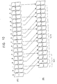
As shown in the figure, the main sector is formed of
141 sync blocks. Each sync block is 888 bits (111 bytes)
long.
In each of the first 123 sync blocks, a 16-bit sync, a
24-bit ID, an 8-bit SB header, 760-bit main data, and a 80-bit
parity C1 are disposed.
The sync is generated by the sync generating section 7.
The ID is added by the error-code and ID adding section 5.
The SB header includes identification information for
identifying the type of the main data, such as audio data,
video data, search video data, transport-stream data, and
AUX data. The controller 13 sends SB-header data through
the terminal 3 as system data.
The main data is video data sent from the video-data
compression section 1, audio data sent from the audio-data
compression section 2, or AUX data sent from the controller
13 through the terminal 3.
The parity C1 is calculated by using the ID, the SB
header, and the main data in each sync block and added by
the error-code and ID adding section 5.
Each of the last 18 sync blocks among the 141 sync
blocks includes a sync, an ID, a parity C2, and a parity C1.
The parity C2 is obtained by calculating the SB headers or
the main data in the vertical direction in Fig. 8. This
calculation is performed by the error-code and ID adding
section 5.
The total amount of data in the main sector is 888 bits
x 141 sync blocks = 125,208 bits. The total amount of data
is 130,425 bits after the 24-to-25 conversion. The
substantial maximum data rate is 760 bits x 123 sync blocks
x 10 tracks x 30 Hz = 28.044 MHz at 60 Hz. This bit rate is
sufficient for recording HD video data, compressed audio
data, AUX data and search video data by the MP@HL or MP@H-14
method.
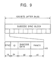
After the main sector, a sub-code sector 1250 bits long
is disposed. Fig. 9 shows the structure of the sub-code
sector.
The sub-code sector in one track is formed of 10 sub-code
sync blocks. One sub-code sync block is formed of a
sync, an ID, sub-code data, and a parity.
At the beginning of the sub-code sector 1250 bits long
(after the 24-to-25 conversion) shown in Fig. 9, a 16-bit
sync is disposed. A 24-bit ID is disposed thereafter. The
sync is added by the sync generating section 7. The ID is
added by the error-code and ID adding section 5.
After the ID code, 40-bit sub-code data is disposed.
This sub-code data is sent from the controller 13 through
the terminal 3, and includes, for example, a track number
and a time code. After the sub-code data, a 40-bit parity
is added. The parity is added by the error-code and ID
adding section 5.
A sub-code sync block has the length (120 bits) before
the 24-to-25 conversion.
After the sub-code sector, a post amble is disposed.
The post amble is also recorded by combining the pattern A
and the pattern B shown in Fig. 7. Its length is 1500 bits
when a synchronization is achieved at 60 x 1000/1001 Hz, and
is 1375 bits when a synchronization is achieved at 60 Hz.
The operation of the apparatus shown in Fig. 1 will be
described next. An HD video signal is input to the video-data
compression section 1, and compressed, for example, by
the MP@HL or MP@H-14 method.
For example, frames for which picture types are
specified as shown in Fig. 10(A), constituting an HD video
are re-arranged in order to ease encoding processing in a
bi-directional prediction, and are encoded as shown in Fig.
10(B) correspondingly to the specified picture types. The
input HD video signal is compressed by the video-data
compression section 1 in this way to generate video data
(hereinafter called video data having a GOP structure of N =
15 and M = 3, if necessary) in which I (intra) pictures are
disposed every 15 pictures (N = 15) and P (predictive)
pictures are disposed every three pictures (M = 3).
The amount of data in each frame shown in Fig. 10(A) is
the same. For example, as shown in Fig. 11A, when the
horizontal direction indicates time and the vertical
direction indicates a bit rate in the figure, each frame is
expressed by a block having the same height and width
(having the same area).
Since a frame having a picture type of I picture is
encoded within the frame, a frame having a picture type of P
picture is prediction-encoded in a forward direction (unidirection),
and a frame having a picture type of B (bi-directional
predictive) picture is prediction-encoded bidirectionally,
the amount of codes in each picture shown in
Fig. 10(B) is different. I pictures have the largest amount
of codes, P pictures next, and then, B pictures. When the
horizontal direction indicates time and the vertical
direction indicates a bit rate as shown in Fig. 11B, since
each picture is compressed by the MPEG method so as to have
the same bit rate, each picture is expressed by a block
having the same height and a different width corresponding
to its amount of codes.
Although it appears in Fig. 11B that all P pictures
have the same size (same amount of codes) and all B pictures
have the same size, they actually have different amounts of
codes according to the videos of their frames, such as image
patterns in the videos. The larger the correlation with the
video of a frame with which a prediction relationship is
obtained is, the smaller the amount of codes is. Even if
the same encoding processing is applied, the amounts of
codes are different.
An HD audio signal is input to the audio-data
compression section 2, and compressed by the same method as
for the DV format. The HD audio signals corresponding to HD
video signals have the same amount of data, and also have
the same amount of codes after the compression.
The controller 13 sends system data formed of sub-code
data, AUX data, and an SB header to the terminal 3.
The switch 4 is controlled by the controller 13 to
appropriately select the output video data (including search
video data) of the video-data compression section 1, the
output auto data of the audio-data compression section 2, or
the system data input from the terminal 3, at a
predetermined timing and to send it to the error-code and ID
adding section 5 to synthesize data.
In this case, data sent to the error-code and ID adding
section 5 is synthesized such that pictures the number of
which is indicated by the value of M in a GOP structure are
handled as a unit, and one-unit pictures (video data) and
the audio data corresponding to the pictures are
collectively arranged.
In the case shown in Fig. 11B, since the value of M in
a GOP structure is three, three pictures are handled as a
unit. An I picture In+2, a B picture Bn, and a B picture Bn+1,
a P picture Pn+5, a B picture Bn+3, and a B picture Bn+4, a P
picture Pn+8, a B picture Bn+6, and a B picture Bn+7, a P
picture Pn+11, a B picture Bn+9, and a B picture Bn+10, and a P
picture Pn+14, a B picture Bn+12, and a B picture Bn+13 are each
handled as one-unit pictures.
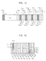
As shown Fig. 12, one-unit video data (pictures) is
continuously arranged, and the corresponding audio data is
also continuously arranged before the video data. For
example, audio data An+2, audio data An, and audio data An+1
corresponding to the I picture In+2, the B picture Bn, and the
B picture Bn+1 are continuously arranged, and following them,
the I picture In+2, the B picture Bn, and the B picture Bn+1
are continuously arranged.
In Fig. 12, An+2, An, and An+1 indicate the audio data
corresponding to the I picture In+2, the B picture Bn, and the
B picture Bn+1, An+5, An+3, and An+4 indicate the audio data
corresponding to the P picture Pn+5, the B picture Bn+3, and
the B picture Bn+4, An+8, An+6, and An+7 indicate the audio data
corresponding to the P picture Pn+8, the B picture Bn+6, and
the B picture Bn+7, An+11, An+9, and An+10 indicate the audio data
corresponding to the P picture Pn+11, the B picture Bn+9, and
the B picture Bn+10, and An+14, An+13, and An+12 indicate the audio
data corresponding to the P picture Pn+14, the B picture Bn+12,
and the B picture Bn+13.
The error-code and ID adding section 5 holds data
synthesized as described above for 16 tracks and interleaves
the data within the 16 tracks.
The error-code and ID adding section 5 adds a 24-bit ID
to each sync block shown in Fig. 8 in the main sector. The
error-code and ID adding section 5 also calculates and adds
a parity C1 shown in Fig. 8 for and to each sync block, and
adds a parity C2 to each of the last 18 sync blocks among
the 141 sync blocks, instead of the SB header and main data.
In addition, as shown in Fig. 9, the error-code and ID
adding section 5 adds a 24-bit ID to each sub-code sync
block in the sub-code sector, and calculates and adds a 40-bit
parity.
The 24-to-25 conversion section 6 converts data sent
from the error-code and ID adding section 5 in units of 24
bits to 25-bit data. With this conversion, the pilot
signals for tracking having frequencies of f1 and f2, shown
in Fig. 3 to Fig. 5, have large magnitudes.
The sync generating section 7 adds a 16-bit
synchronizing data (sync) to each sync block in the main
sector, as shown in Fig. 8. The sync generating section 7
also adds 16-bit synchronizing data (sync) to each sub-code
sync block in the sub-code sector, as shown in Fig. 9. In
addition, the sync generating section 7 generates a run
pattern for a pre-amble or a post-amble shown in Fig. 7.
More specifically, the foregoing data is added
(synthesized) when the controller 13 switches the switch 8
to selectively send the data output from the sync generating
section 7 and the data output from the 24-to-25 conversion
section 6 to the modulation section 9.
The modulation section 9 randomizes input data,
modulates it by a method corresponding to the DV format, and
outputs to the parallel-to-serial conversion section 10.
The parallel-to-serial conversion section 10 converts input
data from parallel data to serial data, and sends it to the
rotating head 12 through the amplifier 11. The rotating
head 12 records input data into the magnetic tape 14.
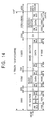
Fig. 13 shows a condition in which data which includes
the audio data An+2 to the B picture Bn+1 among the data
synthesized as shown in Fig. 12 is recorded into the
magnetic tape 14. Specifically, for example, the audio data
An+1 and the I picture In+2 are both recorded in a track T2.
In Fig. 13, tracks formed at an angle against the
longitudinal direction of the magnetic tape 14 are
vertically shown.
As described above, since data is synthesized such that
predetermined-unit video data and the corresponding audio
data are respectively collectively arranged, the data is
recorded in the format having the sector arrangement shown
in Fig. 6, and a video rate of about 28 Mbps is obtained.
In other words, HD video data is compressed and recorded by
the MP@HL or MP@H-14 method.
Conventionally, as shown in Fig. 14, since data is
recorded in the DV format, in which a gap G1 (625 bits), a
gap G2 (700 bits), and a gap G3 (1550 bits) are arranged in
addition to an audio sector having an audio signal and a
video sector having video data, only a video rate of about
24 Mbps is at most obtained except that for search video
data.
Since an HD video signal and an HD audio signal are
collectively recorded in predetermined units as shown in Fig.
13, recorded HD video data can be efficiently tied, for
example, to other HD video data recorded by the MP@HL or
MP@H-14 method. The principle therefor will be described
next by referring to Fig. 15.
Fig. 15(A) imitatively shows an HD video signal and an
HD audio signal (recorded data) recorded by the MP@HL or
MP@H-14 method as shown in Fig. 13 (Fig. 15(A) is
substantially the same as Fig. 12).
Fig. 15(B) imitatively shows an HD video signal and an
HD audio signal formed by the MP@HL or MP@H-14 method,
separately sent, in other words, normal MPEG data to which
the processing of the present invention has not been applied.
In MPEG data, audio data and the corresponding video data
(picture) are alternately arranged.
It is assumed here that the recorded data (Fig. 15(A))
serves as under-recorded data, the normal MPEG data serves
as data to be tied, and the B picture Bn+1 of the recorded
data and an I picture Im of the MPEG data are to be tied. In
this case, audio data Am of the MPEG data is disposed
immediately after the audio data An+5 of the recorded data,
immediately after the audio data An+3, or immediately after
the audio data An+4. With this operation, without including
wasteful video data, the audio signal corresponding to a
copy picture is obtained for tying data.
The first video data of the data tied to under-recorded
data is usually an I picture (in this case, the I picture Im).
Since an I picture has a larger amount of codes than a P
picture and a B picture, as described above, a decoding
buffer generates an underflow or an overflow when the I
picture is decoded according to the amount of codes of the
video data (in this case, the B picture Bn+1) of the under-recorded
data, decoded immediately before the I picture of
the tied data. To prevent the decoding buffer from
generating an underflow or an overflow, a still picture
having an extremely small amount of codes, a so-called copy
picture is inserted at the tying point as video data of the
under-recorded data, decoded immediately before the I
picture of the tied data.
When a copy picture is inserted in this way, however,
since a display time is extended by the amount thereof, data
to be tied is tied after the audio signal of the under-recorded
data which continues before the tying point to
ensure the audio data corresponding to the copy picture.
Specifically, in this case, data to be tied is tied such
that the audio data An+5, the audio data An+3, or the audio
data An+4 of the recorded data serving as under-recorded data
serves as the audio data corresponding to the copy picture.
Conventionally, since an HD video signal and an HD
audio signal formed by the MP@HL or MP@H-14 method are
recorded in the same data arrangement as that of MPEG data
as shown in Fig. 16(A), in other words, since an audio
signal and the corresponding video signal are alternately
arranged and recorded, when they are tied to other MPEG data,
a wasteful video signal is included.
When a B picture Bn+1 in recorded data (data recorded by
a conventional recording method) shown in Fig. 16(A) is tied
to an I picture Im of MPEG data shown in Fig. 16(B), for
example, the I picture Im shown in Fig. 16(B) is tied
immediately after audio data An+5, immediately after audio
data An+3, or immediately after audio data An+4 shown in Fig.
16(A).
In this case, when the I picture Im is tied immediately
after the audio data An+3 shown in Fig. 16(A), a P picture Pn+5
is included. When the I picture Im is tied immediately after
the audio data An+4, a P picture Pn+5 and a B picture Bn+3 are
both included. Consequently, wasteful video data is
included.
In the foregoing description, an HD video signal and an
HD audio signal which have not been compressed by an MPEG
method are used as input signals. An HD video signal and an
HD audio signal which have been compressed by an MPEG method
can be used as input signals.
Fig. 17 shows an example structure of a recording
system in a magnetic-tape recording and reproduction
apparatus to which the present invention is applied, used
when an HD video signal and an HD audio signal compressed by
an MPEG method are input.
The recording system includes a demultiplexer 31, a
video buffer 32, an audio buffer 33, and a delay section 34
in stead of the video-data compression section 1 and the
audio-data compression section 2 used in the case shown in
Fig. 1.
The demultiplexer 31 applies demultiplexing processing
to input MPEG data, sends resultant video data to the video
buffer 32, and sends audio data to the audio buffer 33.
When the MPEG data shown in Fig. 16(A) is input, for
example, the I picture In+2, the B picture Bn, ... are sent to
the video buffer 32, and the audio data An+2, the audio data
An, ... are sent to the audio buffer 33.
The video buffer 32 holds predetermined-unit video data
sent from the demultiplexer 31, and sends it to the delay
section 34. In the case shown in Fig. 16(A), the video
buffer 32 holds video data in units of three pictures (for
example, the I picture In+2, the B picture Bn, and the B
picture Bn+1), the number of which is indicated by the value
of M in the GOP structure, and sends them to the delay
section 34.
The audio buffer 33 holds a predetermined-unit HD audio
signal sent from the demultiplexer 31, and sends it to a
switch 4. In the case shown in Fig. 16(A), the audio buffer
33 holds one-unit audio data (for example, the audio data
An+2, An, An+1) corresponding to three pictures.
The delay section 34 stores (delays) video data sent
from the video buffer 32 for a predetermined time.
The switch 4 is switched by the controller 13 to select
the video data output from the delay section 34, the audio
data output from the audio buffer 33, or system data input
from a terminal 3, at a predetermined timing and to send it
to an error-code and ID adding section 5 to synthesize data.
As a result, as shown in Fig. 12, data is formed such
that audio data and video data are arranged in units of
pictures (three pictures in the case shown in Fig. 12) whose
number is indicated by the value of M in a GOP structure.
Since the error-code and ID adding section 5 to an
amplifier 11 perform the same processes as those described
in the case shown in Fig. 1, a description thereof is
omitted.
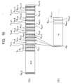
Fig. 18 shows an example structure of a reproduction
system for reproducing data recorded into the magnetic tape
14 as described above.
The rotating head 12 reads data recorded into the
magnetic tape 14, and outputs it to an amplifier 41. The
amplifier 41 amplifies an input signal, and sends it to an
A/D conversion section 42. The A/D conversion section 42
converts an input signal from an analog signal to a digital
signal, and sends it to a demodulation section 43. The
demodulation section 43 randomizes data sent from the A/D
conversion section 42 correspondingly to the randomization
performed by the modulation section 9, and achieves
demodulation by the method corresponding to the modulation
method used by the modulation section 9.
A sync detecting section 44 detects from data
demodulated by the demodulation section 43 a sync
(synchronizing data) in each sync block of the main sector
shown in Fig. 8 and a sync in each sub-code sync block in
the sub-code sector shown in Fig. 9, and sends them to an
error-correcting and ID-detecting section 46. A 25-to-24
conversion section 45 converts data sent from the
demodulation section 43 from 25-bit data to 24-bit data
correspondingly to the conversion performed by the 24-to-25
conversion section 6, and outputs the data to the error-correcting
and ID-detecting section 46.
The error-correcting and ID-detecting section 46
executes error-correcting processing, ID detecting
processing, and deinterleaving processing by using syncs
input from the sync detecting section 44.
A switch 47 is controlled by the controller 13 to
output video data (including search video data) to output a
video-data decompression section 48, audio data to an audio-data
decompression section 49, and system data, such as sub-code
data and AUX data, to the controller 13 through a
terminal 50 among data output from the error-correcting and
ID-detecting section 46.
The video-data decompression section 48 decompresses
input video data, apply D/A conversion, and outputs as an
analog HD video signal. The audio-data decompression
section 49 decompresses input audio data, apply D/A
conversion, and outputs as an analog audio data.
The operation of the reproduction system will be
described next. The rotating head 12 reads data recorded
into the magnetic tape 14 in the form shown in Fig. 13, and
the amplifier 41 amplifies it and sends it to the A/D
conversion section 42. The A/D conversion section 42
converts an input analog signal to a digital signal, and
sends it to the demodulation section 43. The demodulation
section 43 randomizes and demodulates data by the method
corresponding to the randomization and the modulation method
used by the modulation section 9 shown in Fig. 1.
The 25-to-24 conversion section 45 converts data
demodulated by the demodulation section 43 from 25-bit data
to 24-bit data, and outputs the data to the error-correcting
and ID-detecting section 46.
The sync detecting section 44 detects from data output
from the demodulation section 43 sync's in the main sector
shown in Fig. 8 or sync's in the sub-code sector shown in
Fig. 9, and sends them to the error-correcting and ID-detecting
section 46. The error-correcting and ID-detecting
section 46 stores data for 16 tracks, applies deinterleaving,
and achieves error-correcting processing with the use of the
parities C1 and C2 of the main sector shown in Fig. 8. The
error-correcting and ID-detecting section 46 also detects an
SB header in the main sector to determine whether data
included in each sync block is audio data, video data, AUX
data, or search video data.
In addition, the error-correcting and ID-detecting
section 46 uses the parity of the sub-code sector shown in
Fig. 9 to apply error-correcting processing to sub-code data,
and detects an ID to determine the type of the sub-code data.
With this operation, it is determined whether the sub-code
data indicates a track number or a time-code number.
The switch 47 sends video data and search video data to
the video-data decompression section 48 according to the SB
header detected by the error-correcting and ID-detecting
section 46. The video-data decompression section 48
decompresses input data by the method corresponding to the
compression method used by the video-data compression
section 1 shown in Fig. 1, and outputs as a video signal.
The switch 47 outputs audio data to the audio-data
decompression section 49. The audio-data decompression
section 49 decompresses input audio data by the method
corresponding to the compression method used by the audio-data
compression section 2 shown in Fig. 1, and outputs as
an audio signal.
The switch 47 outputs AUX data and sub-code data output
from the error-correcting and ID-detecting section 46 to the
controller 13 through the terminal 50.
As a result, pictures and audio data in data recorded
as shown in Fig. 13, for example, are decompressed
correspondingly to a normal data arrangement of MPEG data
shown in Fig. 16(A).
In the foregoing description, pictures and audio data
recorded into the magnetic tape 14 are decompressed. They
may be multiplexed to form MPEG data.
Fig. 19 shows a recording system according to another
embodiment. In this embodiment, an HD video signal, the
corresponding audio signal (HD audio signal), and system
data (HD system data) can be recorded into a magnetic tape
14 by an MPEG method in the same way as in the case shown in
Fig. 1. In addition, a standard-quality video signal
(standard-density (SD) video signal), an SD audio signal,
and SD system data can also be recorded by the same
commercial DV format as that conventionally used.
More specifically, in the embodiment shown in Fig. 19,
a commercial-DV-method recording-signal processing section
62 for processing an SD video signal, an SD audio signal,
and SD system data is provided in addition to an MPEG-method
recording-signal processing section 61 which includes the
video-data compression section 1, the audio-data compression
section 2, the terminal 3, the switch 4, and the error-correcting
and ID adding section 5. A switch 63 is
controlled by a controller 13 to select the output of the
MPEG-method recording-signal processing section 61 or the
output of the commercial-DV-method recording-signal
processing section 62, and sends to a 24-to-25 conversion
section 6.
In the embodiment shown in Fig. 19, an ITI generating
section 64 is further provided. The ITI generating section
64 generates data for an insert-and-track-information (ITI)
sector to be disposed in the conventional track shown in Fig.
14, and sends it to a switch 8. The switch 8 selects the
output of the 24-to-25 conversion section 6, the output of a
sync generating section 7, or the output of the ITI
generating section 64, and outputs to a modulation section 9.
The other portions are the same as those used in the case
shown in Fig. 1.
In the present embodiment, an HD video signal, the
corresponding HD audio signal, and HD system data are
recorded (since the operation is the same as that in the
case shown in Fig. 1, a description thereof is omitted) into
a magnetic tape 14 in the same way as in the embodiment
shown in Fig. 1. In addition, the commercial-DV-method
recording-signal processing section 62 applies signal
processing to an input SD video signal, the corresponding SD
audio signal, and SD system data, in the DV format.
Data output from the commercial-DV-method recording-signal
processing section 62 is sent to the 24-to-25
conversion section 6 through the switch 63, and is converted
from 24-bit data to 25-bit data. The switch 8 selects the
data output from the 24-to-25 conversion section 6, a sync
or an amble output from the sync generating section 7, or
data (data in the ITI sector shown in Fig. 14) output from
the ITI generating section 64, at a predetermined timing,
and outputs to a modulation section 9. The modulation
section 9 modulates input data and outputs to a parallel-to-serial
conversion section 10. The parallel-to-serial
conversion section 10 converts parallel data to serial data.
The data output from the parallel-to-serial conversion
section 10 is amplified by an amplifier 11, and recorded
into the magnetic tape 14 by a rotating head 12.
As described above, data is recorded into the magnetic
tape 14 with tracks having the DV format shown in Fig. 14.
The error-code and ID adding section 5 shown in Fig. 1,
built in the MPEG-method recording-signal processing section
61 records identification information indicating that data
currently being recorded is data compressed by the MPEG
method, into the ID of the main sector shown in Fig. 8 and
the ID of the sub-code sector shown in Fig. 9.
As the commercial-DV-method recording-signal processing
section 62, the 24-to-25 conversion section 6, the ITI
generating section 64, the switch 8, the modulation section
9, the parallel-to-serial conversion section 10, the
amplifier 11, and the rotating head 12 shown in Fig. 19, the
same circuit devices as those used in the conventional
commercial DV method can be used. Among them, the 24-to-25
conversion section 6, the switch 8, the modulation section 9,
the parallel-to-serial conversion section 10, the amplifier
11, and the rotating head 12 are used both for recording an
SD video signal and for recording an HD video signal.
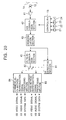
Fig. 20 shows an example structure of a reproduction
system corresponding to the recording system shown in Fig.
19. In this example structure, an ID detecting section 81
determines from the ID in the main sector shown in Fig. 8 or
the ID in the sub-code sector shown in Fig. 9, included in
the output of a demodulation section 43, that data being
reproduced is the data of an HD video signal compressed by
the MPEG method. The ID detecting section 81 also detects
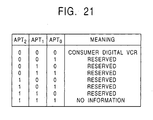
APT2, APT1, and APT0 recorded in a track information area
(TIA) of an ITI sector shown in Fig. 21. As shown in Fig.
21, APT2, APT1, and APT0 are set to all zero for a consumer
digital video cassette recorder. Therefore, from the values,
it can be identified whether data being reproduced is the
data of an SD video signal having the commercial DV method.
When it is determined that data being reproduced is the
data of an HD video signal, the ID detecting section 81
switches a switch 82 to an MPEG-method reproduction-signal
processing section 83 to send data output from a 25-to-24
conversion section 45 to the MPEG-method reproduction-signal
processing section 83. When it is determined that data
being reproduced is the data of an SD video signal in the
commercial DV method, the switch 82 is switched to the upper
side in Fig. 20 to send data output from the 25-to-24
conversion section 45 to a commercial-DV-method
reproduction-signal processing section 84.
The MPEG-method reproduction-signal processing section
83 includes the sync detecting section 44, the error-correcting
and ID-detecting section 46, the switch 47, the
video-data decompression section 48, the audio-data
decompression section 49, and the terminal 50 shown in Fig.
18.
The other circuit devices are the same as in the case
shown in Fig. 18.
More specifically, in the embodiment shown in Fig. 20,
the ID detecting section 81 determines from data output from
a demodulation section 43 whether reproduction data is MPEG-method
data (data of an HD video signal) or commercial-DV-method
data (data of an SD video signal). When it is
determined that reproduction data is MPEG-method data, data
output from the 25-to-24 conversion section 35 is sent to
the MPEG-method reproduction-signal processing section 83
through the switch 82 and processed. In this case, the same
processing as that performed in the case shown in Fig 18 is
applied.
When the ID detecting section 81 determines that data
output from the demodulation section 43 is data having the
commercial-DV-method format, the ID detecting section 81
switches the switch 82 to send the output of the 25-to-24
conversion section to the commercial-DV-method reproduction-signal
processing section 84. The commercial-DV-method
reproduction-signal processing section 84 decompresses input
data by the DV-format method, and outputs as an SD video
signal, an SD audio signal, and SD system data.
In the structure shown in Fig. 20, a rotating head 12,
an amplifier 41, an A/D conversion section 42, the
demodulation section 43, and the 25-to-24 conversion section
45 are used both for reproducing an SD video signal and for
reproducing an HD video signal.
The above-described series of processing can be
executed by software as well as by hardware. When the
series of processing is achieved by software, a program
constituting the software is installed from a recording
medium to a computer built in a special hardware, or to a
unit which can execute various functions after various
programs are installed therein, such as a general-purpose
personal computer.
The recording medium can be a package medium which
stores the program and is distributed for providing the
users with the program, separately from a magnetic-tape
recording and reproduction apparatus, as shown in Fig. 1,
Fig. 17, and Fig. 20, such as a magnetic disk 21 (including
a floppy disk), an optical disk 22 (including a compact
disk-read only memory (CD-ROM) and a digital versatile disk
(DVD)), a magneto-optical disk 23 (including a Mini-disk
(MD)), or a semiconductor memory 24. The recording medium
can also be a device which stores the program and is
provided for the users in a state in which it is built in an
apparatus in advance, such as a ROM or a hard disk.
In the present specification, steps describing the
program stored in a recording medium include processes
performed in a time sequential manner in the order in which
they are described, and in addition, include processes which
are not necessarily performed in a time sequential manner
but executed in parallel or independently.
According to a magnetic-tape recording apparatus, a
magnetic-tape recording method, and a program stored in a
recording medium of the present invention, predetermined-unit
video data is taken, audio data corresponding to the
predetermined-unit video data is taken, and the
predetermined-unit video data and the audio data
corresponding to the predetermined-unit video data are
synthesized such that they are continuous on a track in a
magnetic tape without any space disposed therebetween and
sent for recording on the magnetic tape. Therefore, a large
amount of data, typical of which is the data of an HD video
signal, can be recorded on the magnetic tape in a digital
manner, and tying processing can be efficiently applied to
video signals.
According to a magnetic-tape reproduction apparatus, a
magnetic-tape reproduction method, and a program stored in a
recording medium of the present invention, compressed high-quality
video data included in data reproduced by a rotating
head from a magnetic tape is decompressed, compressed audio
data included in the data reproduced by the rotating head
from the magnetic tape is decompressed, distinguish
information for distinguishing the video data from the audio
data is detected from the data reproduced by the rotating
head from the magnetic tape, and the data reproduced from
the magnetic tape is processed according to the result of
detection. Therefore, high-quality video data as well as
standard-quality video data can be positively read.
In so far as the embodiments of the invention
described above are implemented, at least in part, using
software-controlled data processing apparatus, it will be
appreciated that a computer program providing such
software control and a storage medium by which such a
computer program is stored are envisaged as aspects of the
present invention.
Various different aspects and features of the present
invention are defined in the appended claims.
Combinations of features from the dependent claims may be
combined with features of the independent claims as
appropriate and not merely as explicitly set out in the
claims.
Claims (10)
- A magnetic-tape recording apparatus for recording digital data on a magnetic tape by a rotating head, comprising:first obtaining means for obtaining predetermined-unit video data;second obtaining means for obtaining audio data corresponding to the predetermined-unit video data;synthesizing means for synthesizing the predetermined-unit video data and the audio data corresponding to the predetermined-unit video data such that they are continuous on a track in the magnetic tape without any space disposed therebetween; andsending means for sending data synthesized by the synthesizing means to the rotating head in order to record the data on the magnetic tape.
- A magnetic-tape recording apparatus according to Claim 1, further comprising compression means for compressing the high-quality video data obtained by the first obtaining means,wherein the first obtaining means obtains, as the video data, high-quality video data; andthe predetermined-unit video data is the data of pictures whose number is indicated by the value of M in a GOP structure.
- A magnetic-tape recording apparatus according to Claim 2, wherein the compression means compresses the high-quality video data by an MP@HL or MP@H-14 method.
- A magnetic-tape recording apparatus according to Claim 2, further comprising third obtaining means for obtaining, as the video data, compressed standard video data,wherein the high-quality video data obtained by the first obtaining means includes distinguish information for distinguishing the high-quality video data from the standard video data; andthe synthesizing means selects the high-quality video data compressed by the compression means or the compressed standard video data obtained by the third obtaining means and synthesizes.
- A magnetic-tape recording method for a magnetic-tape recording apparatus for recording digital data on a magnetic tape by a rotating head, comprising:a first obtaining step of obtaining predetermined-unit video data;a second obtaining step of obtaining audio data corresponding to the predetermined-unit video data;a synthesizing step of synthesizing the predetermined-unit video data and the audio data corresponding to the predetermined-unit video data such that they are continuous on a track in the magnetic tape without any space disposed therebetween; anda sending step of sending data synthesized by a process in the synthesizing step to the rotating head in order to record the data on the magnetic tape.
- A recording medium for recording a computer-readable program which controls a magnetic-tape recording apparatus for recording digital data on a magnetic tape by a rotating head, the program comprising:a first obtaining step of obtaining predetermined-unit video data;a second obtaining step of obtaining audio data corresponding to the predetermined-unit video data;a synthesizing step of synthesizing the predetermined-unit video data and the audio data corresponding to the predetermined-unit video data such that they are continuous on a track in the magnetic tape without any space disposed therebetween; anda sending step of sending data synthesized by a process in the synthesizing step to the rotating head in order to record the data on the magnetic tape.
- A magnetic-tape reproduction apparatus for reading by a rotating head a magnetic tape into which compressed, high-quality or standard, predetermined-unit, video data and audio data corresponding to the predetermined-unit video data are recorded such that they are continuous on a track without any space disposed therebetween, comprising:first decompression means for decompressing the compressed, high-quality video data among data read from the magnetic tape by the rotating head;second decompression means for decompressing the compressed audio data among the data read from the magnetic tape by the rotating head;detecting means for detecting distinguish information for distinguishing the video data from the audio data, from the data read from the magnetic tape by the rotating head; andselection means for selecting the first decompression means or the second decompression means according to the result of detection performed by the detecting means to process the data read from the magnetic tape by the rotating head.
- A magnetic-tape reproduction apparatus according to Claim 7, wherein the first decompression means decompresses the high-quality video data by an MP@HL or MP@H-14 method.
- A magnetic-tape reproduction method for a magnetic-tape reproduction apparatus for reading by a rotating head a magnetic tape into which compressed, high-quality or standard, predetermined-unit, video data and audio data corresponding to the predetermined-unit video data are recorded such that they are continuous on a track without any space disposed therebetween, comprising:a first decompression step of decompressing the compressed, high-quality video data among data read from the magnetic tape by the rotating head;a second decompression step of decompressing the compressed audio data among the data read from the magnetic tape by the rotating head;a detecting step of detecting distinguish information for distinguishing the video data from the audio data, from the data read from the magnetic tape by the rotating head; anda selection step of selecting a process performed in the first decompression step or in the second decompression step according to the result of detection performed in the detecting step to process the data read from the magnetic tape by the rotating head.
- A recording medium for recording a computer-readable program which controls a magnetic-tape reproduction apparatus for reading by a rotating head a magnetic tape into which compressed, high-quality or standard, predetermined-unit, video data and audio data corresponding to the predetermined-unit video data are recorded such that they are continuous on a track without any space disposed therebetween, the program comprising:a first decompression step of decompressing the compressed, high-quality video data among data read from the magnetic tape by the rotating head;a second decompression step of decompressing the compressed audio data among the data read from the magnetic tape by the rotating head;a detecting step of detecting distinguish information for distinguishing the video data from the audio data among the data read from the magnetic tape by the rotating head; anda selection step of selecting a process performed in the first decompression step or in the second decompression step according to the result of detection performed in the detecting step to process the data read from the magnetic tape by the rotating head.
Applications Claiming Priority (2)
| Application Number | Priority Date | Filing Date | Title |
|---|---|---|---|
| JP2000093896 | 2000-03-30 | ||
| JP2000093896A JP4345190B2 (en) | 2000-03-30 | 2000-03-30 | Magnetic tape recording apparatus and method |
Publications (1)
| Publication Number | Publication Date |
|---|---|
| EP1148740A2 true EP1148740A2 (en) | 2001-10-24 |
Family
ID=18609019
Family Applications (1)
| Application Number | Title | Priority Date | Filing Date |
|---|---|---|---|
| EP01303002A Withdrawn EP1148740A2 (en) | 2000-03-30 | 2001-03-29 | Magnetic tape recording apparatus and method, magnetic tape reproduction apparatus and method, and recording medium |
Country Status (6)
| Country | Link |
|---|---|
| US (1) | US7200324B2 (en) |
| EP (1) | EP1148740A2 (en) |
| JP (1) | JP4345190B2 (en) |
| KR (1) | KR100772285B1 (en) |
| CN (1) | CN1168325C (en) |
| AU (1) | AU783408B2 (en) |
Cited By (1)
| Publication number | Priority date | Publication date | Assignee | Title |
|---|---|---|---|---|
| EP1148472A3 (en) * | 2000-04-06 | 2008-03-05 | Sony Corporation | Magnetic tape recording apparatus and method, magnetic tape playback apparatus and method, format for magnetic tape, and storage medium product |
Families Citing this family (4)
| Publication number | Priority date | Publication date | Assignee | Title |
|---|---|---|---|---|
| EP2923497A4 (en) * | 2012-11-21 | 2016-05-18 | H4 Eng Inc | Automatic cameraman, automatic recording system and video recording network |
| CN113795882B (en) * | 2019-09-27 | 2022-11-25 | 华为技术有限公司 | Emotion-based multimedia content summarization |
| CN110839135B (en) * | 2019-12-04 | 2022-05-27 | 厦门市美亚柏科信息股份有限公司 | Recovery method and system for DV or HDV video file |
| CN111083396B (en) * | 2019-12-26 | 2022-08-02 | 北京奇艺世纪科技有限公司 | Video synthesis method and device, electronic equipment and computer-readable storage medium |
Family Cites Families (10)
| Publication number | Priority date | Publication date | Assignee | Title |
|---|---|---|---|---|
| GB2220521B (en) * | 1988-06-07 | 1993-04-28 | Mitsubishi Electric Corp | Digital signal recording method a digital video tape recorder and a recorded tape |
| US5574570A (en) * | 1992-05-12 | 1996-11-12 | Mitsubishi Denki Kabushiki Kaisha | Video signal recording/reproduction apparatus and method for recording/reproducing two kinds of video signals carrying different amounts of information |
| US5623344A (en) * | 1992-09-01 | 1997-04-22 | Hitachi America, Ltd. | Digital video recording device with trick play capability |
| JP2932886B2 (en) * | 1993-03-10 | 1999-08-09 | 松下電器産業株式会社 | Digital signal recording method |
| KR0165656B1 (en) * | 1993-07-08 | 1999-03-20 | 모리시타 요이찌 | Apparatus for transmitting data |
| US6115537A (en) * | 1994-02-18 | 2000-09-05 | Matsushita Electric Industrial Co., Ltd. | Digital signal recording and reproducing apparatus |
| MY114287A (en) * | 1994-12-26 | 2002-09-30 | Sony Corp | Digital video recorder |
| KR0182026B1 (en) * | 1995-12-21 | 1999-05-01 | 김광호 | Syntax analyser for mpeg video decoder |
| JP2000287153A (en) * | 1999-03-31 | 2000-10-13 | Sony Corp | Magnetic recording / reproducing method and apparatus |
| JP2001275077A (en) * | 2000-03-27 | 2001-10-05 | Sony Corp | Magnetic tape recording device and method, magnetic tape reproducing device and method, magnetic tape format, and recording medium |
-
2000
- 2000-03-30 JP JP2000093896A patent/JP4345190B2/en not_active Expired - Fee Related
-
2001
- 2001-03-27 AU AU31346/01A patent/AU783408B2/en not_active Ceased
- 2001-03-29 EP EP01303002A patent/EP1148740A2/en not_active Withdrawn
- 2001-03-29 US US09/821,321 patent/US7200324B2/en not_active Expired - Fee Related
- 2001-03-30 CN CNB011192992A patent/CN1168325C/en not_active Expired - Fee Related
- 2001-03-30 KR KR1020010016916A patent/KR100772285B1/en not_active Expired - Fee Related
Cited By (1)
| Publication number | Priority date | Publication date | Assignee | Title |
|---|---|---|---|---|
| EP1148472A3 (en) * | 2000-04-06 | 2008-03-05 | Sony Corporation | Magnetic tape recording apparatus and method, magnetic tape playback apparatus and method, format for magnetic tape, and storage medium product |
Also Published As
| Publication number | Publication date |
|---|---|
| AU783408B2 (en) | 2005-10-27 |
| US7200324B2 (en) | 2007-04-03 |
| JP4345190B2 (en) | 2009-10-14 |
| CN1333628A (en) | 2002-01-30 |
| JP2001285769A (en) | 2001-10-12 |
| KR100772285B1 (en) | 2007-11-01 |
| AU3134601A (en) | 2001-10-04 |
| US20010043785A1 (en) | 2001-11-22 |
| CN1168325C (en) | 2004-09-22 |
| KR20010095171A (en) | 2001-11-03 |
Similar Documents
| Publication | Publication Date | Title |
|---|---|---|
| JPH1131363A (en) | Digital recording / reproducing apparatus and method having improved error correction capability | |
| US5995707A (en) | Speed change reproduction recording apparatus for VCR of digital HDTV and method thereof | |
| US6950603B1 (en) | Digital signal, processing apparatus, digital signal processing method, digital signal recording apparatus, digital signal reproducing apparatus, and digital video-audio signal recording and reproducing apparatus | |
| KR100746538B1 (en) | Magnetic tape recording apparatus and method, magnetic tape reproducing apparatus and method, format of magnetic tape, and recording medium | |
| US7200324B2 (en) | Magnetic-tape recording apparatus and method, magnetic-tape reproduction apparatus and method, and recording medium | |
| KR100187349B1 (en) | Compressed television signal recording and reproducing apparatus | |
| KR100719780B1 (en) | Data transfer apparatus and method, recording apparatus and recording and reproducing apparatus | |
| US7062154B2 (en) | Magnetic-tape recording apparatus, magnetic-tape recording method, magnetic-tape format, and recording medium | |
| KR100746527B1 (en) | Magnetic tape recording apparatus and method, magnetic tape reproducing apparatus and method, magnetic tape, and recording media | |
| KR20010050137A (en) | Digital signal recording apparatus and recording medium | |
| KR100630243B1 (en) | Magnetic recording apparatus and method for digital signals, Magnetic reproduction apparatus and method for digital signals, Tape-type recording media | |
| JP3334354B2 (en) | Variable speed playback method and playback apparatus for digital video signal | |
| JP2004015457A (en) | Video tape recorder | |
| US7421190B2 (en) | Video tape recorder and recording method | |
| US7447420B2 (en) | Recording apparatus for recording encoded data together with sync data | |
| JPH06302103A (en) | Digital information recording device and digital information reproducing device | |
| JP3384162B2 (en) | Digital video signal recording / reproducing device | |
| JP4164769B2 (en) | Video tape recorder and recording method | |
| KR20050122173A (en) | Recording apparatus and method | |
| JP2004112826A (en) | Information recording apparatus, information recording method, information reproducing apparatus, and information reproducing method | |
| JPH08130708A (en) | Video signal reproducing device, recording device, recording / reproducing device | |
| JP2004187172A (en) | Information recording apparatus, information recording method, and recording medium | |
| JPH05342697A (en) | Video signal recorder | |
| JPH08279207A (en) | Digital signal recording / reproducing device |
Legal Events
| Date | Code | Title | Description |
|---|---|---|---|
| PUAI | Public reference made under article 153(3) epc to a published international application that has entered the european phase |
Free format text: ORIGINAL CODE: 0009012 |
|
| AK | Designated contracting states |
Kind code of ref document: A2 Designated state(s): AT BE CH CY DE DK ES FI FR GB GR IE IT LI LU MC NL PT SE TR |
|
| AX | Request for extension of the european patent |
Free format text: AL;LT;LV;MK;RO;SI |
|
| STAA | Information on the status of an ep patent application or granted ep patent |
Free format text: STATUS: THE APPLICATION HAS BEEN WITHDRAWN |
|
| 18W | Application withdrawn |
Withdrawal date: 20020617 |