EP1148644A2 - Pseudo-random number sequence output unit, transmitter, receiver, communication system and filter unit, pseudo-random number sequence output method, transmission method, receiving method and filtering method, and data recording medium - Google Patents
Pseudo-random number sequence output unit, transmitter, receiver, communication system and filter unit, pseudo-random number sequence output method, transmission method, receiving method and filtering method, and data recording medium Download PDFInfo
- Publication number
- EP1148644A2 EP1148644A2 EP01303032A EP01303032A EP1148644A2 EP 1148644 A2 EP1148644 A2 EP 1148644A2 EP 01303032 A EP01303032 A EP 01303032A EP 01303032 A EP01303032 A EP 01303032A EP 1148644 A2 EP1148644 A2 EP 1148644A2
- Authority
- EP
- European Patent Office
- Prior art keywords
- pseudo
- random number
- output
- initial values
- signal
- Prior art date
- Legal status (The legal status is an assumption and is not a legal conclusion. Google has not performed a legal analysis and makes no representation as to the accuracy of the status listed.)
- Withdrawn
Links
Images





Classifications
-
- H—ELECTRICITY
- H04—ELECTRIC COMMUNICATION TECHNIQUE
- H04J—MULTIPLEX COMMUNICATION
- H04J13/00—Code division multiplex systems
- H04J13/10—Code generation
-
- G—PHYSICS
- G06—COMPUTING OR CALCULATING; COUNTING
- G06F—ELECTRIC DIGITAL DATA PROCESSING
- G06F7/00—Methods or arrangements for processing data by operating upon the order or content of the data handled
- G06F7/58—Random or pseudo-random number generators
- G06F7/582—Pseudo-random number generators
- G06F7/586—Pseudo-random number generators using an integer algorithm, e.g. using linear congruential method
-
- H—ELECTRICITY
- H04—ELECTRIC COMMUNICATION TECHNIQUE
- H04J—MULTIPLEX COMMUNICATION
- H04J13/00—Code division multiplex systems
- H04J13/0007—Code type
- H04J13/0022—PN, e.g. Kronecker
-
- H—ELECTRICITY
- H04—ELECTRIC COMMUNICATION TECHNIQUE
- H04B—TRANSMISSION
- H04B1/00—Details of transmission systems, not covered by a single one of groups H04B3/00 - H04B13/00; Details of transmission systems not characterised by the medium used for transmission
- H04B1/69—Spread spectrum techniques
- H04B1/707—Spread spectrum techniques using direct sequence modulation
-
- H—ELECTRICITY
- H04—ELECTRIC COMMUNICATION TECHNIQUE
- H04J—MULTIPLEX COMMUNICATION
- H04J13/00—Code division multiplex systems
- H04J13/0007—Code type
- H04J13/0018—Chaotic
Definitions
- This invention relates to a pseudo-random number sequence output unit, transmitter, receiver, communication system and filter unit, a pseudo-random number sequence output method, transmission method and receiving method, and a data recording medium.
- This invention particularly relates to an output unit and output method suitable for outputting pseudo-random number sequences usable as the spreading codes of an asynchronous CDMA (Code Division Multiple Access) system for satellite, point-to-point, mobile phone and PHS (Personal Handyphone System) communication systems and other land mobile communication systems, and in GPS (Global Positioning System) and other distance measurement fields; a transmitter, receiver, communication system, filter unit, transmission method, receiving method and filtering method using the spreading codes; and a computer-readable data recording medium recorded with a program for implementing any of the foregoing.
- CDMA Code Division Multiple Access
- PHS Personal Handyphone System
- Spreading codes developed for enabling spread-spectrum communication systems and code division multiple telecommunication include M sequences, Kasami sequences and Gold sequences generated by an LFSR (Linear Feedback Shift Register). These spreading code sequences have the following two characteristics.
- the auto-correlation function of codes has a peak and the correlation between different codes (cross-correlation) is near 0. This is very similar to the property of white noise.
- TDMA Time Division Multiple Access
- FDMA Frequency Division Multiple Access
- the asynchronous CDMA communication system differs from these in its feature of enabling despreading by use of the correlation characteristic of the used codes even without positive signal synchronization. It is therefore superior in privacy, secrecy, anti-interference property, anti-jamming property and the like.
- IMT-2000 International Mobile Telecommunication 2000
- ITU International Telecommunication Union
- “Asymptotical” here refers to the case where the user number (number of users) K and the code length N have become large.
- the piecewise-linear maps with the parameter that determines how the correlation function attenuates cannot be freely designed with respect to an arbitrary r (-1 ⁇ r ⁇ 1).
- An object of the present invention is to provide a pseudo-random number sequence output unit, transmitter, receiver, communication system and filter unit, and a pseudo-random number sequence output method, transmission method, receiving method and filtering method that are suitable for an asynchronous CDMA communication system, and a data recording medium recorded with a program for implementing any of the foregoing
- the present invention provides a pseudo-random number sequence output unit comprising an input acceptance section, a calculation section and an output section, which output unit is responsive to s (1 ⁇ s) number of prescribed positive integers q 1 , q 2 , ..., q s , a prescribed real impulse constant r (-1 ⁇ r ⁇ 1), and a prescribed nonzero real constant C for outputting a pseudo-random number sequence of length N (1 ⁇ N).
- the input acceptance section accepts input of:
- the calculation section uses the prescribed real impulse constant r , the prescribed non-zero constant C, the sequence initial values Y 1 , Y 2 , ..., Y s , the integer parameters p 1 , p 2 , ..., p s , the prescribed positive integers q 1 , q 2 , ..., q s and integers j (1 ⁇ j ⁇ s), m (1 ⁇ m ⁇ 2N-2) and n (1 ⁇ n ⁇ 2N-1) to calculate from the recurrence formula: a pseudo-random number sequence z'[1], z'[2], ..., z'[N] of length N that satisfies:
- the output section outputs the pseudo-random number sequence z'[1], z'[2], ..., z'[N].
- the pseudo-random number sequence output unit can be constructed so that the prescribed real impulse constant r satisfies: 2- 3 -0.1 ⁇ r ⁇ 2- 3 +0.1.
- the pseudo-random number sequence output unit can be constructed so that every prescribed positive integer q 1 , q 2 ... q s is 1.
- the present invention provides a transmitter comprising an input acceptance section, the aforesaid pseudo-random number sequence output unit, a spreading section, and a signal transmitting section.
- the input acceptance section accepts input of a signal for transmission.
- the output unit outputs a pseudo-random number sequence of length N.
- the spreading section uses the output pseudo-random number sequence of length N as a spreading code to spectrum-spread the signal for transmission whose input was accepted.
- the signal transmitting section transmits the spectrum-spread signal.
- the transmitter of the present invention can further comprise a selecting section and a parameter transmitting section.
- the selecting section selects sequence initial values Y 1 , Y 2 , ..., Y s and integer parameters p 1 , p 2 , ..., p s .
- the parameter transmitting section transmits the selected sequence initial values Y 1 , Y 2 , ..., Y s and integer parameters p 1 , p 2 , ..., p s .
- the output unit accepts input of the selected sequence initial values Y 1 , Y 2 , ..., Y s and integer parameters p 1 , p 2 , ..., p s and outputs a pseudo-random number sequence of length N.
- the transmitter of the present invention can further comprise a parameter receiving section.
- the parameter receiving section receives sequence initial values Y 1 , Y 2 , ..., Y s and integer parameters p 1 , p 2 , ..., p s
- the output unit accepts input of the received sequence initial values Y 1 , Y 2 , ..., Y s and integer parameters p 1 , p 2 , ..., p s and outputs a pseudo-random number sequence of length N.
- the present invention provides a receiver comprising a signal receiving section, the aforesaid pseudo-random number sequence output unit, an inverse spreading section and an output section.
- the signal receiving section receives a signal.
- the output unit outputs a pseudo-random number sequence of length N.
- the inverse spreading section uses the output pseudo-random number sequence of length N as a spreading code to inversely spectrum-spread the received signal.
- the output section outputs the inversely spectrum-spread signal as a signal for transmission.
- the receiver of the present invention can further comprise a selecting section and a parameter transmitting section.
- the selecting section selects sequence initial values Y 1 , Y 2 , ..., Y s and integer parameters p 1 , p 2 , ..., p s .
- the parameter transmitting section transmits the selected sequence initial values Y 1 , Y 2 , ..., Y s and integer parameters p 1 , p 2 , ..., p s .
- the output unit accepts input of the selected sequence initial values Y 1 , Y 2 , ..., Y s and integer parameters p 1 , p 2 , ..., p s and outputs a pseudo-random number sequence of length N.
- the receiver of the present invention can further comprise a parameter receiving section.
- the parameter receiving section receives sequence initial values Y 1 , Y 2 , ..., Y s and integer parameters p 1 , p 2 , ..., p s .
- the output unit accepts input of the received sequence initial values Y 1 , Y 2 , ..., Y s and integer parameters p 1 , p 2 , ..., p s and outputs a pseudo-random number sequence of length N.
- the present invention provides a communication system comprising the aforesaid transmitter and receiver.
- the receiver receives sequence initial values Y 1 , Y 2 , ..., Y s and integer parameters p 1 , p 2 , ..., p s transmitted by the transmitter.
- the receiver also receives a signal transmitted by the transmitter.
- the present invention provides a communication system comprising the aforesaid transmitter and receiver.
- the transmitter receives sequence initial values Y 1 , Y 2 , ..., Y s and integer parameters p 1 , p 2 , ..., p s transmitted by the receiver.
- the receiver receives a signal transmitted by the transmitter.
- the present invention provides a filter unit comprising an input terminal, a delay section, an amplifying section, an adder section and an output terminal, which filter unit filters according to a prescribed real impulse constant r (-1 ⁇ r ⁇ 1).
- the input terminal accepts input of an input signal of chip length D.
- the delay section outputs a plurality of signals produced by delaying the input signal whose input was accepted by 0, D, 2D, 3D, ..., (N-1)D.
- the amplifying section amplifies the delayed output signals (-r) (N-T)/D times, where T is the delay time, and outputs the amplified signals.
- the adder section sums the output amplified signals and outputs the resulting sum signal.
- the output terminal outputs the output sum signal.
- the delay section, amplifying section and adder section of the filter of the present invention can be constituted as an ASIC (Application Specific Integrated Circuit), a DSP (Digital Signal Processor) or an FPGA (Field Programmable Gate Array)
- ASIC Application Specific Integrated Circuit
- DSP Digital Signal Processor
- FPGA Field Programmable Gate Array
- the; present invention provides a pseudo-random number sequence output method comprising an input acceptance step, a calculation step and an output step, which method is responsive to s (1 ⁇ s) number of prescribed positive integers q 1 , q 2 , ..., q s , a prescribed real impulse constant r (-1 ⁇ r ⁇ 1), a prescribed non-zero real constant C for producing a pseudo-random number sequence of length N (1 ⁇ N).
- input is accepted of:
- the prescribed real impulse constant r the prescribed nonzero real constant C, the sequence initial values Y 1 , Y 2 , ..., Y s , the integer parameters p 1 , p 2 , ..., p s , the prescribed positive integers q 1 , q 2 , ..., q s and integers j (1 ⁇ j ⁇ s), m (1 ⁇ m ⁇ 2N-2) and n (1 ⁇ n ⁇ 2N-1) are used to calculate from the recurrence Formula (4) a pseudo-random number sequence z' [1], z'[2], ..., z'[N] of length N that satisfies (5).
- the pseudo-random number sequence z' [1], z' [2], ..., z' [N] is output.
- the pseudo-random nurnber sequence output method according to the present invention can be constructed so that the sequence initial values Y 1 , Y 2 , ..., Y s satisfy (6) with respect to an integer k (1 ⁇ k ⁇ s) and an integer m (1 ⁇ m ⁇ N).
- the pseudo-random number sequence output method according to the present invention can be constructed so that the prescribed real impulse constant r satisfies (7).
- the pseudo-random number sequence output method according to the present invention can be constructed so that every prescribed positive integer q 1 , q 2 ... q s is 1.
- the present invention provides a transmission method comprising an input acceptance step, an output step, a spreading step and a signal transmitting step.
- a pseudo-random number sequence of length N is output by the aforesaid pseudo-random number sequence output method.
- the output pseudo-random number sequence of length N is used as a spreading code to spectrum-spread the signal for transmission whose input was accepted.
- the spectrum-spread signal is transmitted.
- the transmission method of the present invention can further comprise a selecting step and a parameter transmitting step.
- sequence initial values Y 1 , Y 2 , .., Y s and integer parameters p 1 , p 2 , ..., p s are selected.
- the selected sequence initial values Y 1 , Y 2 , ..., Y s and integer parameters p 1 , p 2 , ..., p s are transmitted.
- the transmission method of the present invention can further comprise a parameter receiving step.
- sequence initial values Y 1 , Y 2 , ..., Y s and integer parameters p 1 , p 2 , ..., p s are received.
- the present invention provides a receiving method comprising a signal receiving step, an output step, an inverse spreading step and an output step.
- a signal is received.
- a pseudo-random number sequence of length N is output by the aforesaid pseudo-random number sequence output method.
- the output pseudo-random number sequence of length N is used as a spreading code to inversely spectrum-spread the received signal.
- the inversely spectrum-spread signal is output as a signal for transmission.
- the receiving method of the present invention can further comprise a selecting step and a parameter transmitting step.
- sequence initial values Y 1 , Y 2 , ..., Y s and integer parameters p 1 , p 2 , ..., p s are selected.
- the selected sequence initial values Y 1 , Y 2 , ..., Y s and integer parameters p 1 , p 2 , ..., p s are transmitted.
- the receiving method of the present invention can further comprise a parameter receiving step.
- sequence initial values Y 1 , Y 2 , ..., Y s and integer parameters p 1 , p 2 , ..., p s are received.
- the present invention provides a filtering method comprising an input step, a delaying step, an amplifying step, a summing step and an output step, which filtering method filters according to a prescribed real impulse constant r (-1 ⁇ r ⁇ 1).
- a plurality of signals produced by delaying the input signal whose input was accepted by 0, D, 2D, 3D, ..., (N-1)D are output.
- the delayed output signals are amplified (-r) (N-T)/D times, where T is the delay time, and the amplified signals are output.
- the output amplified signals are summed and the resulting sum signal is output.
- the output sum signal is output.
- a program for implementing the pseudo-random number sequence output unit, transmitter, receiver, filter unit and communication system, and the pseudo-random number sequence output method, transmission method, receiving method and filtering method can be recorded on a computer-readable data recording medium such as a compact disk, floppy disk, hard disk, magneto-optical disk, digital video disk, magnetic tape or semiconductor memory.
- the processing performed in the aforesaid pseudo-random number sequence output unit, transmitter, receiver, communication system and filter unit, and the pseudo-random number sequence output method, transmission method, receiving method and filtering method can be implemented by running the program recorded on a computer-readable data recording medium of the present invention on any of various devices equipped with a memory, processor, output device, communication device and the like, including, for example, a mobile terminal device such as a general-purpose computer, mobile phone unit, PHS unit or game device, a parallel computer or other data processing system, a DSP (Digital Signal Processor), or an FPGA (Field Programmable Gate Array).
- a mobile terminal device such as a general-purpose computer, mobile phone unit, PHS unit or game device, a parallel computer or other data processing system, a DSP (Digital Signal Processor), or an FPGA (Field Programmable Gate Array).
- DSP Digital Signal Processor
- FPGA Field Programmable Gate Array
- the computer-readable data recording medium recorded with a program of the present invention can be distributed and marketed independently of data processing equipment.
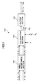
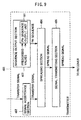
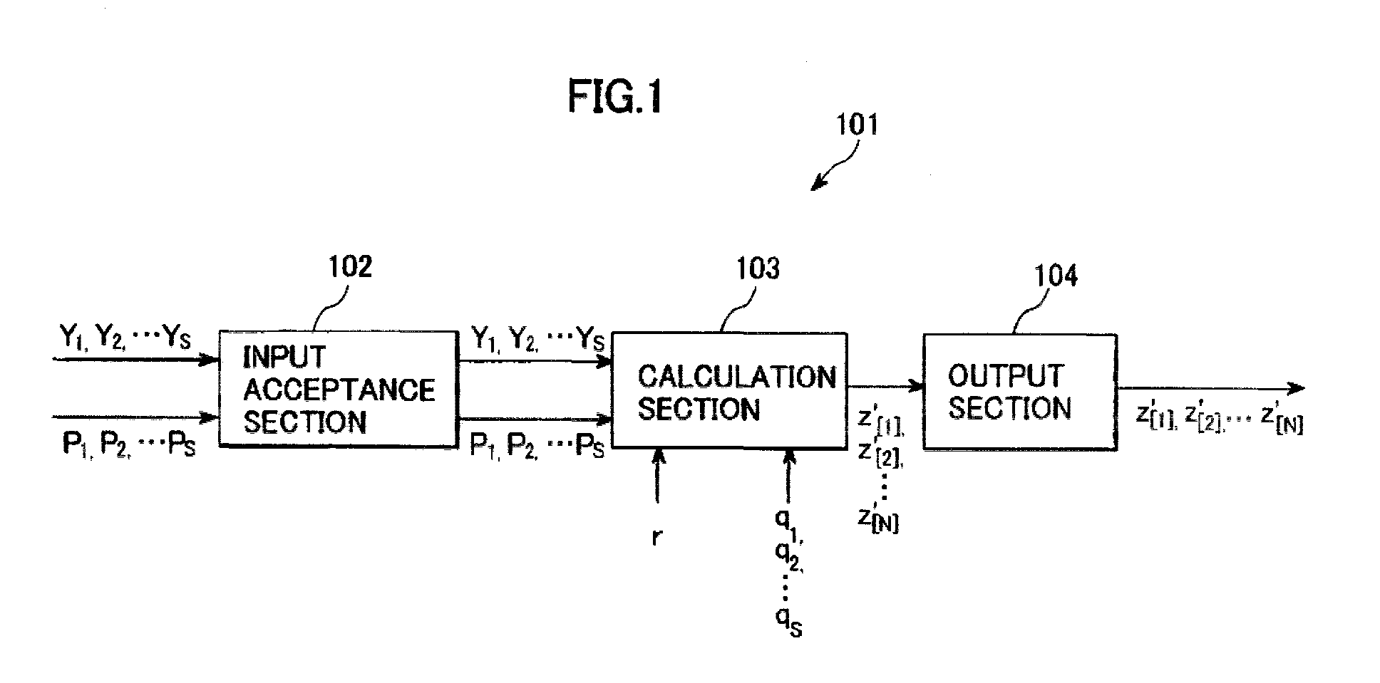
- FIG. 1 is a schematic diagram (data flow chart) showing the general configuration of a pseudo-random number sequence output unit 101 that is a first embodiment of the present invention. Explanation will now be made with reference to this figure.
- the pseudo-random sequence output unit 101 of this embodiment is equipped with an input acceptance section 102, a calculation section 103 and an output section 104. It outputs a pseudo-random number sequence of length N (1 ⁇ N) in response to s (1 ⁇ s) number of prescribed positive integers q 1 , q 2 , ..., q s , a prescribed real impulse constant r (-1 ⁇ r ⁇ 1) and a prescribed nonzero real constant C.
- the input acceptance section 102 accepts input of the following sequence initial values and integer parameters:
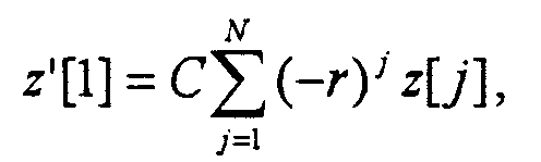
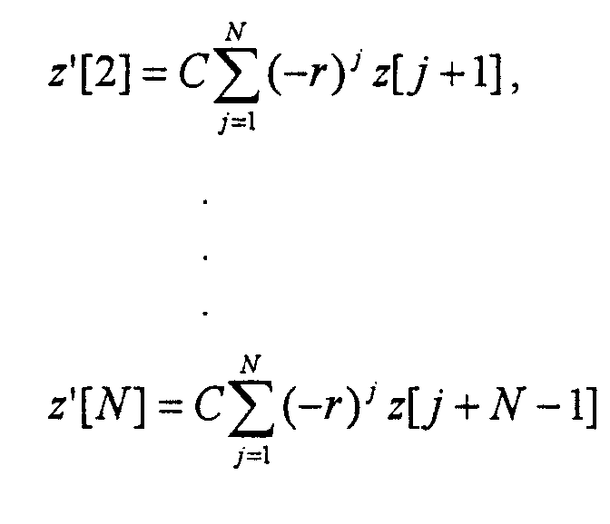
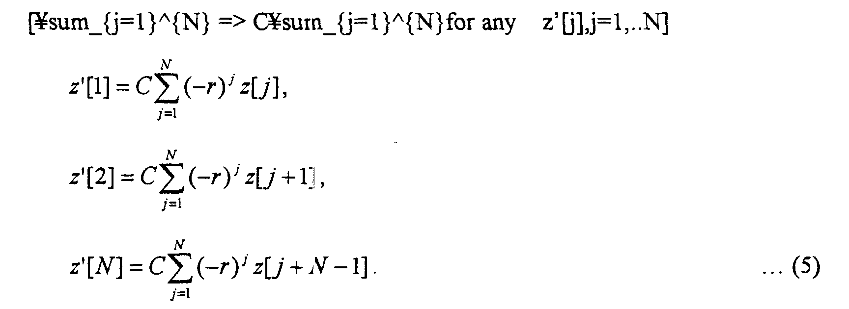
- the calculation section 103 uses the prescribed real impulse constant r, the prescribed nonzero real constant C, the sequence initial values Y 1 , Y 2 , ..., Y s whose input was accepted, the integer parameters p 1 , p 2 , ..., p s , the prescribed positive integers q 1 , q 2 , ..., q s and integers j (1 ⁇ j ⁇ s), m (1 ⁇ m ⁇ 2N-2) and n (1 ⁇ n ⁇ 2N-1) to calculate from the recurrence Formula (4) a pseudo-random number sequence z'[1], z'[2], ..., z'[N] of length N that satisfies (5).
- the output section 104 outputs the calculated pseudo-random number sequence z'[1], z'[2], ..., z'[N].
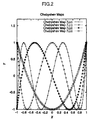
- FIG. 2 is a graph showing Chebyshev polynomials used by the calculation section 103.
- the abscissa is the x-axis and the ordinate is the y-axis.
- the calculation performed by the calculation section 103 can be implemented by polynomial arithmetic using a computer or by an adder-subtracter and multiplier in combination. It can also be implemented by floating-point arithmetic with a prescribed degree of accuracy assurance or by arithmetic using rational numbers. This will be discussed later.
- sequence initial value and integer parameter input acceptance by the input acceptance section 102 and output by the output section 104 can be conducted via registers in the computer RAM (Random Access Memory) or CPU (Central Processing Unit), and, in the case of an electronic circuit, by use of latches or the like.
- RAM Random Access Memory
- CPU Central Processing Unit
- ⁇ here labels the individual Lebesgue spectrum classes and j is a label designating the class function and j takes a countably infinite number of non-negative integers.
- Lebesgue spectrum is an orthornomal system of functions composed of an infinite number of functions.
- the label ⁇ can take an infinite number of types, (cardinality of ⁇ )
- the Lebesgue spectrum is called an "infinite Lebesgue spectrum.”
- Chebyshev chaotic dynamical system given by the quadratic or higher order Chebyshev polynomial discussed below.
- the Chebyshev chaos dynamical system is explained by R L. Alder and T. J. Rivlin in "Proc. Am. Math. Soc. 15" (1964, p794).
- correlation function (16) is given by the Lebesgue spectrum expansion coefficients as in (17). ⁇ ( B ) x ), B ( F l ( x )) ⁇ ⁇ ⁇ B 0 , B l ⁇
- This correlation function is equal to the time-average (18) because of the ergodicity.
- a sequence having a correlation function that exponentially damps in the form of (-r) 1 relative to a code shift amount 1 can thus be freely generated with respect to an arbitrary r (-1 ⁇ r ⁇ 1).
- the number of theoretical connected users can, in the case of Eq. (2), be increased 15% over the number when the spreading sequences are defined by random codes (including Gold codes and bulk codes).
- a Hilbert space L 2 can be constituted by these Chebyshev polynomials and the distribution function.
- the Chebyshev polynomials themselves are orthonormal bases possessing a complete property in the Hilbert space L 2 .
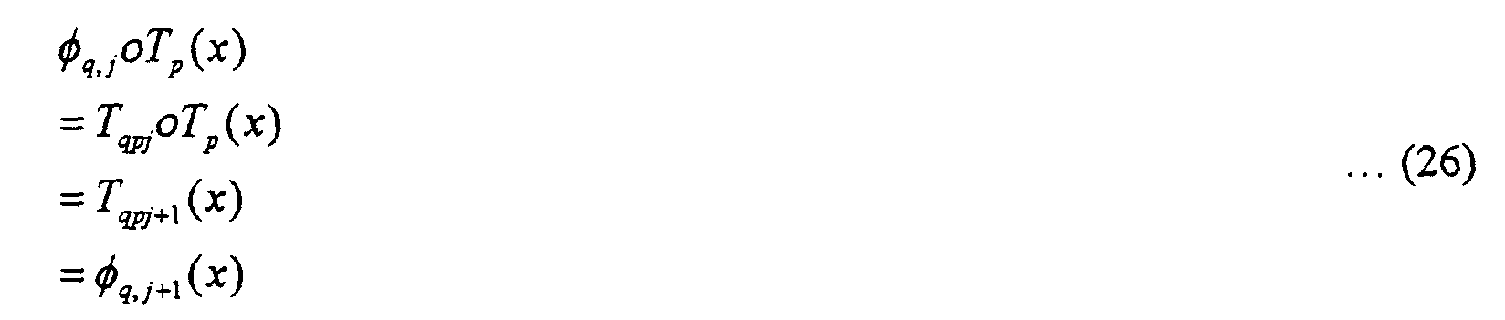
- ⁇ q , j (x) Y qpj ( x ) ( j ⁇ 0, q (mod p ) ⁇ 0)
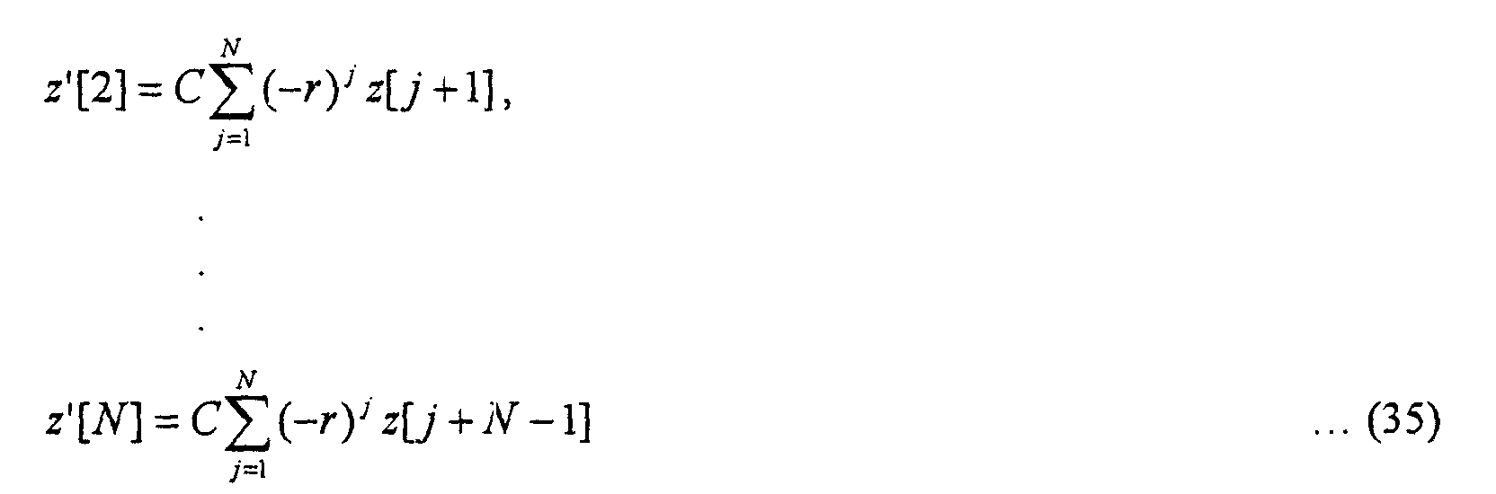
- (28) and (29) hold and it is noted that they become (30) and (31) for an arbitrary integer m (0 ⁇ m ⁇ N-1).
- FIG. 3 is a schematic diagram showing the general configuration of an FIR filter 301 constructed in this manner.
- the FIR filter 301 accepts a Chebysev chaos-type spreading code sequence X 1 , X 2 , X 3 , ... input at a terminal 305.
- the accepted Chebysev chaos-type spreading code sequence is successively delayed and distributed by series-connected delay circuits 302.
- the delay time is the chip length.
- the spreading codes successively appearing between the delay circuits 302 are amplified by amplifiers 303.
- the amplifications factors are (-r) N , (-r) N-1 , (-r) N-2 ...,(-r) 2 , (-r) 1 .
- r is optimally made the real impulse constant defined by Eq. (2). Insofar as -1 ⁇ r ⁇ 1, however, it can be used to generate spreading codes for an asynchronous CDMA telecommunication system even if it does not strictly satisfy Eq. (2).
- the signals amplified by the amplifiers 303 are summed by an adder 304 to successively output an optimum chaos-type spreading code sequence Y 1 , Y 2 , Y 3 , ....
- s number of products (34) are calculated with respect to s-dimensional real numerical values x 1 , x 2 , ..., x s generated from a Chebyshev map dynamical system determined by s number of integer parameters p 1 , p 2 , ..., p s for which q 1 mod p 1 ⁇ 0, q 2 mod p 2 ⁇ 0 ..., q s mod p s ⁇ 0 respectively hold with respect to s number of prescribed positive integers q 1 , q 2 ... q s .
- interference noise variance in asynchronous CDMA using spreading codes that are s-dimensional pseudo-random number sequences generated from a direct product chaos dynamical system can, in accordance with the foregoing theory of Mazzini et al., be represented by (3) to increase the number of users at the same bit error rate reliably by 15% relative to the case of an existing asynchronous CDMA communication system.
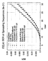
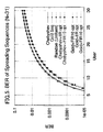
- FIGs. 4 and 5 show simulation results obtained when the pseudo-random number sequence length N was fixed to 31 and bit error rate was calculated as a function of number of users for each of the present method, white noise codes and Gold codes. The following parameters were used in the present method.
- 28 users can communicate with bit error rate 0.023 when the present Filter method is employed, while only 25 users can communicate with the same bit error rate 0.023 when the conventional spreading sequences are employed.
- FIGs. 6 and 7 show simulation results obtained when the pseudo-random number sequence length N was fixed to 127 and bit error rate was calculated as a function of number of users for each of the present method, white noise codes and Gold codes. The following parameters were used in the present method.
- 115 users can communicate with bit error rate 0.025 when the present Filter method is employed, while only 100 users can communicate with the same bit error rate 0.025 when the conventional spreading sequences are employed.
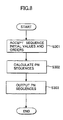
- FIG. 8 is a flowchart showing the sequence of processing steps executed by the pseudo-random sequence output unit 101, i.e., the processing of the invention pseudo-random number sequence output method.
- the pseudo-random sequence output unit 101 accepts the sequence initial values and integer parameters (orders) (step S301), uses them and the aforesaid recurrence formula to calculate a pseudo-random number sequence (step S301), and outputs the calculated pseudo-random number sequence (step S303) to complete the processing.
- the pseudo-random number sequence output method of the present invention can thus be readily implemented with a general-purpose computer, parallel computer, mobile terminal (particularly a telecommunication terminal), game device or other such data processing system.
- the pseudo-random number sequence output method of the present invention can also be readily implemented with a DSP, FPGA (Field Programmable Gate Array) or other such digital processing circuit.
- FIG. 9 is a schematic diagram showing the general configuration of a transmitter 401 according to the present invention. Elements similar to those in the foregoing figures are assigned like reference symbols. Explanation will now be made with reference to FIG. 9.
- the transmitter 401 comprises a signal acceptance section 402, sequence output section 403, a spreading section 404 and a signal transmitting section 405.
- the sequence output section 403 is equipped with the pseudo-random sequence output unit 101, which it controls.
- the signal acceptance section 402 accepts the signal to be transmitted.
- the signal for transmission is typically a voice signal.
- it is an electric digital signal.
- the optical signal can be converted to an electric signal and the electric signal accepted.
- the pseudo-random sequence output unit 101 is implemented as an optical computer, the optical signal can be accepted as it is.
- the sequence output section 403 causes the pseudo-random sequence output unit 101 provided therein to accept sequence initial values and integer parameters (orders) assigned to the transmitter 401.
- the pseudo-random sequence output unit 101 produces pseudo-random number sequences as explained earlier and the sequence output section 403 outputs them.
- Different transmitters 401 can in advance be assigned sequence initial values and integer parameters (orders) of different values.
- Many communication terminals store a production serial number, product number, approval number and the like in a ROM (Read Only Memory).
- the sequence initial values and integer parameters (orders) can similarly be stored in a ROM beforehand so that the transmitter 401 can use the same sequence initial values and integer parameters (orders) at all times.
- Another possible method is to store multiple types of sequence initial values and integer parameters (orders) in the ROM and randomly select the ones to be used at the time of each communication.
- the receiver communicating with the transmitter 401 must somehow be informed of the sequence initial values and integer parameters (orders) stored in the ROM.
- the transmitter and the receiver are paired, they can be embodied to use the same sequence initial values and integer parameters (orders).
- sequence initial values and integer parameters (orders) When multiple types of sequence initial values and integer parameters (orders) are provided, the ones used by the transmitter 401 can be determined by correlation detection as explained later. It is also possible to prepare the sequence initial values using chaos random number sequences obtained by use of a recurrence formula based on Chebyshev polynomials. In addition, as explained later, public key encryption can be used to secure sharing of sequence initial values and integer parameters (orders) between the transmitter 401 and the receiver.
- the spreading section 404 effects direct spectrum spreading by successively multiplying the signal for transmission accepted by the signal acceptance section 402 by the elements of the pseudo-random number sequences output by the sequence output section 403.
- a method will be explained here in which the value of the signal at time t is defined as s(t) and the signal s(t) is successively multiplied by the sequence elements.
- the period of "successive multiplication of the signal s(t) by the sequence elements" resulting from these elements and the chip length w is Nw.
- signal s(t) When "signal s(t) is successively multiplied by the sequence elements" starting from a prescribed time t 0 , the signal s(t) is discretized by chip length w so as to obtain the required quality. Conceivable techniques for this include, for instance, that of obtaining a value of signal s(t) for each chip length w and that of obtaining the average value of signal s(t) during chip length w . In the interest of clarity, the former method will be explained here.
- the chip length w must be long enough to enable the receiver to decode the information of the signal for transmission sufficiently at the required quality.
- An appropriate chip length can be selected by a conventional method.
- a signal that is not so degraded compared to the original signal for transmission can be obtained by successively outputting the discretized signal sequence for the selected chip length time w .
- the discretized signal can be expressed by a number sequence such as the following. s(t 0 ), s(t 0+w ), s(t 0+2w ), S(t 0+3w ), S(t 0+4w ), ...
- the signals s; (0 ⁇ i) are ones obtained by discretizing the signal for transmission at the required quality.
- the signal sequence after direct spectrum spreading of this signal sequence is s 0 z'[1], s 1 z'[2], ..., s N-1 z'[N], s N z'[1], s N+1 z'[2], ....
- Transmission of the elements of this signal sequence for the time of each chip length enables transmission of an accepted signal for transmission of prescribed time length in the same time length.
- FIG. 10 illustrates direct spectrum spreading.
- the signal for transmission 501 accepted by the signal acceptance section 402 is repeatedly multiplied by the elements of the pseudo-random number sequence 502 output by the sequence output section 403 to produce the signal 503 output by the spreading section 404.
- the signal transmitting section 405 transmits the signal 503 output by the spreading section 404.
- the transmission is, for example, conducted via an antenna in the case of a mobile phone or PHS, via a wire telephone line or wire/wireless LAN in the case of a computer network, or via an optical cable.
- FIG. 11 is a schematic diagram showing the general configuration of a receiver 601 according to the present invention. Explanation will now be made with reference to FIG. 11.
- the receiver 601 is equipped with a signal receiving section 602, a sequence output section 604 and an inverse spreading section 605.
- the signal receiving section 602 receives the signal transmitted by the transmitter 401.
- the signal receiving section 602 is constituted as an interface with, for example, an antenna, telephone line, optical fiber line or the like.
- the signal received by the signal receiving section 602 includes the signal transmitted by the transmitting party's transmitter 401 and noise.
- the receiver 601 uses pseudo-random number sequences that are identical to the pseudo-random number sequences used by the transmitter 401 for direct spectrum spreading.
- the sequence output section 604 causes the pseudo-random sequence output unit 101 to accept the sequence initial values and integer parameters (orders) used by the transmitting party's transmitter 401, thereby enabling it to output the pseudo-random number sequences.
- the sequence output section 604 of the receiver 601 in this embodiment is therefore identical to the sequence output section 403 of the transmitter 401.
- the signal for transmission accepted by the transmitting party's transmitter 401 can be despread by inverse direct spectrum spreading the signal transmitted by the transmitting party's transmitter 401, i.e., by successively multiplying it by the same pseudo-random number sequence elements. If synchronization has been established, successive multiplication of the received signal sequence s 0 z'[1], s 1 z'[2], ..., s N-1 z'[N], s N z'[1], s N+1 z'[2], ...
- Synchronization can be achieved by the correlation detection mentioned earlier or by clock sharing or any of various other methods, all of which are encompassed by the present invention.
- the receiver 601 generates a public key and a private key.
- the receiver 601 then transmits the public key to the transmitter 401.
- the transmitter 401 uses the public key to encrypt the sequence initial values and integer parameters (orders) it uses and transmits encrypted values and parameters (orders) to the receiver 601.
- the receiver 601 uses the private key to decrypt the received encrypted signal and thus obtain the sequence initial values and the integer parameters (orders).
- the chaotic key distribution method taught by the inventor's Japanese Patent Application No. 11-152063 can be used as the public-key encryption method.
- the receiver 601 can discriminate the selected pseudo-random number sequence by correlation detection. It can also use correlation detection for inverse direct spectrum spreading synchronization.
- FIG. 12 An embodiment of the invention receiver capable of correlation detection will now be explained with reference to FIG. 12. Elements in FIG. 12 similar to those in the foregoing figures are assigned like reference symbols.
- the receiver 601 of FIG. 12 is further equipped with a generating section 611 and a correlation detecting section 612.
- the generating section 611 outputs sets of sequence initial values and integer parameters (orders) selectable by the transmitter 401. Output of a single pseudo-random number sequence is also acceptable. In this case, owing to the need to select one set from among multiple sets of sequence initial values and integer parameters (orders), the correlation detecting section 612 functions to synchronize the signals.
- the sequence output section 604 In response to the sequence initial values and integer parameters (orders) generated by the generating section 611, the sequence output section 604 outputs every pseudo-random number sequence selectable by the transmitter 401.
- the correlation detecting section 612 attempts correlation detection with respect to every pseudo-random number sequence output by the sequence output section 604. Correlation detection is carried out by successively multiplying the received signal by "elements" of the pseudo-random number sequence to be checked. The correlation detection can be done using a conventional technique known to the art.
- the pseudo-random number sequences used in the present invention are excellent in correlation characteristic.
- the receiver 601 selects a different pseudo-random number sequence, therefore, the strength of the signal after multiplication is extremely weak and the correlation detection fails.
- signal synchronization can be achieved by shifting the pseudo-random number sequence offset to synchronize with the received signal.
- the inverse spreading section 605 despreads the signal for transmission by successively multiplying the signal received by the signal receiving section 602 by the reciprocals of the elements of the pseudo-random number sequence that the correlation detecting section 612 has selected and synchronized with the received signal.
- the inverse spreading section 605 successively multiplies the received signal by the "reciprocals of the elements" of the pseudo-random number sequence.
- the correlation detecting section 612 calculates correlation/cross-correlation, while the inverse spreading section 605 carries out dispreading.
- the communication system of the present invention can be configured from the transmitter 401 and the receiver 601, which receives the signal transmitted by the transmitter 401 and despreads the signal for transmission. Despreading of the signal for transmission fails when the transmitter 401 and receiver 601 use different pseudo-random number sequences.
- the pseudo-random number sequences generated according to the present invention are particularly advantageous in that they enable a greater stepwise increase in the number of code types than possible with conventional pseudo-random number sequences and, as such, are highly suitable for CDMA communication including a large number of latent users.
- the present invention provides a pseudo-random number sequence output unit, transmitter, receiver, communication system and filter unit, and a pseudo-random number sequence output method, transmission method, receiving method and filtering method that are suitable for an asynchronous CDMA communication system, and a data recording medium recorded with a program for implementing any of the foregoing.
Landscapes
- Engineering & Computer Science (AREA)
- Signal Processing (AREA)
- General Physics & Mathematics (AREA)
- Computer Networks & Wireless Communication (AREA)
- Physics & Mathematics (AREA)
- Theoretical Computer Science (AREA)
- Mathematical Optimization (AREA)
- General Engineering & Computer Science (AREA)
- Pure & Applied Mathematics (AREA)
- Mathematical Analysis (AREA)
- Computational Mathematics (AREA)
- Mobile Radio Communication Systems (AREA)
- Dc Digital Transmission (AREA)
- Image Processing (AREA)
- Signal Processing For Digital Recording And Reproducing (AREA)
- Facsimile Image Signal Circuits (AREA)
- Synchronisation In Digital Transmission Systems (AREA)
Abstract

Description

- s number of real number sequence initial values Y1, Y2, ..., Ys; provided that -1< Y1<1,-1<Y2<1, ..., -1 Ys<1,
- s number of integer parameters p1, p2, ..., ps; provided that 2≤ p1, 2≤ p2, ... 2≤ ps and for which q1 mod p1 ≠ 0, q2 mod p2 ≠ 0 .., qs mod ps ≠ 0 respectively hold with respect to the prescribed positive integers q1, q2 ... qs.











- s=1
- p=2 (corresponding to a Chebyshev generator order of 2). [<-modified]
- s=1
- p=2 (corresponding to a Chebyshev generator order of 2)
s(t0), s(t0+w), s(t0+2w), S(t0+3w), S(t0+4w), ...

s0z'[1], s1z'[2], ..., sN-1z'[N], sNz'[1], sN+1z'[2], ....
Claims (37)
- A pseudo-random number sequence output unit responsive to s (1≤s) number of prescribed positive integers q1, q2, ..., qs, a prescribed real impulse constant r (-1<r<1), a prescribed non-zero real constant C for outputting a pseudo-random number sequence of length N (1≤N), which output unit comprises:an input acceptance section that accepts input of s (1≤s) number of real number sequence initial values Y1, Y2, ..., Ys (-1< Y1<1, -1< Y2<1, ..., -1 Ys<1), and s number of integer parameters p1, p2, ..., ps (2≤ p1, 2≤ p2, ... 2≤ ps) for which q1 mod p1 ≠ 0, q2 mod p2 ≠ 0 ..., qs mod ps ≠ 0 respectively hold with respect to the prescribed positive integers q1, q2 ... qs;a calculation section that uses the prescribed real impulse constant r, the prescribed non-zero real constant C, the sequence initial values Y1, Y2, ..., Ys, the integer parameters p1, p2, ..., ps, the prescribed positive integers q1, q2, ..., qs and integers j (1≤j≤s), m (1≤m≤2N-2) and n (1≤n≤2N-1) to calculate from the recurrence formulaa pseudo-random number sequence z'[1], z'[2], ..., z'[N] of length N that satisfies
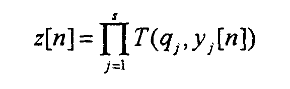
 and
and an output section that outputs the pseudo-random number sequence z'[1], z'[2], ..., z'[N].
 - The output unit according to claim 1, wherein the sequence initial values Y1, Y2, ..., Ys satisfy
- The output unit according to claim 1 or 2, wherein the prescribed real impulse constant r satisfies
- The output unit according to any of claims 1 to 3, wherein every prescribed positive integer q1, q2 ... qs is 1.
- A transmitter comprising:an input acceptance section that accepts a signal for transmission;an output unit of any of claims 1 to 4 that outputs a pseudo-random number sequence of length N;a spreading section that uses the output pseudo-random number sequence of length N as a spreading code to spectrum-spread the signal for transmission whose input was accepted; anda signal transmitting section that transmits the spectrum-spread signal.
- The transmitter according to claim 5, further comprising:a selecting section that selects sequence initial values Y1, Y2, ..., Ys and integer parameters p1, p2, ..., ps; anda parameter transmitting section that transmits the selected sequence initial values Y1, Y2, ..., Ys and integer parameters p1, p2, ..., ps;the output unit accepting input of the selected sequence initial values Y1, Y2, ..., Ys and integer parameters p1, P2, ..., ps and outputting a pseudo-random number sequence of length N.
- The transmitter according to claim 5, further comprising:a parameter receiving section that receives sequence initial values Y1, Y2, ..., Ys and integer parameters p1, p2, ..., ps;the output unit accepting input of the received sequence initial values Y1, Y2, ..., Ys and integer parameters p1, p2, ..., ps and outputting a pseudo-random number sequence of length N.
- A receiver comprising;a signal receiving section that receives a signal;an output unit of any of claims 1 to 4 that outputs a pseudo-random number sequence of length N;an inverse spreading section that uses the output pseudo-random number sequence of length N as a spreading code to inversely spectrum-spread the received signal; andan output section that outputs the inversely spectrum-spread signal as a signal for transmission.
- The receiver according to claim 8, further comprising:a selecting section that selects sequence initial values Y1, Y2, ..., Ys and integer parameters p1, p2, ..., ps; anda parameter transmitting section that transmits the selected sequence initial values Y1, Y2, ..., Ys and integer parameters p1, p2, ..., ps;the output unit accepting input of the selected sequence initial values Y1, Y2, ..., Ys and integer parameters p1, p2, ..., ps and outputting a pseudo-random number sequence of length N.
- The receiver according to claim 8, further comprising:a parameter receiving section that receives sequence initial values Y1, Y2, ..., Ys and integer parameters p1, p2, ..., ps;the output unit accepting input of the received sequence initial values Y1, Y2, ..., Ys and integer parameters p1, p2, ..., ps and outputting a pseudo-random number sequence of length N.
- A communication system comprising:the transmitter of claim 6; andthe receiver of claim 10;the receiver receiving sequence initial values Y1, Y2, ..., Ys and integer parameters p1, p2, ..., ps transmitted by the transmitter; andthe receiver also receiving a signal transmitted by the transmitter.
- A communication system comprising:the transmitter of claim 7; andthe receiver of claim 9;the transmitter receiving sequence initial values Y1, Y2, ..., Ys and integer parameters p1, p2, ..., ps transmitted by the receiver; andthe receiver receiving a signal transmitted by the transmitter.
- A filter unit for filtering a prescribed real impulse constant r (-1<r<1), the filter unit comprising:an input terminal that accepts input of an input signal of chip length D;a delay section that outputs a plurality of signals produced by delaying the input signal whose input was accepted by 0, D, 2D, 3D, ..., (N-1)D;an amplifying section that amplifies the delayed output signals (-r)(N-T)/D times, where T is the delay time, and outputs the amplified signals;an adder section that sums the output amplified signals and outputs the resulting sum signal; andan output terminal that outputs the output sum signal.
- The filter according to claim 13, wherein one or more of the delay section, amplifying section and adder section of the filter unit are constituted as an ASIC (Application Specific Integrated Circuit), a DSP (Digital Signal Processor) or an FPGA (Field Programmable Gate Array).
- A pseudo-random number sequence output method that is responsive to s (1≤s) number of prescribed positive integers q1, q2, ..., qs, a prescribed real impulse constant r (-1<r<1), and a prescribed non-zero real constant C for outputting a pseudo-random number sequence of length N (1≤N), which output method comprises:an input acceptance step that accepts s (1≤s) number of real number sequence initial values Y1, Y2, ..., Ys (-1 < Y1<1, -1< Y2<1, ..., -1 Ys<1), and s number of integer parameters p1, p2, ..., ps (2≤p1, 2≤ p2, ... 2≤ ps) for which q1 mod p1 ≠ 0, q2 mod p2 ≠ 0 ..., qs mod ps ≠ 0 respectively hold with respect to the prescribed positive integers q1, q2 ... qs;a calculation step that uses the prescribed real impulse constant r, the prescribed non-zero real constant C, the sequence initial values Y1, Y2, ..., Ys, the integer parameters p1, p2, ..., ps, the prescribed positive integers q1, q2, ..., qs and integers j (1≤j≤s), m (1≤m≤2N-2) and n (1≤n≤2N-1) to calculate from the recurrence formulaa pseudo-random number sequence z' [1], z'[2], ..., z' [N] of length N that satisfies
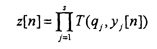
 and
and an output step that outputs the pseudo-random number sequence z' [ 1 ], z'[2], ... z'[N].
 - The output method according to the present invention according to claim 15, wherein the sequence initial values Y1, Y2, ..., Ys satisfy
- The output method according to claim 15 or 16, wherein the prescribed real impulse constant r satisfies
- The output method according to any of claims 15 to 17, wherein every prescribed positive integer qi, q2 ... qs is 1.
- A transmission method comprising:an input acceptance step that accepts input of a signal for transmission;an output step that outputs a pseudo-random number sequence of length N by the output method of any of claims 15 to 18;a spreading step that uses the output pseudo-random number sequence of length N as a spreading code to spectrum-spread the signal for transmission whose input was accepted; anda signal transmitting step that transmits the spectrum-spread signal.
- The transmission method according to claim 19, further comprising:a selecting step that selects sequence initial values Y1, Y2, ..., Ys and integer parameters p1, p2, ..., ps; anda parameter transmitting step that transmits the selected sequence initial values Y1, Y2, ..., Ys and integer parameters p1, p2, ..., ps;the output step accepting input of the selected sequence initial values Y1, Y2, ..., Ys and integer parameters p1, p2, ..., ps and outputting a pseudo-random number sequence of length N.
- The transmission method according to claim 19, further comprising:a parameter receiving step that receives sequence initial values Y1, Y2, ..., Ys and integer parameters p1, p2, ..., ps;the output step accepting input of the received sequence initial values Y1, Y2, ..., Ys and integer parameters p1, p2, ..., ps and outputting a pseudo-random number sequence of length N.
- A receiving method comprising;a signal receiving step that receives a signal;an output step that outputs a pseudo-random number sequence of length N by the output method of any of claims 15 to 18;an inverse spreading step that uses the output pseudo-random number sequence of length N as a spreading code to inversely spectrum-spread the received signal; andan output step that outputs the inversely spectrum-spread signal as a signal for transmission.
- The receiving method according to claim 22, further comprising:a selecting step that selects sequence initial values Y1, Y2, ..., Ys and integer parameters p1, p2, ..., ps; anda parameter transmitting step that transmits the selected sequence initial values Y1, Y2, ..., Ys and integer parameters p1, p2, ..., ps;.the output step accepting input of the selected sequence initial values Y1, Y2, ..., Ys and integer parameters p1, p2, ..., ps and outputting a pseudo-random number sequence of length N.
- The receiving method according to claim 22, further comprising:a parameter receiving step that receives sequence initial values Y1, Y2, ..., Ys and integer parameters p1, p2, ..., Ps;the output step accepting input of the received sequence initial values Y1, Y2, ..., Ys and integer parameters p1, p2, ..., ps and outputting a pseudo-random number sequence of length N.
- A filtering method for filtering a prescribed real impulse constant r (-1<r<1), the filtering method comprising:an input step that accepts input of an input signal of chip length D;a delaying step that outputs a plurality of signals produced by delaying the input signal whose input was accepted by 0, D, 2D, 3D, ..., (N-1)D;an amplifying step that amplifies the delayed output signals (-r)(N-T)/D times, where T is the delay time, and outputs the amplified signals;a summing step that sums the output amplified signals and outputs the resulting sum signal; andan output step that outputs the output sum signal.
- A computer-readable data recording medium recorded with a program that enables a computer to function as an output unit output unit responsive to s (1≤s) number of prescribed positive integers q1, q2, ..., qs, a prescribed real impulse constant r (-1<r<1), and a prescribed non-zero real constant C for outputting a pseudo-random number sequence of length N (1≤N), which output unit comprises:an input acceptance section that accepts input of s (1≤s) number of real number sequence initial values Y1, Y2, ..., Ys (-1< Y1<1, -1< Y2<1, ..., -1 Ys<1), and s number of integer parameters p1, p2, ..., ps (2≤ p1, 2≤p2, ... 2≤ ps) for which q1 mod p1 ≠ 0, q2 mod p2 ≠ 0 ..., qs mod ps ≠ 0 respectively hold with respect to the prescribed positive integers q1, q2 ... qs;a calculation section that uses the prescribed real impulse constant r, the prescribed non-zero real constant C, the sequence initial values Y1, Y2, ..., Ys, the integer parameters p1, p2, ..., ps, the prescribed positive integers q1, q2, ..., qs and integers j (1≤j≤s), m (1≤m≤2N-2) and n (1≤n≤2N-1) to calculate from the recurrence formulaa pseudo-random number sequence z'[1], z'[2], ..., z'[N] of length N that satisfies
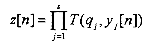
 and
and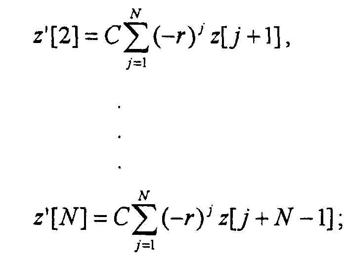 an output section that outputs the pseudo-random number sequence z'[1], z'[2], ..., z'[N]
 - The data recording medium according to claim 26, whose program operates the computer to function so that the sequence initial values Y1, Y2, ..., Ys satisfy
- The data recording medium according to claims 26 or 27, whose program operates the computer to function so that the prescribed real impulse constant r satisfies
- The data recording medium according to any of claims 26 to 28, whose program operates the computer to function so that every prescribed positive integer q1, q2 ... qs is 1.
- A computer-readable data recording medium recorded with a program that enables a computer to function as a transmitter comprising:an input acceptance section that accepts a signal for transmission;an output unit of any of claims 1 to 4 that outputs a pseudo-random number sequence of length N;a spreading section that uses the output pseudo-random number sequence of length N as a spreading code to spectrum-spread the signal for transmission whose input was accepted; anda signal transmitting section that transmits the spectrum-spread signal.
- The data recording medium according to claim 30, whose program further operates the computer to function as:a selecting section that selects sequence initial values Y1, Y2, ..., Ys and integer parameters p1, p2, ..., ps; anda parameter transmitting section that transmits the selected sequence initial values Y1, Y2, ..., Ys and integer parameters p1, p2, ..., ps; andoperates the output unit to accept input of the selected sequence initial values Y1, Y2, ..., Ys and integer parameters p1, p2, ..., ps and output a pseudo-random number sequence of length N.
- The data recording medium according to claim 30, whose program further operates the computer to function as:a parameter receiving section that receives sequence initial values Y1, Y2, ..., Ys and integer parameters p1, p2, ..., ps; andoperates the output unit to accept input of the received sequence initial values Y1, Y2, ..., Ys and integer parameters p1, p2, ..., ps and output a pseudo-random number sequence of length N.
- A computer-readable data recording medium recorded with a program that enables a computer to function as a receiver comprising:a signal receiving section that receives a signal;an output unit of any of claims 1 to 4 that outputs a pseudo-random number sequence of length N;an inverse spreading section that uses the output pseudo-random number sequence of length N as a spreading code to inversely spectrum-spread the received signal; andan output section that outputs the inversely spectrum-spread signal as a signal for transmission.
- The data recording medium according to claim 33, whose program further operates the computer to function as:a selecting section that selects sequence initial values Y1, Y2, ..., Ys and integer parameters p1, p2, ..., ps; anda parameter transmitting section that transmits the selected sequence initial values Y1, Y2, ..., Ys and integer parameters p1, p2, ..., ps; andoperates the output unit to accept input of the selected sequence initial values Y1, Y2, ..., Ys and integer parameters p1, p2, ..., ps and output a pseudo-random number sequence of length N.
- The data recording medium according to claim 33, whose program further operates the computer to function as:a parameter receiving section that receives sequence initial values Y1, Y2, ..., Ys and integer parameters p1, p2, ..., ps; andoperates the output unit to accept input of the received sequence initial values Y1, Y2, ..., Ys and integer parameters p1, p2, ..., ps and output a pseudo-random number sequence of length N.
- A computer-readable data recording medium recorded with a program that enables any of a computer, DSP (Digital Signal Processor) and FPGA (Field Programmable Gate Array) to function as filter unit for filtering a prescribed real impulse constant r (-1<r<1), the filter unit comprising:an input terminal that accepts input of an input signal of chip length D;a delay section that outputs a plurality of signals produced by delaying the input signal whose input was accepted by 0, D, 2D, 3D, ..., (N-1)D;an amplifying section that amplifies the delayed output signals (-r)(N-T)/D times, where T is the delay time, and outputs the amplified signals;an adder section that sums the output amplified signals and outputs the resulting sum signal; andan output terminal that outputs the output sum signal.
- A data recording medium according to any of claims 26 to 36, wherein the data recording medium is a compact disk, floppy disk, hard disk, magneto-optical disk, digital video disk, magnetic tape, or semiconductor memory.
Applications Claiming Priority (2)
| Application Number | Priority Date | Filing Date | Title |
|---|---|---|---|
| JP2000107047A JP3314181B2 (en) | 2000-04-07 | 2000-04-07 | Pseudo random number sequence output device, transmitting device, receiving device, communication system, filter device, pseudo random number sequence output method, transmission method, reception method, filter method, and information recording medium |
| JP2000107047 | 2000-04-07 |
Publications (2)
| Publication Number | Publication Date |
|---|---|
| EP1148644A2 true EP1148644A2 (en) | 2001-10-24 |
| EP1148644A3 EP1148644A3 (en) | 2005-10-12 |
Family
ID=18620102
Family Applications (1)
| Application Number | Title | Priority Date | Filing Date |
|---|---|---|---|
| EP01303032A Withdrawn EP1148644A3 (en) | 2000-04-07 | 2001-03-30 | Pseudo-random number sequence output unit, transmitter, receiver, communication system and filter unit, pseudo-random number sequence output method, transmission method, receiving method and filtering method, and data recording medium |
Country Status (4)
| Country | Link |
|---|---|
| US (2) | US7099366B2 (en) |
| EP (1) | EP1148644A3 (en) |
| JP (1) | JP3314181B2 (en) |
| CA (1) | CA2342542C (en) |
Cited By (2)
| Publication number | Priority date | Publication date | Assignee | Title |
|---|---|---|---|---|
| EP1401100A4 (en) * | 2001-03-26 | 2005-06-22 | Independent Administrative Institution Japan Science & Technology Agency | Filter apparatus, reception apparatus, transmission apparatus, diffusion modulation apparatus, pseudo-random number sequence output apparatus, filter method, reception method, transmission method, diffusion modulation method, pseudo-random number sequence output method, and program |
| US10452877B2 (en) | 2016-12-16 | 2019-10-22 | Assa Abloy Ab | Methods to combine and auto-configure wiegand and RS485 |
Families Citing this family (43)
| Publication number | Priority date | Publication date | Assignee | Title |
|---|---|---|---|---|
| JP3525146B2 (en) * | 2001-11-05 | 2004-05-10 | 独立行政法人 科学技術振興機構 | Random number sequence output device, random number sequence output method, program, and information recording medium |
| WO2003071766A1 (en) * | 2002-02-20 | 2003-08-28 | Xtremespectrum, Inc. | M-ary orthagonal coded communications method and system |
| US7124156B2 (en) * | 2003-01-10 | 2006-10-17 | Nec America, Inc. | Apparatus and method for immediate non-sequential state transition in a PN code generator |
| WO2004112271A1 (en) * | 2003-06-13 | 2004-12-23 | Japan Science And Technology Agency | Communication device and communication method |
| JP4371830B2 (en) * | 2004-01-27 | 2009-11-25 | 富士通株式会社 | Distortion compensation amplifier and base station |
| US7379955B1 (en) | 2004-03-16 | 2008-05-27 | The United States Of America As Represented By The Director, National Security Agency | Device for and method of generating pseudo-random sequence uniformly distributed over any range |
| US7636380B2 (en) * | 2004-05-17 | 2009-12-22 | Microsoft Corporation | Orthogonal pulse polarity modulation |
| EP1880479A1 (en) * | 2005-05-13 | 2008-01-23 | Telefonaktiebolaget LM Ericsson (publ) | A system for a fast frequency hopping radio |
| US8183980B2 (en) | 2005-08-31 | 2012-05-22 | Assa Abloy Ab | Device authentication using a unidirectional protocol |
| JP2008003976A (en) * | 2006-06-26 | 2008-01-10 | Sony Corp | MEMORY ACCESS CONTROL DEVICE AND METHOD, AND COMMUNICATION DEVICE |
| LU91292B1 (en) * | 2006-12-01 | 2008-06-02 | European Gsa | New Chaotic Spreading Codes for Galileo |
| US8312551B2 (en) * | 2007-02-15 | 2012-11-13 | Harris Corporation | Low level sequence as an anti-tamper Mechanism |
| US8611530B2 (en) | 2007-05-22 | 2013-12-17 | Harris Corporation | Encryption via induced unweighted errors |
| US8289946B2 (en) * | 2007-08-14 | 2012-10-16 | Qualcomm Incorporated | Reference signal generation in a wireless communication system |
| US8363830B2 (en) * | 2008-02-07 | 2013-01-29 | Harris Corporation | Cryptographic system configured to perform a mixed radix conversion with a priori defined statistical artifacts |
| US8320557B2 (en) * | 2008-05-08 | 2012-11-27 | Harris Corporation | Cryptographic system including a mixed radix number generator with chosen statistical artifacts |
| CN102037695A (en) * | 2008-07-16 | 2011-04-27 | 梅野健 | Communication system, transmitter, receiver and information recording medium |
| WO2010019593A1 (en) | 2008-08-11 | 2010-02-18 | Assa Abloy Ab | Secure wiegand communications |
| US8325702B2 (en) * | 2008-08-29 | 2012-12-04 | Harris Corporation | Multi-tier ad-hoc network in which at least two types of non-interfering waveforms are communicated during a timeslot |
| US8406276B2 (en) | 2008-12-29 | 2013-03-26 | Harris Corporation | Communications system employing orthogonal chaotic spreading codes |
| US8351484B2 (en) | 2008-12-29 | 2013-01-08 | Harris Corporation | Communications system employing chaotic spreading codes with static offsets |
| JP2010166536A (en) * | 2009-01-14 | 2010-07-29 | Chaosware Inc | Filtering device, transmitting device, receiving device, communication system, filtering method, transmission method, reception method, and program |
| US8457077B2 (en) | 2009-03-03 | 2013-06-04 | Harris Corporation | Communications system employing orthogonal chaotic spreading codes |
| US8509284B2 (en) | 2009-06-08 | 2013-08-13 | Harris Corporation | Symbol duration dithering for secured chaotic communications |
| US8428102B2 (en) * | 2009-06-08 | 2013-04-23 | Harris Corporation | Continuous time chaos dithering |
| US8428103B2 (en) | 2009-06-10 | 2013-04-23 | Harris Corporation | Discrete time chaos dithering |
| US8406352B2 (en) | 2009-07-01 | 2013-03-26 | Harris Corporation | Symbol estimation for chaotic spread spectrum signal |
| US8428104B2 (en) * | 2009-07-01 | 2013-04-23 | Harris Corporation | Permission-based multiple access communications systems |
| US8385385B2 (en) | 2009-07-01 | 2013-02-26 | Harris Corporation | Permission-based secure multiple access communication systems |
| US8369376B2 (en) | 2009-07-01 | 2013-02-05 | Harris Corporation | Bit error rate reduction in chaotic communications |
| US8363700B2 (en) * | 2009-07-01 | 2013-01-29 | Harris Corporation | Rake receiver for spread spectrum chaotic communications systems |
| US8379689B2 (en) | 2009-07-01 | 2013-02-19 | Harris Corporation | Anti-jam communications having selectively variable peak-to-average power ratio including a chaotic constant amplitude zero autocorrelation waveform |
| US8340295B2 (en) * | 2009-07-01 | 2012-12-25 | Harris Corporation | High-speed cryptographic system using chaotic sequences |
| US8848909B2 (en) | 2009-07-22 | 2014-09-30 | Harris Corporation | Permission-based TDMA chaotic communication systems |
| US8369377B2 (en) | 2009-07-22 | 2013-02-05 | Harris Corporation | Adaptive link communications using adaptive chaotic spread waveform |
| FR2954550A1 (en) * | 2009-12-23 | 2011-06-24 | Commissariat Energie Atomique | PROTECTION METHOD IN CONTACTLESS RADIO FREQUENCY COMMUNICATION |
| US8345725B2 (en) * | 2010-03-11 | 2013-01-01 | Harris Corporation | Hidden Markov Model detection for spread spectrum waveforms |
| CN103870238B (en) * | 2012-12-10 | 2018-03-16 | 北京普源精电科技有限公司 | Pseudo-random sequence generator and its generation method based on FPGA |
| CN103957181B (en) * | 2014-05-04 | 2017-02-15 | 电子科技大学 | Modulation and demodulation method allowing width of chip to have non-stationary characteristic |
| CN104580236B (en) * | 2015-01-21 | 2017-12-22 | 深圳市创维群欣安防科技股份有限公司 | Media stream encryption and decryption method, encryption and decryption device |
| WO2019003321A1 (en) | 2017-06-27 | 2019-01-03 | 三菱電機株式会社 | Code generation device, code generation method and code generation program |
| US10432439B2 (en) * | 2017-12-29 | 2019-10-01 | Texas Instruments Incorporated | MSK transceiver of OQPSK data |
| CN111147145B (en) * | 2019-12-06 | 2022-05-13 | 太原理工大学 | Large-key space chaotic optical communication transceiver |
Family Cites Families (13)
| Publication number | Priority date | Publication date | Assignee | Title |
|---|---|---|---|---|
| US4281411A (en) * | 1979-06-25 | 1981-07-28 | Signatron, Inc. | High speed digital communication receiver |
| US5590111A (en) * | 1990-06-29 | 1996-12-31 | Hitachi, Ltd. | Method of controlling recording of optical records |
| JPH06232957A (en) * | 1993-01-29 | 1994-08-19 | Toshiba Corp | Voice communication device |
| KR0179258B1 (en) * | 1996-01-05 | 1999-04-15 | 구자홍 | Optical disc recorder |
| JP3600037B2 (en) * | 1998-02-02 | 2004-12-08 | 株式会社リコー | Correlation peak detection circuit |
| JP3556461B2 (en) * | 1998-03-18 | 2004-08-18 | 富士通株式会社 | M-sequence phase shift coefficient calculation method |
| US6345069B1 (en) * | 1998-10-16 | 2002-02-05 | Texas Instruments Incorporated | Simplified cell search scheme for first and second stage |
| JP3396883B2 (en) | 1998-11-12 | 2003-04-14 | 独立行政法人通信総合研究所 | Optical chaos random number generator |
| JP2000310942A (en) | 1999-02-25 | 2000-11-07 | Yazaki Corp | Pseudo random number generator, stream encryption method, and stream encryption communication method |
| JP3486133B2 (en) | 1999-05-31 | 2004-01-13 | 独立行政法人通信総合研究所 | Pseudo noise sequence output system, output device, output method, and information recording medium |
| JP3234202B2 (en) * | 1999-08-19 | 2001-12-04 | 独立行政法人通信総合研究所 | Pseudo noise sequence output device, transmission device, reception device, communication system, pseudo noise sequence output method, transmission method, reception method, and information recording medium |
| US6449302B2 (en) * | 2000-04-19 | 2002-09-10 | Powerwave Technologies, Inc. | System and method for peak power reduction in spread spectrum communications systems |
| US7411997B2 (en) | 2001-03-26 | 2008-08-12 | Japan Science And Technology Corporation | Apparatus and method for filtering a spectrum spread communication |
-
2000
- 2000-04-07 JP JP2000107047A patent/JP3314181B2/en not_active Expired - Fee Related
-
2001
- 2001-03-30 US US09/820,826 patent/US7099366B2/en not_active Expired - Fee Related
- 2001-03-30 EP EP01303032A patent/EP1148644A3/en not_active Withdrawn
- 2001-03-30 CA CA 2342542 patent/CA2342542C/en not_active Expired - Fee Related
-
2006
- 2006-07-24 US US11/491,182 patent/US7466780B2/en not_active Expired - Fee Related
Cited By (2)
| Publication number | Priority date | Publication date | Assignee | Title |
|---|---|---|---|---|
| EP1401100A4 (en) * | 2001-03-26 | 2005-06-22 | Independent Administrative Institution Japan Science & Technology Agency | Filter apparatus, reception apparatus, transmission apparatus, diffusion modulation apparatus, pseudo-random number sequence output apparatus, filter method, reception method, transmission method, diffusion modulation method, pseudo-random number sequence output method, and program |
| US10452877B2 (en) | 2016-12-16 | 2019-10-22 | Assa Abloy Ab | Methods to combine and auto-configure wiegand and RS485 |
Also Published As
| Publication number | Publication date |
|---|---|
| EP1148644A3 (en) | 2005-10-12 |
| US7099366B2 (en) | 2006-08-29 |
| US7466780B2 (en) | 2008-12-16 |
| JP3314181B2 (en) | 2002-08-12 |
| CA2342542A1 (en) | 2001-10-07 |
| CA2342542C (en) | 2008-09-23 |
| JP2001292129A (en) | 2001-10-19 |
| US20020041623A1 (en) | 2002-04-11 |
| US20070098054A1 (en) | 2007-05-03 |
Similar Documents
| Publication | Publication Date | Title |
|---|---|---|
| US7099366B2 (en) | Pseudo-random number sequence output unit, transmitter, receiver, communication system and filter unit | |
| US7411997B2 (en) | Apparatus and method for filtering a spectrum spread communication | |
| KR100374623B1 (en) | Code division multiple communication method and code division multiple communication apparatus | |
| JP3234202B2 (en) | Pseudo noise sequence output device, transmission device, reception device, communication system, pseudo noise sequence output method, transmission method, reception method, and information recording medium | |
| US20110019817A1 (en) | Permission-based tdma chaotic communication systems | |
| KR20010012192A (en) | Mask generating polynomials for pseudo-random noise generators | |
| JP4210717B2 (en) | Transmission device, reception device, transmission method, reception method, program, and information recording medium | |
| Suneel | Chaotic sequences for secure CDMA | |
| US6654404B1 (en) | System, apparatus, and method for outputting pseudorandom noise sequences, and data recording medium | |
| US6813625B2 (en) | Method and device for self-clock controlled pseudo random noise (PN) sequence generation | |
| Kuznetsov et al. | Codes for multiple-access asynchronous techniques | |
| CN100454797C (en) | Despreading device and method for CDMA signal | |
| Swami et al. | A logistic-Map-Based PN Sequence for Stochastic Wireless Channels | |
| JP3799355B2 (en) | COMMUNICATION SYSTEM, TRANSMISSION DEVICE, RECEPTION DEVICE, PHASE SPREAD CODE GENERATION DEVICE, TRANSMISSION METHOD, RECEPTION METHOD, PHASE SPREAD CODE GENERATION METHOD, AND PROGRAM | |
| Setti et al. | Gaussian characterization of self-interference during synchronization of chaos based DS-CDMA systems | |
| Alshammari | A novel cryptosystem based on chaotic signals for data encryption applications and CDMA communication system | |
| KR101269849B1 (en) | Apparatus and method for generating the sequence family to spread the channel of communication system | |
| Busireddygari et al. | Binary primes sequence for cryptography and secure communication | |
| Parveen | Code selection with application to spread spectrum systems based on correlation properties | |
| Haliuk et al. | Secure multiuser communication system using chaos-based pseudorandom spreading sequences | |
| Tsuneda et al. | Design and evaluation of spreading sequences with negative auto-correlations based on chaos theory and LFSR sequences | |
| Tsuneda et al. | Performance evaluation of asynchronous DS/CDMA communications using unipolar codes | |
| Ingale et al. | Various Correlation Properties of Orthogonal Spreading Codes for CDMA Technique | |
| Rao et al. | Analysis of KMM¯ Sequences as Spreading Codes for A-CDMA Systems | |
| Kotagiri | A wireless system using random residue sequences |
Legal Events
| Date | Code | Title | Description |
|---|---|---|---|
| PUAI | Public reference made under article 153(3) epc to a published international application that has entered the european phase |
Free format text: ORIGINAL CODE: 0009012 |
|
| AK | Designated contracting states |
Kind code of ref document: A2 Designated state(s): AT BE CH CY DE DK ES FI FR GB GR IE IT LI LU MC NL PT SE TR |
|
| AX | Request for extension of the european patent |
Free format text: AL;LT;LV;MK;RO;SI |
|
| RAP1 | Party data changed (applicant data changed or rights of an application transferred) |
Owner name: COMMUNICATIONS RESEARCH LABORATORY, INDEPENDENT AD |
|
| RAP1 | Party data changed (applicant data changed or rights of an application transferred) |
Owner name: NATIONAL INSTITUTE OF INFORMATION AND COMMUNICATIO |
|
| PUAL | Search report despatched |
Free format text: ORIGINAL CODE: 0009013 |
|
| RIC1 | Information provided on ipc code assigned before grant |
Ipc: 7H 04J 13/00 B Ipc: 7H 03H 17/06 B Ipc: 7H 04B 1/69 B Ipc: 7H 03K 3/84 A |
|
| AK | Designated contracting states |
Kind code of ref document: A3 Designated state(s): AT BE CH CY DE DK ES FI FR GB GR IE IT LI LU MC NL PT SE TR |
|
| AX | Request for extension of the european patent |
Extension state: AL LT LV MK RO SI |
|
| RAP1 | Party data changed (applicant data changed or rights of an application transferred) |
Owner name: NATIONAL INSTITUTE OF INFORMATION ANDCOMMUNICATION |
|
| RAP1 | Party data changed (applicant data changed or rights of an application transferred) |
Owner name: NATIONAL INSTITUTE OF INFORMATION AND C |
|
| 17P | Request for examination filed |
Effective date: 20060317 |
|
| AKX | Designation fees paid |
Designated state(s): AT BE CH CY DE DK ES FI FR GB GR IE IT LI LU MC NL PT SE TR |
|
| 17Q | First examination report despatched |
Effective date: 20080226 |
|
| RAP1 | Party data changed (applicant data changed or rights of an application transferred) |
Owner name: UMENO, KEN Owner name: NATIONAL INSTITUTE OF INFORMATION AND C |
|
| STAA | Information on the status of an ep patent application or granted ep patent |
Free format text: STATUS: THE APPLICATION IS DEEMED TO BE WITHDRAWN |
|
| 18D | Application deemed to be withdrawn |
Effective date: 20131001 |