EP1148632A2 - FM stereo signal demodulating apparatus - Google Patents
FM stereo signal demodulating apparatus Download PDFInfo
- Publication number
- EP1148632A2 EP1148632A2 EP01108196A EP01108196A EP1148632A2 EP 1148632 A2 EP1148632 A2 EP 1148632A2 EP 01108196 A EP01108196 A EP 01108196A EP 01108196 A EP01108196 A EP 01108196A EP 1148632 A2 EP1148632 A2 EP 1148632A2
- Authority
- EP
- European Patent Office
- Prior art keywords
- output
- signal
- multiplier
- xor
- detected signal
- Prior art date
- Legal status (The legal status is an assumption and is not a legal conclusion. Google has not performed a legal analysis and makes no representation as to the accuracy of the status listed.)
- Withdrawn
Links
Images


Classifications
-
- H—ELECTRICITY
- H04—ELECTRIC COMMUNICATION TECHNIQUE
- H04H—BROADCAST COMMUNICATION
- H04H20/00—Arrangements for broadcast or for distribution combined with broadcast
- H04H20/44—Arrangements characterised by circuits or components specially adapted for broadcast
- H04H20/46—Arrangements characterised by circuits or components specially adapted for broadcast specially adapted for broadcast systems covered by groups H04H20/53-H04H20/95
- H04H20/47—Arrangements characterised by circuits or components specially adapted for broadcast specially adapted for broadcast systems covered by groups H04H20/53-H04H20/95 specially adapted for stereophonic broadcast systems
- H04H20/48—Arrangements characterised by circuits or components specially adapted for broadcast specially adapted for broadcast systems covered by groups H04H20/53-H04H20/95 specially adapted for stereophonic broadcast systems for FM stereophonic broadcast systems
-
- H—ELECTRICITY
- H04—ELECTRIC COMMUNICATION TECHNIQUE
- H04B—TRANSMISSION
- H04B1/00—Details of transmission systems, not covered by a single one of groups H04B3/00 - H04B13/00; Details of transmission systems not characterised by the medium used for transmission
- H04B1/06—Receivers
- H04B1/16—Circuits
- H04B1/1646—Circuits adapted for the reception of stereophonic signals
Definitions
- This invention relates to an FM stereo signal demodulating apparatus for demodulating an (L - R) signal multiplexed on an (L + R) signal included in an FM detected signal to acquire an L signal and an R signal.
- the FM stereo signal demodulating apparatus includes a 19K Hz bandpass filter (BPF) 1 for extracting a signal at 19 KHz from the FM detected signal, an approximated sine wave generator 30 for generating a carrier signal at 38 KHz from the signal at 19 KHz, a multiplier 31 for multiplying the FM detected signal by the carrier signal at 38 KHz to demodulate the (L-R) signal, an adder 7 and a subtracter 8.
- BPF bandpass filter
- the carrier signal at 38 KHz and the FM detected signal are multiplied so that the (L - R) signal is demodulated as shown in Fig. 6B.
- the signals shown in Figs. 6A and 6B are subjected to addition in the adder 7 to produce an L signal of 2L.
- the signals shown in Fig. 6A and 6B are also subjected to subtraction in the subtracter 8 to produce an R signal of 2R.
- the L signal and the R signal are supplied to a speaker (not shown) in which these signals are converted into an audio signal.
- the other multiplexed signal than 2L is also produced from the adder 7 and the other multiplexed signal than 2R is also produced from the subtracter 8.
- these multiplexed signals are outside an audio frequency range and hence are not produced as sound from the speaker.
- the FM stereo signal demodulating apparatus explained with reference to Fig. 4 is operated through digital signal processing and the approximated sine wave generator 30 the details of which is shown in Fig. 5 generates a signal at 38 KHz.
- the approximated sine wave generator 30 includes a 90-degree phase shifter 21 for 90-degree phase shifting the phase of the 19 KHz signal, an XOR 22 for taking an exclusive OR between the 19Hz signal and the output signal from the 90-degree phase shifter 21, another 90-degree phase shifter 23 for 90-degree shifting the phase of the output signal from the XOR 22, another XOR 24 for taking an exclusive OR between the output from the XOR 23 and the output from the 90-degree phase shifter 23, an inverter 25, still another 90-degree phase shifter 26 for 90-degree phase shifting the output signal from the inverter 25, still another XOR 27 for taking an exclusive OR between the outputs from XOR 22 and from the 90-degree phase shifter 90, a multiplier 32 for multiplying the output signal from the XOR 27 by 2 -1, and an adder 33 for adding the output from the XOR 22 and the output from the multiplier 32.
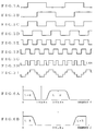
- the signal shown in Fig. 3A is fed to the approximated sine wave generator 30, the signal shown in Fig. 3B is produced from the 90-degree phase shifter 21, and the signal shown in Fig. 3C is produced from the XOR 22.
- the signal shown in Fig. 3D is produced from the 90-degree phase shifter 23, and the signal shown in Fig. 3E is produced from the XOR 24.
- the exclusive OR between the output from the XOR 22 and the output from the 90-degree phase shifter is taken by the XOR 27 so that the signal shown in Fig. 3G is produced from the XOR 27.
- the output from the XOR 27 is multiplied by 2 -1 in the multiplier 32, the signal having an amplitude of 0. 414 indicated by dotted line in Fig. 3H is produced from the multiplier 31.
- the output from the XOR 22 and output from the multiplier 32 are added in the adder 33 so that the signal shown in Fig. 3I is produced from the adder 33.
- the signal shown in Fig. 3I has a period of 38 KHz that is twice as long as that of the 19 KHz signal and an amplitude approximated to a sine wave.
- the multiplier 31 multiplies the m bit signal from the approximated sine wave generator 30 and the FM-detected n bit signal.
- the multiplication of m bits x n bits is carried out by adding m bits by n-times. This takes a relatively long time. In order to complete the multiplication within a prescribed time, the multiplier which can be operated at a high speed is required. This leads to an increase in the production cost.
- An object of this invention is to provide an FM stereo signal demodulating apparatus and method which can be operated at a low speed.
- an FM stereo signal demodulating apparatus comprising:
- the third multiplier makes multiplication by 2 -1 instead of that by 2 -1.
- the first multiplier is adapted so that if the output from the first logic circuits is "1", the FM detected signal is passed, whereas if the output from the first logic circuits is "0", the FM detected signal is inverted, or otherwise if the output from the first logic circuits is "0", the FM detected signal is passed, whereas if the output from the first logic circuits is "1", the FM detected signal is inverted.
- the second multiplier is adapted so that if the output from the third logic means is "1", the FM detected signal is passed, whereas if the output from the first logic circuit is "0", the FM detected signal is inverted, or otherwise if the output from the third logic circuit is "0", the FM detected signal is passed, whereas if the output from the third logic means is "1", the FM detected signal is inverted.
- the 2 bits produced from the approximated sine wave source and the FM detected signal are individually multiplied and thereafter the multiplied results are added. Therefore, the multiplication is carried out as multiplication by 1 bit so that the multiplexed signal can be easily demodulated.
- Fig. 1 shows the configuration of a an FM stereo signal demodulating apparatus according to an embodiment of this invention
- Fig. 2 shows the configuration of an approximated sine wave source generator in the embodiment.
- the FM stereo signal demodulating apparatus includes a 19K Hz bandpass filter (BPF) 1 for extracting a signal at 19 KHz from the FM detected signal, an approximated sine wave source generator 2, multipliers 3 and 4, a multiplier 5 for multiplication by 2 -1, adders 6 and 7 and a subtracter 8.
- BPF bandpass filter
- the approximated sine wave source generator 2 includes a first 90-degree phase shifter 21, a first XOR 22, a second 90-degree phase shifter 23, a second XOR 24, an inverter 25, a third 90-degree phase shifter 26 and a third XOR 27.
- the multiplier 32 and adder 33 are removed from the conventional approximated sine wave generator 30 shown in Fig. 5. Therefore, the outputs from the XOR 22 and XOR 27 are produced as output signals (Figs. 3C and 3G) from the approximated sine wave generator 2, respectively.
- the output from the XOR 22 in the approximated sine wave source generator 2 and the FM detected signal are multiplied in a multiplier 3.
- the FM detected signal is passed, whereas if the output from the XOR 22 is "0", the FM detected signal is inverted. Otherwise, if the output from the XOR 22 is "0", the FM detected signal may be passed, whereas if the output from the XOR 22 is "1", the FM detected signal may be inverted.
- the output from the XOR 27 in the approximated sine source generator 2 and the FM detected signal are multiplied in a multiplier 4, and the output from the multiplier 4 is further multiplied by 2 -1. Specifically, if the output from the XOR 27 is "1", the FM detected signal is passed, and the output from the XOR 27 is "0", the FM detected signal is inverted. Otherwise, if the output from the XOR 27 is "0", the FM detected signal may be passed, and the output from the XOR 27 is "1", the FM detected signal may be inverted. Further, the output from the multiplier 4 is multiplied by 2 -1.
- the output from the multiplier 3 and the output from the multiplier 5 are added in an adder 6.
- the output from the adder 6 is supplied to an adder 7 and a subtracter 8.
- the output from the adder 6 and the FM detected signal are subjected to addition in the adder 7 to demodulate the L-signal. Further, the output from the adder 6 and the FM detected signal are subjected to subtraction in the subtracter 8 to demodulate the R-signal.
- the outputs from the XOR 22 and XOR 27 constitute "1" bit representative of "1" or "0", respectively so that the this 1 bit and the FM detected signal are multiplied in the multipliers 3 and 4, respectively.
- the multiplied result are added in the adder 6.
- the conventional multiplication of m bit x bit can be carried out using two n x 1-bit multipliers 3 and 4 so that it can be easily realized.
- the multipliers 3 and 5 can be constructed so that if the output from the approximated sine wave generator 2 is "1" (or “0"), the FM detected signal is passed whereas if the output thereof is "0" (or “1"), the FM detected signal is passed.
- the multiplication by 2 -1 was made in the multiplier 5.
- the multiplication by 2 -1 may be made for the approximation to the sine wave. In this way, the digital value which is produced from the multiplier 4 can be multiplied by 1 bit shifting in the multiplier 5.
- the multiplication by power of 2 such as 2 -1 ⁇ 2 -1 - 2 -4 - 2 -6 - 2 -7 may be carried out for the purpose of the above approximation.
Landscapes
- Engineering & Computer Science (AREA)
- Signal Processing (AREA)
- Computer Networks & Wireless Communication (AREA)
- Stereo-Broadcasting Methods (AREA)
- Digital Transmission Methods That Use Modulated Carrier Waves (AREA)
Abstract
Description
Claims (8)
- An FM stereo signal demodulating apparatus comprising:a filter for extracting a 19 Hz signal from an FM detected signal;a first phase-shifter for phase-shifting the 19 Hz signal by 90 degree;first logic circuits for taking an exclusive OR between an output from said first phase-shifter and the 19 KHz signal;a second phase-shifter for phase-shifting by 90 degree an output signal from said first logic means;second logic circuits for taking an exclusive OR between an output from said first logic means and an output from said second logic means;an inverter for inverting an output from said second logic means;a third phase-shifter for phase-shifting an output signal from said inverting means;third logic circuits for taking an exclusive OR between an output from said third phase-shifter and an output from said first logic circuits;a first multiplier for multiplying an output from said first logic circuit and said FM detected signal;a second multiplier for multiplying an output from said third logic circuit and said FM detected signal;a third multiplier for multiplying an output from said second multiplier bya first adder for adding an output from said first multiplying means and an output from said third multiplier;a second adder for adding said FM detected signal and an output from said first adder; anda subtracter for subtracting an output from said first adder from said FM detected signal.
- An FM stereo signal demodulating apparatus according to claim 1, wherein said third multiplier makes multiplication by 2-1 instead of that by
- An FM stereo signal demodulating apparatus according to claim 1, wherein said first multiplier is adapted so that if the output from said first logic circuits is "1", said FM detected signal is passed, whereas if the output from said first logic circuits is "0", said FM detected signal is inverted,
- An FM stereo signal demodulating apparatus according to claim 1, wherein said first multiplier is adapted so that if the output from said first logic circuits is "0", said FM detected signal is passed, whereas if the output from said first logic circuits is "1", said FM detected signal is inverted.
- An FM stereo signal demodulating apparatus according to claim 2, wherein said first multiplier is adapted so that if the output from said first logic circuits is "1", said FM detected signal is passed, whereas if the output from said first logic circuits is "0", said FM detected signal is inverted,
- An FM stereo signal demodulating apparatus according to claim 2, wherein said first multiplier is adapted so that if the output from said first logic circuits is "0", said FM detected signal is passed, whereas if the output from said first logic circuits is "1", said FM detected signal is inverted.
- An FM stereo signal demodulating apparatus according to claims 1 to 6, wherein said second multiplier is adapted so that if the output from said third logic means is "1", said FM detected signal is passed, whereas if the output from said first logic circuits is "0", said FM detected signal is inverted.
- An FM stereo signal demodulating apparatus according to claims 1 to 6, wherein said second multiplier is adapted so that if the output from said third logic circuits is "0", said FM detected signal is passed, whereas if the output from said third logic circuits is "1", said FM detected signal is inverted.
Applications Claiming Priority (2)
| Application Number | Priority Date | Filing Date | Title |
|---|---|---|---|
| JP2000099765 | 2000-03-31 | ||
| JP2000099765A JP2001285226A (en) | 2000-03-31 | 2000-03-31 | Fm stereo signal demodulator |
Publications (2)
| Publication Number | Publication Date |
|---|---|
| EP1148632A2 true EP1148632A2 (en) | 2001-10-24 |
| EP1148632A3 EP1148632A3 (en) | 2003-01-29 |
Family
ID=18614071
Family Applications (1)
| Application Number | Title | Priority Date | Filing Date |
|---|---|---|---|
| EP01108196A Withdrawn EP1148632A3 (en) | 2000-03-31 | 2001-03-30 | FM stereo signal demodulating apparatus |
Country Status (3)
| Country | Link |
|---|---|
| US (1) | US6714651B2 (en) |
| EP (1) | EP1148632A3 (en) |
| JP (1) | JP2001285226A (en) |
Families Citing this family (4)
| Publication number | Priority date | Publication date | Assignee | Title |
|---|---|---|---|---|
| US7406302B1 (en) | 2003-12-15 | 2008-07-29 | Marvell International, Inc. | Digital FM stereo receiver architecture |
| EP1852988A1 (en) * | 2005-01-24 | 2007-11-07 | Pioneer Corporation | Subcarrier signal generator and multiplexed signal demodulator |
| WO2007066672A1 (en) * | 2005-12-06 | 2007-06-14 | Rohm Co., Ltd. | Frequency modulator and fm transmission circuit using the same |
| US9184961B2 (en) | 2011-07-25 | 2015-11-10 | Ibiquity Digital Corporation | FM analog demodulator compatible with IBOC signals |
Family Cites Families (4)
| Publication number | Priority date | Publication date | Assignee | Title |
|---|---|---|---|---|
| US4506376A (en) * | 1981-12-17 | 1985-03-19 | Pioneer Electronic Corporation | Subcarrier signal generator for use in stereo tuners |
| US4651107A (en) * | 1984-01-11 | 1987-03-17 | Nec Corporation | Demodulator for digital FM signals |
| DE4303387A1 (en) * | 1993-02-05 | 1994-08-11 | Blaupunkt Werke Gmbh | Circuit arrangement for decoding a multiplex signal in a stereo radio receiver |
| JP3003600B2 (en) * | 1996-11-20 | 2000-01-31 | 日本電気株式会社 | FM demodulation circuit |
-
2000
- 2000-03-31 JP JP2000099765A patent/JP2001285226A/en active Pending
-
2001
- 2001-03-30 EP EP01108196A patent/EP1148632A3/en not_active Withdrawn
- 2001-04-02 US US09/822,484 patent/US6714651B2/en not_active Expired - Fee Related
Also Published As
| Publication number | Publication date |
|---|---|
| US6714651B2 (en) | 2004-03-30 |
| EP1148632A3 (en) | 2003-01-29 |
| US20010026621A1 (en) | 2001-10-04 |
| JP2001285226A (en) | 2001-10-12 |
Similar Documents
| Publication | Publication Date | Title |
|---|---|---|
| JP3647894B2 (en) | Intermediate frequency FM receiver using analog oversampling to increase signal bandwidth | |
| JPH069348B2 (en) | Spread spectrum communication system | |
| CN105791179B (en) | Sampling frequency offset compensation device and method | |
| JPS583424B2 (en) | Stereo Fukugo Shingo Hatsuseihouhou Oyobi Souchi | |
| JP2005295378A (en) | Ultrasonic digital communication device | |
| US6714651B2 (en) | FM stereo signal demoudulating apparatus and method | |
| CN101577851B (en) | Method for improving stereo crosstalk | |
| EP1094627A1 (en) | Method and device to retrieve RDS information | |
| RU2113062C1 (en) | Reference-wave shaper for detecting phase-keyed signals | |
| JPH06318921A (en) | Circuit device for decoding multiplex signal in stereophonic broadcasting receiver | |
| JPS6256705B2 (en) | ||
| JPH07202574A (en) | Demodulator | |
| JP2009246430A (en) | Radio communication device and method of processing radio communication device | |
| JP2675553B2 (en) | Digital tuner | |
| KR950003359B1 (en) | Demodulator fit for high speed processing | |
| JP2001333034A (en) | Device for demodulating multiplexed signal | |
| US3965302A (en) | Stereo signal demodulator in a four-channel stereo broadcast receiver | |
| JP2893496B2 (en) | Data transmission circuit | |
| JP4275657B2 (en) | SSB signal receiver | |
| SU788428A1 (en) | Device for quasicoherent demodulation of complex phase-manipulated pseudorandom signals | |
| JP4070797B2 (en) | Subcarrier signal generator and multiplexed signal demodulator | |
| WO2002056585A1 (en) | Receiver | |
| JP3645208B2 (en) | Medium-wave stereo broadcast receiving circuit | |
| JP3571520B2 (en) | AM stereo broadcast transmitter | |
| JP2002290868A (en) | Frequency conversion circuit, demodulation circuit and television receiver |
Legal Events
| Date | Code | Title | Description |
|---|---|---|---|
| PUAI | Public reference made under article 153(3) epc to a published international application that has entered the european phase |
Free format text: ORIGINAL CODE: 0009012 |
|
| AK | Designated contracting states |
Kind code of ref document: A2 Designated state(s): AT BE CH CY DE DK ES FI FR GB GR IE IT LI LU MC NL PT SE TR |
|
| AX | Request for extension of the european patent |
Free format text: AL;LT;LV;MK;RO;SI |
|
| PUAL | Search report despatched |
Free format text: ORIGINAL CODE: 0009013 |
|
| AK | Designated contracting states |
Designated state(s): AT BE CH CY DE DK ES FI FR GB GR IE IT LI LU MC NL PT SE TR |
|
| AX | Request for extension of the european patent |
Extension state: AL LT LV MK RO SI |
|
| RIC1 | Information provided on ipc code assigned before grant |
Ipc: 7H 04H 5/00 B Ipc: 7H 03D 1/22 A |
|
| 17P | Request for examination filed |
Effective date: 20030122 |
|
| 17Q | First examination report despatched |
Effective date: 20030422 |
|
| AKX | Designation fees paid |
Designated state(s): DE FR GB |
|
| STAA | Information on the status of an ep patent application or granted ep patent |
Free format text: STATUS: THE APPLICATION IS DEEMED TO BE WITHDRAWN |
|
| 18D | Application deemed to be withdrawn |
Effective date: 20040103 |