EP1148479A2 - Optical recording medium, optical recording method, optical reproducing method, and optical recording/reproducing device - Google Patents
Optical recording medium, optical recording method, optical reproducing method, and optical recording/reproducing device Download PDFInfo
- Publication number
- EP1148479A2 EP1148479A2 EP01108178A EP01108178A EP1148479A2 EP 1148479 A2 EP1148479 A2 EP 1148479A2 EP 01108178 A EP01108178 A EP 01108178A EP 01108178 A EP01108178 A EP 01108178A EP 1148479 A2 EP1148479 A2 EP 1148479A2
- Authority
- EP
- European Patent Office
- Prior art keywords
- recording
- reproducing
- sensitivity
- optical
- optical recording
- Prior art date
- Legal status (The legal status is an assumption and is not a legal conclusion. Google has not performed a legal analysis and makes no representation as to the accuracy of the status listed.)
- Ceased
Links
Images



Classifications
-
- G—PHYSICS
- G11—INFORMATION STORAGE
- G11B—INFORMATION STORAGE BASED ON RELATIVE MOVEMENT BETWEEN RECORD CARRIER AND TRANSDUCER
- G11B7/00—Recording or reproducing by optical means, e.g. recording using a thermal beam of optical radiation by modifying optical properties or the physical structure, reproducing using an optical beam at lower power by sensing optical properties; Record carriers therefor
- G11B7/12—Heads, e.g. forming of the optical beam spot or modulation of the optical beam
- G11B7/125—Optical beam sources therefor, e.g. laser control circuitry specially adapted for optical storage devices; Modulators, e.g. means for controlling the size or intensity of optical spots or optical traces
- G11B7/126—Circuits, methods or arrangements for laser control or stabilisation
-
- G—PHYSICS
- G11—INFORMATION STORAGE
- G11B—INFORMATION STORAGE BASED ON RELATIVE MOVEMENT BETWEEN RECORD CARRIER AND TRANSDUCER
- G11B11/00—Recording on or reproducing from the same record carrier wherein for these two operations the methods are covered by different main groups of groups G11B3/00 - G11B7/00 or by different subgroups of group G11B9/00; Record carriers therefor
- G11B11/10—Recording on or reproducing from the same record carrier wherein for these two operations the methods are covered by different main groups of groups G11B3/00 - G11B7/00 or by different subgroups of group G11B9/00; Record carriers therefor using recording by magnetic means or other means for magnetisation or demagnetisation of a record carrier, e.g. light induced spin magnetisation; Demagnetisation by thermal or stress means in the presence or not of an orienting magnetic field
- G11B11/105—Recording on or reproducing from the same record carrier wherein for these two operations the methods are covered by different main groups of groups G11B3/00 - G11B7/00 or by different subgroups of group G11B9/00; Record carriers therefor using recording by magnetic means or other means for magnetisation or demagnetisation of a record carrier, e.g. light induced spin magnetisation; Demagnetisation by thermal or stress means in the presence or not of an orienting magnetic field using a beam of light or a magnetic field for recording by change of magnetisation and a beam of light for reproducing, i.e. magneto-optical, e.g. light-induced thermomagnetic recording, spin magnetisation recording, Kerr or Faraday effect reproducing
- G11B11/10582—Record carriers characterised by the selection of the material or by the structure or form
- G11B11/10584—Record carriers characterised by the selection of the material or by the structure or form characterised by the form, e.g. comprising mechanical protection elements
-
- G—PHYSICS
- G11—INFORMATION STORAGE
- G11B—INFORMATION STORAGE BASED ON RELATIVE MOVEMENT BETWEEN RECORD CARRIER AND TRANSDUCER
- G11B11/00—Recording on or reproducing from the same record carrier wherein for these two operations the methods are covered by different main groups of groups G11B3/00 - G11B7/00 or by different subgroups of group G11B9/00; Record carriers therefor
- G11B11/10—Recording on or reproducing from the same record carrier wherein for these two operations the methods are covered by different main groups of groups G11B3/00 - G11B7/00 or by different subgroups of group G11B9/00; Record carriers therefor using recording by magnetic means or other means for magnetisation or demagnetisation of a record carrier, e.g. light induced spin magnetisation; Demagnetisation by thermal or stress means in the presence or not of an orienting magnetic field
- G11B11/105—Recording on or reproducing from the same record carrier wherein for these two operations the methods are covered by different main groups of groups G11B3/00 - G11B7/00 or by different subgroups of group G11B9/00; Record carriers therefor using recording by magnetic means or other means for magnetisation or demagnetisation of a record carrier, e.g. light induced spin magnetisation; Demagnetisation by thermal or stress means in the presence or not of an orienting magnetic field using a beam of light or a magnetic field for recording by change of magnetisation and a beam of light for reproducing, i.e. magneto-optical, e.g. light-induced thermomagnetic recording, spin magnetisation recording, Kerr or Faraday effect reproducing
- G11B11/10595—Control of operating function
-
- G—PHYSICS
- G11—INFORMATION STORAGE
- G11B—INFORMATION STORAGE BASED ON RELATIVE MOVEMENT BETWEEN RECORD CARRIER AND TRANSDUCER
- G11B7/00—Recording or reproducing by optical means, e.g. recording using a thermal beam of optical radiation by modifying optical properties or the physical structure, reproducing using an optical beam at lower power by sensing optical properties; Record carriers therefor
- G11B7/007—Arrangement of the information on the record carrier, e.g. form of tracks, actual track shape, e.g. wobbled, or cross-section, e.g. v-shaped; Sequential information structures, e.g. sectoring or header formats within a track
-
- G—PHYSICS
- G11—INFORMATION STORAGE
- G11B—INFORMATION STORAGE BASED ON RELATIVE MOVEMENT BETWEEN RECORD CARRIER AND TRANSDUCER
- G11B7/00—Recording or reproducing by optical means, e.g. recording using a thermal beam of optical radiation by modifying optical properties or the physical structure, reproducing using an optical beam at lower power by sensing optical properties; Record carriers therefor
- G11B7/24—Record carriers characterised by shape, structure or physical properties, or by the selection of the material
Definitions
- the present invention relates to an optical recording medium having a writable recording layer having a maker recording area on an optical recording medium substrate, an optical recording method, an optical reproducing method, and an optical recording/reproducing device therefor.
- an optical medium such as an optical disk represented by, e.g., a mini disk (MD), for example, a so-called WO (Write Once) type optical recording medium on which data can be recorded once or a so-called RW (Rewritable) type optical recording medium on which data is rewritable, on a substrate molded by, e.g., an injection mold, in the molding, in a predetermined region of the substrate, a so-called premastered area in which information of a design center value of an illumination light power at, e.g., a standard temperature, i.e., a standard value, in optical recording or/and optical reproducing of the optical recording medium is written by pits or wobbled grooves is formed.
- WO Write Once
- RW Rewritable
- optical recording or/and optical reproducing of the optical recording medium the information in the premastered area described above is loaded on a drive device for the optical recording medium, optical recording or/and optical reproducing is performed by using a value corrected by a set temperature as an optimum power. For this reason, a difference between the sensitivities of optical recording media of different makers is corrected.
- recording power sensitivities will be exemplified.
- a variation of sensitivities of an outer peripheral portion and an inner peripheral portion of a disk-like optical recording medium in the radial direction, a variation of optical recording media in a manufacturing lot, and a variation of manufacturing lots are known.
- a variation of disks e.g., a variation of recording power sensitivities in the inner and outer peripheries or the like cannot be attempted to be sufficiently reduced in the manufacturing processes. For this reason, under the present circumstances, a variation caused by manufacturing cannot be easily suppressed within a small margin.
- the present invention is to provide an optical recording medium, an optical recording method, an optical reproducing method, and an optical recording/reproducing device which attempt to solve these problems, i.e., which can increase a yield and which can stably perform optical recording and optical reproducing under optimum conditions.
- an optical recording medium has a writable recording layer on a substrate and has a maker recording area on which a maker performs recording on the recording layer, and individual drive control information of the optical recording medium is recorded in the maker recording area.
- the drive control information is an individual variation in optical recording media, for example, all or part of respective information on a recording sensitivity, a reproducing sensitivity, temperature dependency of a recording sensitivity, temperature dependency of a reproducing sensitivity, linear speed dependency of a recording sensitivity, linear speed dependency of a reproducing sensitivity, recording magnetic field sensitivity, reproducing magnetic field sensitivity, an optimum resolution, optimum asymmetry, a change in sensitivity caused by repetitive recording, and a change in sensitivity caused by repetitive reproducing.
- an optical recording method for an optical recording medium having a writable recording layer on a substrate and having a maker recording area and a user recording area formed on the recording layer individual drive control information of the optical recording medium is recorded in the maker recording area, and the optical recording method comprises the steps of controlling a drive circuit based on the drive control information and performing optical recording in the user area by the drive circuit.
- an optical reproducing method for an optical recording medium having a writable recording layer on a substrate and having a maker recording area and a user recording area formed on the recording layer individual drive control information of the optical recording medium is recorded in the maker recording area, and the optical reproducing method comprises the steps of controlling a drive circuit on the basis of the drive control information and performing optical reproducing from the user area by the drive circuit.
- an optical recording/reproducing device for an optical recording medium having, on a substrate, a premastered recording area written by a pattern obtained by molding when the substrate is molded, and having a writable recording layer on the substrate, a maker recording area and a user recording area being formed on the recording layer, using an optical recording medium in which individual drive control information of the optical recording medium is recorded in the maker recording area includes a recording/reproducing laser, an automatic power control circuit of the laser, an emission power monitor for the laser, a premastered signal detection unit for detecting a premastered signal in the premastered area of the optical recording medium, a maker signal detection signal for detecting a maker recording signal of the maker recording area, a temperature sensor, a control circuit, and an error detection unit, and a memory.
- control circuit By the control circuit, the error detection unit, and the memory, on the basis of error-free signals of the premastered signal and the maker recording signal, a correction value to a standard value is obtained, a control signal subjected to temperature correction on the basis of temperature information obtained from the temperature sensor is obtained, the control signal and a monitor signal obtained by the emission power monitor of the laser are guided to the automatic power control circuit, and optical recording and optical reproducing to the optical recording medium are performed while the emission power of the laser is automatically controlled by the automatic power control circuit.
- the present invention not only information recorded based on a standard value serving as, e.g., a design center, determined when the substrate of the optical recording medium is molded, i.e., but also the individual information of the optical recording medium, i.e., information based on a variation of optical recording media are recorded in the maker recording area, so that optical recording and optical reproducing can be performed on the basis of the information. For this reason, when the respective optical recording media are shifted from the standard value recorded in the premastered by a regulation or more, on the basis of the information recorded in the maker recording area, excellent optical recording or reproducing can be performed.
- FIG. 1 shows a schematic plan view of an example of an embodiment of a disk-type optical recording medium, e.g., a mini disk (MD) according to the present invention.
- a disk-type optical recording medium e.g., a mini disk (MD) according to the present invention.
- the optical recording medium according to the present invention is not limited to a disk-type optical recording medium, as a matter of course.
- a writable recording layer 2 is formed on a substrate 1 formed by injection molding obtained by, e.g., polycarbonate (PC).
- PC polycarbonate
- This recording layer 2 has a user recording area 3 on which recording is performed by a user.
- a maker recording area 4 on which a maker performs recording is formed on the inner peripheral side of the recording area 3.
- a premastered area 5 in which information obtained by pits or wobbling or the like molded, i.e., written when the substrate 1 is molded is formed on the inner peripheral side of the maker recording area 4.
- an optical recording medium of this type e.g., a recording laser beam power selected by a maker
- a design center value of a reproducing laser beam power i.e., standard value information are recorded.
- a magnetic metal plate 7 is mounted on the central side through an inner peripheral invalid area 6.
- the magnetic metal plate 7 is magnetically absorbed on a disk loading unit of a drive device, so that the optical recording medium is loaded into the drive device.
- optical recording medium In the optical recording medium according to the present invention, individual drive control information of the optical recording medium is recorded in the maker recording area 4.
- the sensitivity information of the optical recording medium in which a sensitivity characteristic is shifted from, e.g., a sensitivity standard value written in the premastered area 5 of the substrate 1 by a standard margin or more is recorded in the maker recording area 4.
- the recording information to the maker recording area 4 is paired with the information of the premastered area 5, i.e., cooperates with the information of the premastered area 5 to obtain desired information, so that the number of bits of the information to the maker recording area 4 can be reduced.
- the sensitivity, the optimum recording power or a reproducing power is not recorded as an absolute numeral value.
- the information of the difference between the sensitivity and the standard value of the premastered area 5 written in the substrate 1 is recorded in the maker recording area 4, so that the number of bits of the information related to the sensitivity to the maker recording area 4 can be reduced.
- the same information can be repeatedly recorded on a plurality of portions in the maker recording area 4.
- the pieces of information in recording and reproducing on/from the optical recording medium, by reading the pieces of same information, it is decided whether the information is erroneous information or not, i.e., the pieces of information include pieces of erroneous information generated by recording errors or the like.
- the pieces of information include erroneous information
- the next best method of operating the drive device by information written in the premastered area 5 can be employed.
- pieces of information of n zones e.g., several ten zones in the radial direction of the disk-recording medium can be recorded.
- a difference between the pieces of information and the standard value written in the premastered area 5 is recorded.
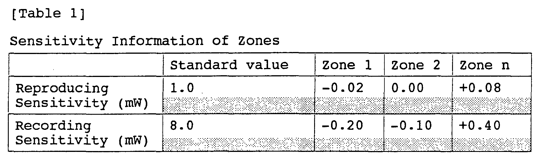
- a reproducing sensitivity and a recording sensitivity i.e., the power of a reproducing laser beam and the power of a recording laser beam, as illustrated in Table 1, when the standard values written in the premastered area 5 are 1.0 mW and 8.0 mW, as pieces of information related to zones 1 to n, the information of the differences between the pieces of the information and the standard values are written.
- the pieces of information related to the zones 1 to n can be obtained by measuring the characteristics of the zones related to a plurality of optical recording media randomly sampled from, e.g., the same manufacturing lot to calculate average values of the respective zones.
- an optical recording medium such as an MD
- the temperature dependency of a recording sensitivity is regulated, and reproducing characteristic is sensitive to a temperature as in a super-resolution optical recording medium. For this reason, in these optical recording media, changes in sensitivity caused by a recording temperature and a reproducing temperature must be also regulated.
- This super-resolution optical recording medium in reading information from the optical recording medium, uses a temperature distribution in an irradiated reproducing laser beam spot.
- recording information i.e., magnetization
- parts of information bits of a plurality of information bits in the optical spot are selectively read, or the temperature distribution in the spot of a similar reproduced laser beam makes it possible to erase parts of the information bits and to reproduce only parts of the information bits, so that information bits each having a size equal to or smaller than the optical spot can be read.
- a resolution which is equal to or lower than an optical limit can be realized. Therefore, in the optical recording medium, the reproducing characteristic is sensitive to a temperature.
- a record of pieces of information of a recording sensitivity, a reproducing sensitivity, temperature dependency of a recording sensitivity, temperature dependency of a reproducing sensitivity, linear speed dependency of a recording sensitivity, linear speed dependency of a reproducing sensitivity, and the like is known.
- a record of a recording magnetic field sensitivity in case of the magnetic field modulation recording and a record of information of a reproducing magnetic field sensitivity when an external magnetic field is applied in reproducing are known.
- an optimum resolution i.e., for example, information for selecting an optimum reproducing power in consideration of an amplitude ratio depending on the lengths of recording marks to perform optimum reproducing to the super-resolution optical recording medium described above
- optimum asymmetry i.e., for example, asymmetry detection value information for performing optical modulation recording, a change in sensitivity of a recording medium caused by repetitive recording or reproducing, more specifically, a record of the number of times of recording and reproducing for each recording or reproducing, information of the relationship between the number of times and the change in sensitivity, and the like can be given.
- Table 2 illustrates reproducing sensitivities when the number of times of repetitive recording are 10, 100, 1000, and 10000, and changes in recording sensitivities. Change in Sensitivity Caused by Repetitive Recording The Number of Times of Recording 10 100 1000 10000 Reproducing Sensitivity (mW) 0.00 0.00 +0.02 +0.05 Recording Sensitivity (mW) 0.00 0.00 -0.05 -0.15
- an optical recording medium according to the present invention described above e.g., an MD will be used.
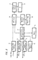
- FIG. 2 An outline of an example of the recording, reproducing method according to the present invention will be described with reference to an optical recording/reproducing device according to the present invention shown in FIG. 2, i.e., a block diagram of signal processing related to a drive device and a flow chart of signal processing in FIG. 3.
- the drive device includes a premastered signal (pit signal) detection unit 11 for detecting a reproducing RF (high-frequency) obtained by reproducing information written as, e.g., pits in the premastered area 5 of the optical recording medium, a maker recording signal detection unit, e.g., a magneto-optical (MO) signal detection unit 12 recorded in the maker recording area 4, a temperature sensor 13, a control circuit and an error detection unit 14, a memory 15, a semiconductor laser (LD) 16, for example, for generating a laser beam for performing recording and reproducing to an optical recording medium, a LD drive circuit 17 for driving the semiconductor laser (LD) 16, an automatic power control circuit (APC) circuit 18 for controlling the LD drive circuit 17 to control the power of laser emission, an emission power monitor 19 for detecting a laser beam from the semiconductor laser (LD) 16 to detect the emission power, a magnetic head 20 serving as a magnetic field application means when magnetic field application is performed in at least one of recording and reproducing to the optical recording medium
- step S21 in FIG. 3 when recording or reproducing of the optical recording medium is started, standard value information detected by the premastered signal (pit signal) detection unit 11 is loaded on the control circuit and the error detection unit 14 (step S21 in FIG. 3), so that error detection is performed (step S22). If it is determined that the value includes an error, the pit signal is loaded again. If it is determined that the value does not include an error, standard value memory writing, i.e., storage is performed to the memory 15 (step S23).
- step S24 the information of the maker recording area 4 from the MO signal detection unit 12 is loaded on the control circuit and the error detection unit 14 (step S24), so that error detection is performed (step S25).
- a correction value obtained from individual information obtained by the MO signal and standard value information obtained by the pit signal are written in the memory 15 (step S26).
- the information stored in the memory 15 is picked out, and signal supply to the automatic power control circuit (APC) circuit 18 of the semiconductor laser (LD) 16 is performed by the control unit 14.
- the signal is compared with a signal from the emission power monitor 19, and the laser drive circuit 17 is controlled to perform emission power control of the laser 16.
- a control signal is supplied to the drive circuit 21 of the magnetic head 20 to perform intensity control of a magnetic field from the magnetic head 20 (step S27).
- step S25 if it is determined that the value includes an error, the MO signal is loaded again (step S28). When the value still has an error after the loading is performed a predetermined number of times (n times), the loading is stopped. The generation of the error and the standard value loaded in advance are written as a correction value in the memory 15 (step S29). On the basis of the correction value, the step S27 described above is performed.
- An ambient temperature is always monitored by the temperature sensor 13.
- recording, reproducing laser powers are controlled such that the laser powers are successively optimum.
- FIG. 4 shows a flow chart of the temperature control.
- a temperature standard (reference) value loaded from the premastered area 5 and a signal detected by the temperature sensor 13 are loaded on the control circuit, error detection unit 14 (step S31). It is checked whether the difference between the detected temperature and the reference value exceeds a certain value or not (step S32). If the difference exceeds the certain value, an amount of correction is calculated from a temperature difference between the detected temperature and the loaded temperature coefficient (step S33), resetting the recording/ reproducing device, i.e., system resetting is performed (step S34).
- step S34 the difference between the detected temperature and the temperature reference is successively monitored to perform the same processes as described above.
- step S32 if the difference between the detected value and the reference value is small, e.g., falls within an allowable range, the temperature monitoring is successively performed without performing resetting or the like.
- a finally manufactured optical recording medium is shifted from a standard value or a center value of a premastered area written in a substrate 1 constituting the optical recording medium when the substrate 1 is molded by a standard margin, the operation conditions of the drive device are corrected in the recording and reproducing, so that optimum recording and reproducing or almost optimum recording and reproducing can be performed.
- the present invention can be applied to not only the disk-type optical recording medium, but also optical recording media having various shapes and forms.
- optical recording medium configuration As described above, according to an optical recording medium configuration according to the present invention and an optical recording and/or optical reproducing method according to the present invention using the optical recording medium configuration, individual drive control information related to the optical recording medium is recorded in the maker recording area. For this reason, a finally manufactured optical recording medium can widens an allowable range of a variation of the premastered area written in a substrate constituting the optical recording medium when the substrate is molded, from a standard value or a center value. Optimum or almost optimum recording and reproducing can be performed to each optical recording medium, and stable recording and reproducing can be performed to each optical recording medium.
- An optical recording medium which is understood to be shifted from a standard margin and which is wasted as a defective optical recording medium can be used as a good product, i.e., merchandise by substantially widening an allowable range so that a rate of good products can be increased. An increase in yield and a reduction in cost can be achieved.
Landscapes
- Physics & Mathematics (AREA)
- Optics & Photonics (AREA)
- Optical Recording Or Reproduction (AREA)
Abstract
Description
| Change in Sensitivity Caused by Repetitive Recording | ||||
| The Number of Times of Recording | 10 | 100 | 1000 | 10000 |
| Reproducing Sensitivity (mW) | 0.00 | 0.00 | +0.02 | +0.05 |
| Recording Sensitivity (mW) | 0.00 | 0.00 | -0.05 | -0.15 |
Claims (16)
- An optical recording medium having a writable recording layer on a substrate and having a maker recording area on the recording layer, wherein
individual drive control information of the optical recording medium is recorded in the maker recording area. - The optical recording medium according to claim 1, wherein
the drive control information is all or part of respective information on recording sensitivity, reproducing sensitivity, temperature dependency of recording sensitivity, temperature dependency of reproducing sensitivity, linear speed dependency of recording sensitivity, linear speed dependency of reproducing sensitivity, recording magnetic field sensitivity, reproducing magnetic field sensitivity, an optimum resolution, optimum asymmetry, a change in sensitivity caused by repetitive recording, and a change in sensitivity caused by repetitive reproducing. - The optical recording medium according to claim 1, wherein the drive control information has a premastered area written by a pattern obtained by molding when the substrate of the optical recording medium is molded.
- The optical recording medium according to claim 1, having plural zones, wherein the same information as all or part of the drive control information is recorded in the maker recording area corresponding to the respective zones.
- An optical recording method for an optical recording medium having a writable recording layer on a substrate and having a maker recording area and a user recording area formed on the recording layer, whereinindividual drive control information of the optical recording medium is recorded in the maker recording area,the optical recording method comprising the steps of controlling a drive circuit based on the drive control information and performing optical recording in the user area by the drive circuit.
- The optical recording method according to claim 5, wherein the drive control information is all or part of respective information on recording sensitivity, reproducing sensitivity, temperature dependency of recording sensitivity, temperature dependency of reproducing sensitivity, linear speed dependency of recording sensitivity, linear speed dependency of reproducing sensitivity, recording magnetic field sensitivity, reproducing magnetic field sensitivity, an optimum resolution, optimum asymmetry, a change in sensitivity caused by repetitive recording, and a change in sensitivity caused by repetitive reproducing.
- The optical recording method according to claim 5, wherein the control step obtains desired control information through cooperation between standard value information of optical recording performed by premastered information written by a pattern obtained by molding when the substrate of the optical recording medium is molded and the drive control information, and controls the drive circuit on the basis of the control information.
- The optical recording method according to claim 5, wherein the same drive control information is written in a plurality of portions of the maker recording area, further comprising a step of judging whether or not information is erroneous based on a required number of the drive control information written in the plurality of portions, and wherein the optical recording step performing an optical recording on the user area of the optical recording medium based on the drive control information from which erroneous information is eliminated based on the judgement.
- An optical reproducing method for an optical recording medium having a writable recording layer on a substrate and having a maker recording area and a user recording area formed on the recording layer, whereinindividual drive control information of the optical recording medium is recorded in the maker recording area,the optical reproducing method comprising the steps of controlling a drive circuit on the basis of the drive control information and performing optical reproducing from the user area by the drive circuit.
- The optical reproducing method according to claim 9, wherein the drive control information is a record of all or part of respective information on recording sensitivity, reproducing sensitivity, temperature dependency of recording sensitivity, temperature dependency of reproducing sensitivity, linear speed dependency of recording sensitivity, linear speed dependency of reproducing sensitivity, recording magnetic field sensitivity, reproducing magnetic field sensitivity, an optimum resolution, optimum asymmetry, a change in sensitivity caused by repetitive recording, and a change in sensitivity caused by repetitive reproducing.
- The optical reproducing method according to claim 9, wherein the control step obtains desired control information through cooperation between standard value information of optical recording performed by premastered information written by a pattern obtained by molding when the substrate of the optical recording medium is molded and the drive control information, and controls the drive circuit on the basis of the control information.
- The optical reproducing method according to claim 9, wherein the same drive control information is written in a plurality of portions of the maker recording area, further comprising a step of judging whether or not information is erroneous based on a required number of the drive control information written in the plurality of portions, and wherein the optical reproducing step performing an optical reproducing from the user area of the optical recording medium based on the drive control information from which erroneous information is eliminated based on the judgement.
- An optical recording/reproducing device for an optical recording medium having, on a substrate, a premastered recording area on which a premastered signal is written by a pattern obtained by molding when the substrate is molded and having a writable recording layer on the substrate, a maker recording area in which a maker recording signal is recorded and a user recording area being formed on the recording layer, whereinindividual drive control information of the optical recording medium is recorded in the maker recording area,the optical recording/reproducing device comprising a laser, an automatic power control circuit of the laser, an emission power monitor for the laser, a premastered signal detection unit for detecting a premastered signal in the premastered area, a maker signal detection unit for detecting a maker recording signal of the maker recording area, anda control circuit which outputs a control signal corrected with respect to a standard value on the basis of the premastered signal and the maker recording signal,the automatic power control circuit automatically controlling the emission power of the laser by the control signal and a monitor signal obtained by the emission power monitor of the laser.
- The optical recording/reproducing device according to claim 13, wherein the drive control information is all or part of respective information on recording sensitivity, reproducing sensitivity, temperature dependency of recording sensitivity, temperature dependency of reproducing sensitivity, linear speed dependency of recording sensitivity, linear speed dependency of reproducing sensitivity, recording magnetic field sensitivity, reproducing magnetic field sensitivity, an optimum resolution, optimum asymmetry, a change in sensitivity caused by repetitive recording, and a change in sensitivity caused by repetitive reproducing.
- The optical recording/reproducing device according to claim 13, further comprising a temperature sensor, wherein the control circuit outputs the control signal corrected based on temperature information from the temperature sensor.
- The optical recording/reproducing device according to claim 13, wherein the same drive control information is written in a plurality of portions of the maker recording area, the control circuit judging whether or not information is erroneous based on a required number of the drive control information written in the plurality of portions as well as performing an optical reproducing from the user area of the optical recording medium based on the drive control information from which erroneous information is eliminated based on the judgement.
Applications Claiming Priority (2)
| Application Number | Priority Date | Filing Date | Title |
|---|---|---|---|
| JP2000098902 | 2000-03-31 | ||
| JP2000098902A JP2001283443A (en) | 2000-03-31 | 2000-03-31 | Optical recording medium, optical recording method, optical reproducing method, and optical recording / reproducing device |
Publications (2)
| Publication Number | Publication Date |
|---|---|
| EP1148479A2 true EP1148479A2 (en) | 2001-10-24 |
| EP1148479A3 EP1148479A3 (en) | 2006-05-10 |
Family
ID=18613327
Family Applications (1)
| Application Number | Title | Priority Date | Filing Date |
|---|---|---|---|
| EP01108178A Ceased EP1148479A3 (en) | 2000-03-31 | 2001-03-30 | Optical recording medium, optical recording method, optical reproducing method, and optical recording/reproducing device |
Country Status (3)
| Country | Link |
|---|---|
| US (1) | US6597647B2 (en) |
| EP (1) | EP1148479A3 (en) |
| JP (1) | JP2001283443A (en) |
Families Citing this family (10)
| Publication number | Priority date | Publication date | Assignee | Title |
|---|---|---|---|---|
| EP1049095A3 (en) * | 1999-04-28 | 2006-06-28 | Victor Company Of Japan, Ltd. | Information recording medium and reproducing apparatus therefor |
| TWI257624B (en) | 2002-02-01 | 2006-07-01 | Matsushita Electric Industrial Co Ltd | Information medium and information recording/reproduction apparatus |
| MXPA04010521A (en) * | 2002-04-24 | 2004-12-13 | Samsung Electronics Co Ltd | Optical information storage medium and method of recording thereon. |
| EP1515315B1 (en) | 2003-08-26 | 2007-07-25 | Ricoh Company, Ltd. | Information recording method, information recording device, optical information recording medium, program for recording information and storage medium |
| EP1667121A4 (en) | 2003-09-19 | 2008-03-19 | Ricoh Kk | Information recorder and information recording system |
| KR20050092165A (en) * | 2004-03-15 | 2005-09-21 | 삼성전자주식회사 | An information storage medium having a plurality of reproduction power information |
| JPWO2007029430A1 (en) * | 2005-09-05 | 2009-03-12 | 日本電気株式会社 | Optical information reproducing method, optical information reproducing apparatus, and optical information recording medium |
| JP2007133920A (en) * | 2005-11-08 | 2007-05-31 | Victor Co Of Japan Ltd | Information reproducing method and information reproducing device |
| JP2008108402A (en) * | 2006-10-27 | 2008-05-08 | Toshiba Corp | Optical disc device and optical disc recording method |
| WO2014041676A1 (en) * | 2012-09-14 | 2014-03-20 | 株式会社日立製作所 | Optical recording device, optical recording method and optical recording medium |
Family Cites Families (4)
| Publication number | Priority date | Publication date | Assignee | Title |
|---|---|---|---|---|
| JP2809835B2 (en) * | 1990-07-30 | 1998-10-15 | 松下電器産業株式会社 | Optical disk device and optical disk |
| JP3111012B2 (en) * | 1996-02-23 | 2000-11-20 | 株式会社リコー | optical disk |
| JP3615021B2 (en) * | 1997-06-30 | 2005-01-26 | 富士通株式会社 | Optical storage device and optical storage medium recording / reproducing method |
| JP3076033B1 (en) * | 1998-09-14 | 2000-08-14 | 松下電器産業株式会社 | Optical information recording / reproducing apparatus and information recording medium |
-
2000
- 2000-03-31 JP JP2000098902A patent/JP2001283443A/en active Pending
-
2001
- 2001-03-30 EP EP01108178A patent/EP1148479A3/en not_active Ceased
- 2001-03-30 US US09/822,068 patent/US6597647B2/en not_active Expired - Fee Related
Also Published As
| Publication number | Publication date |
|---|---|
| JP2001283443A (en) | 2001-10-12 |
| US20020012301A1 (en) | 2002-01-31 |
| US6597647B2 (en) | 2003-07-22 |
| EP1148479A3 (en) | 2006-05-10 |
Similar Documents
| Publication | Publication Date | Title |
|---|---|---|
| US6463020B2 (en) | Arrangements for using detected phase differences for setting laser power levels | |
| US6597647B2 (en) | Optical recording medium having individual drive control information recorded in the maker recording area | |
| EP0944051B1 (en) | Optical storage apparatus and recording and reproducing method of optical storage medium | |
| US7272089B2 (en) | Optical disc recording under adjustable conditions | |
| US6310846B1 (en) | Method for controlling the recording conditions for a second mark using previously determined reproducing conditions for a first mark for optical memory device | |
| JP3780866B2 (en) | Optical disc recording method | |
| CN100380481C (en) | Record carrier and apparatus and method for scanning the record carrier | |
| EP1447797B1 (en) | Optical disk and optical disk apparatus | |
| KR100718621B1 (en) | Optical disk apparatus, focus-value correcting method, and optical disk | |
| US7428198B2 (en) | Optical disc device | |
| US6259669B1 (en) | Technique for reducing cross erasure in an optical disc recording apparatus | |
| JP3860402B2 (en) | Optical disc recording / reproducing apparatus and optical disc recording / reproducing method | |
| US20110305128A1 (en) | Recording device, recording method, and program | |
| US7327651B2 (en) | Optical disc device | |
| US7701828B2 (en) | Optical recording system and method | |
| US20060181987A1 (en) | Method and apparatus for determining the optimal laser power in recordable optical storage systems | |
| JP2005190525A (en) | Information recording method and optical disc apparatus | |
| JPH10255349A (en) | Recording medium recording / reproducing method and recording / reproducing apparatus | |
| KR100318204B1 (en) | Recording Control Method of Optical Disc | |
| US20060007824A1 (en) | Disc reproduction device | |
| JP2002237069A (en) | Optical disk device and track offset correcting method in optical disk device | |
| KR100657727B1 (en) | Tilt control method of optical record player | |
| JP2000020956A (en) | Optical disc device | |
| JP2002008280A (en) | Optical disk device | |
| JPWO2008062536A1 (en) | Information recording apparatus and method, and computer program |
Legal Events
| Date | Code | Title | Description |
|---|---|---|---|
| PUAI | Public reference made under article 153(3) epc to a published international application that has entered the european phase |
Free format text: ORIGINAL CODE: 0009012 |
|
| AK | Designated contracting states |
Kind code of ref document: A2 Designated state(s): AT BE CH CY DE DK ES FI FR GB GR IE IT LI LU MC NL PT SE TR |
|
| AX | Request for extension of the european patent |
Free format text: AL;LT;LV;MK;RO;SI |
|
| PUAL | Search report despatched |
Free format text: ORIGINAL CODE: 0009013 |
|
| AK | Designated contracting states |
Kind code of ref document: A3 Designated state(s): AT BE CH CY DE DK ES FI FR GB GR IE IT LI LU MC NL PT SE TR |
|
| AX | Request for extension of the european patent |
Extension state: AL LT LV MK RO SI |
|
| 17P | Request for examination filed |
Effective date: 20061016 |
|
| 17Q | First examination report despatched |
Effective date: 20061127 |
|
| AKX | Designation fees paid |
Designated state(s): DE FR GB |
|
| STAA | Information on the status of an ep patent application or granted ep patent |
Free format text: STATUS: THE APPLICATION HAS BEEN REFUSED |
|
| 18R | Application refused |
Effective date: 20101220 |