EP1148469A2 - Offline active control of automotive noise - Google Patents
Offline active control of automotive noise Download PDFInfo
- Publication number
- EP1148469A2 EP1148469A2 EP01105548A EP01105548A EP1148469A2 EP 1148469 A2 EP1148469 A2 EP 1148469A2 EP 01105548 A EP01105548 A EP 01105548A EP 01105548 A EP01105548 A EP 01105548A EP 1148469 A2 EP1148469 A2 EP 1148469A2
- Authority
- EP
- European Patent Office
- Prior art keywords
- sensor
- engine
- speaker
- control unit
- cancellation
- Prior art date
- Legal status (The legal status is an assumption and is not a legal conclusion. Google has not performed a legal analysis and makes no representation as to the accuracy of the status listed.)
- Withdrawn
Links
Images
Classifications
-
- G—PHYSICS
- G10—MUSICAL INSTRUMENTS; ACOUSTICS
- G10K—SOUND-PRODUCING DEVICES; METHODS OR DEVICES FOR PROTECTING AGAINST, OR FOR DAMPING, NOISE OR OTHER ACOUSTIC WAVES IN GENERAL; ACOUSTICS NOT OTHERWISE PROVIDED FOR
- G10K11/00—Methods or devices for transmitting, conducting or directing sound in general; Methods or devices for protecting against, or for damping, noise or other acoustic waves in general
- G10K11/16—Methods or devices for protecting against, or for damping, noise or other acoustic waves in general
- G10K11/175—Methods or devices for protecting against, or for damping, noise or other acoustic waves in general using interference effects; Masking sound
- G10K11/178—Methods or devices for protecting against, or for damping, noise or other acoustic waves in general using interference effects; Masking sound by electro-acoustically regenerating the original acoustic waves in anti-phase
- G10K11/1781—Methods or devices for protecting against, or for damping, noise or other acoustic waves in general using interference effects; Masking sound by electro-acoustically regenerating the original acoustic waves in anti-phase characterised by the analysis of input or output signals, e.g. frequency range, modes, transfer functions
- G10K11/17821—Methods or devices for protecting against, or for damping, noise or other acoustic waves in general using interference effects; Masking sound by electro-acoustically regenerating the original acoustic waves in anti-phase characterised by the analysis of input or output signals, e.g. frequency range, modes, transfer functions characterised by the analysis of the input signals only
-
- G—PHYSICS
- G10—MUSICAL INSTRUMENTS; ACOUSTICS
- G10K—SOUND-PRODUCING DEVICES; METHODS OR DEVICES FOR PROTECTING AGAINST, OR FOR DAMPING, NOISE OR OTHER ACOUSTIC WAVES IN GENERAL; ACOUSTICS NOT OTHERWISE PROVIDED FOR
- G10K11/00—Methods or devices for transmitting, conducting or directing sound in general; Methods or devices for protecting against, or for damping, noise or other acoustic waves in general
- G10K11/16—Methods or devices for protecting against, or for damping, noise or other acoustic waves in general
- G10K11/175—Methods or devices for protecting against, or for damping, noise or other acoustic waves in general using interference effects; Masking sound
- G10K11/178—Methods or devices for protecting against, or for damping, noise or other acoustic waves in general using interference effects; Masking sound by electro-acoustically regenerating the original acoustic waves in anti-phase
- G10K11/1785—Methods, e.g. algorithms; Devices
-
- G—PHYSICS
- G10—MUSICAL INSTRUMENTS; ACOUSTICS
- G10K—SOUND-PRODUCING DEVICES; METHODS OR DEVICES FOR PROTECTING AGAINST, OR FOR DAMPING, NOISE OR OTHER ACOUSTIC WAVES IN GENERAL; ACOUSTICS NOT OTHERWISE PROVIDED FOR
- G10K11/00—Methods or devices for transmitting, conducting or directing sound in general; Methods or devices for protecting against, or for damping, noise or other acoustic waves in general
- G10K11/16—Methods or devices for protecting against, or for damping, noise or other acoustic waves in general
- G10K11/175—Methods or devices for protecting against, or for damping, noise or other acoustic waves in general using interference effects; Masking sound
- G10K11/178—Methods or devices for protecting against, or for damping, noise or other acoustic waves in general using interference effects; Masking sound by electro-acoustically regenerating the original acoustic waves in anti-phase
- G10K11/1787—General system configurations
- G10K11/17873—General system configurations using a reference signal without an error signal, e.g. pure feedforward
-
- G—PHYSICS
- G10—MUSICAL INSTRUMENTS; ACOUSTICS
- G10K—SOUND-PRODUCING DEVICES; METHODS OR DEVICES FOR PROTECTING AGAINST, OR FOR DAMPING, NOISE OR OTHER ACOUSTIC WAVES IN GENERAL; ACOUSTICS NOT OTHERWISE PROVIDED FOR
- G10K11/00—Methods or devices for transmitting, conducting or directing sound in general; Methods or devices for protecting against, or for damping, noise or other acoustic waves in general
- G10K11/16—Methods or devices for protecting against, or for damping, noise or other acoustic waves in general
- G10K11/175—Methods or devices for protecting against, or for damping, noise or other acoustic waves in general using interference effects; Masking sound
- G10K11/178—Methods or devices for protecting against, or for damping, noise or other acoustic waves in general using interference effects; Masking sound by electro-acoustically regenerating the original acoustic waves in anti-phase
- G10K11/1787—General system configurations
- G10K11/17879—General system configurations using both a reference signal and an error signal
- G10K11/17883—General system configurations using both a reference signal and an error signal the reference signal being derived from a machine operating condition, e.g. engine RPM or vehicle speed
-
- G—PHYSICS
- G10—MUSICAL INSTRUMENTS; ACOUSTICS
- G10K—SOUND-PRODUCING DEVICES; METHODS OR DEVICES FOR PROTECTING AGAINST, OR FOR DAMPING, NOISE OR OTHER ACOUSTIC WAVES IN GENERAL; ACOUSTICS NOT OTHERWISE PROVIDED FOR
- G10K2210/00—Details of active noise control [ANC] covered by G10K11/178 but not provided for in any of its subgroups
- G10K2210/10—Applications
- G10K2210/128—Vehicles
- G10K2210/1282—Automobiles
- G10K2210/12822—Exhaust pipes or mufflers
-
- G—PHYSICS
- G10—MUSICAL INSTRUMENTS; ACOUSTICS
- G10K—SOUND-PRODUCING DEVICES; METHODS OR DEVICES FOR PROTECTING AGAINST, OR FOR DAMPING, NOISE OR OTHER ACOUSTIC WAVES IN GENERAL; ACOUSTICS NOT OTHERWISE PROVIDED FOR
- G10K2210/00—Details of active noise control [ANC] covered by G10K11/178 but not provided for in any of its subgroups
- G10K2210/30—Means
- G10K2210/301—Computational
- G10K2210/3033—Information contained in memory, e.g. stored signals or transfer functions
-
- G—PHYSICS
- G10—MUSICAL INSTRUMENTS; ACOUSTICS
- G10K—SOUND-PRODUCING DEVICES; METHODS OR DEVICES FOR PROTECTING AGAINST, OR FOR DAMPING, NOISE OR OTHER ACOUSTIC WAVES IN GENERAL; ACOUSTICS NOT OTHERWISE PROVIDED FOR
- G10K2210/00—Details of active noise control [ANC] covered by G10K11/178 but not provided for in any of its subgroups
- G10K2210/30—Means
- G10K2210/321—Physical
- G10K2210/3214—Architectures, e.g. special constructional features or arrangements of features
-
- G—PHYSICS
- G10—MUSICAL INSTRUMENTS; ACOUSTICS
- G10K—SOUND-PRODUCING DEVICES; METHODS OR DEVICES FOR PROTECTING AGAINST, OR FOR DAMPING, NOISE OR OTHER ACOUSTIC WAVES IN GENERAL; ACOUSTICS NOT OTHERWISE PROVIDED FOR
- G10K2210/00—Details of active noise control [ANC] covered by G10K11/178 but not provided for in any of its subgroups
- G10K2210/30—Means
- G10K2210/321—Physical
- G10K2210/3217—Collocated sensor and cancelling actuator, e.g. "virtual earth" designs
-
- G—PHYSICS
- G10—MUSICAL INSTRUMENTS; ACOUSTICS
- G10K—SOUND-PRODUCING DEVICES; METHODS OR DEVICES FOR PROTECTING AGAINST, OR FOR DAMPING, NOISE OR OTHER ACOUSTIC WAVES IN GENERAL; ACOUSTICS NOT OTHERWISE PROVIDED FOR
- G10K2210/00—Details of active noise control [ANC] covered by G10K11/178 but not provided for in any of its subgroups
- G10K2210/30—Means
- G10K2210/321—Physical
- G10K2210/3219—Geometry of the configuration
Definitions
- This invention relates to an active control for automotive induction noise.
- the cancellation signal is generated in real time by a digital signal processor based on detected noise levels.
- a digital signal processor based on detected noise levels.
- Such a system requires a microphone to detect the current engine noise level and a reference signal such as an engine tachometer signal. Based on the signal from the microphone as well as the reference signal, a cancellation signal is created and passed through an audio amplifier to the speaker located in proximity to the air induction system.
- a digital signal processor controller is more expensive than a microprocessor based controller.
- a digital model of the acoustical-mechanical-electrical transmission path of the cancellation signal is required for the stable operation of the digital signal processor based controller. Any change in the physical configuration of the elements included in the signal transmission path will result in the speaker generating loud and annoying noise due to the instabilities arising from the poor modeling of the transmission path.
- the degree of noise cancellation using real time control is limited during engine acceleration since the required cancellation signal must be generated fast enough to track the change in engine noise generated as the engine speed changes.
- real time control requires an error microphone, which must be located such that the ambient vehicle noise does not overwhelm the noise radiating from the annular intake/speaker.
- the active noise attenuation system comprises a speaker, a control unit in communication with the speaker, and a memory unit in communication with the control unit that stores data relating to the cancellation signal.
- the cancellation signal is preferably related to engine data such as a particular engine speed. Generally, there is a proportional relationship between such data and engine noise. Because the cancellation signal is stored in memory, the system need not calculate the cancellation signal in real time.
- the speaker In operation in a vehicle, the speaker is disposed about the air induction system.
- a sensor communicates with the control unit to trigger the recall from memory of the appropriate cancellation signal necessary to attenuate engine noise at the particular engine speed.
- a sensor detects the engine speed and then communicates this speed to the control unit.
- the control unit retrieves from the memory unit the appropriate cancellation waveform and then projects this waveform through the speaker to attenuate engine noise.
- An environmental sensor such as an air temperature, pressure, or humidity sensor, may serve as input to the control unit to affect the particular form of the cancellation signal.
- An important element of this system is the creation and storage of the cancellation signal in the memory unit. While the system normally operates offline, the cancellation signal data for the system is generated in real time. First, engine noise associated with a particular speed is sensed. The cancellation signal needed to attenuate this noise is then determined and then recorded with the particular engine speed. Finally, the cancellation signal data is stored in the memory unit for later recall by the control unit.
- the cancellation signal is not determined in real time but instead recalled from the memory unit by the control unit.
- the response time for such a system is faster than systems currently available.
- a microprocessor rather than a digital signal processor is required for this system.
- a microphone is used to sense and aid in the collection of the cancellation signals, in operation in the vehicle, the system requires no microphone.
- the information may be determined experimentally for a model of a particular vehicle style, and then utilized and programmed into the control for each vehicle made according to that model. Alternatively, the control could be somewhat more complex, and would be stored on the actual individual vehicle.
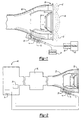
- Figure 1 shows a cross-sectional representation of the invention. Shown are speaker 10, control unit 14, and memory unit 18 within air duct body 22 of an air induction system of a vehicle. As known, the air induction system supplies air to an engine in a manner well-known and not illustrated here. Speaker is an axially symmetric speaker supported to minimize airflow restriction through air induction system.
- Control unit 14 includes a microprocessor and may include analog to digital converter as well as a digital to analog converter. Control unit 14 is in communication with memory unit 18 as well as speaker 10. Amplifier 26 serves to amplify any signal from control unit 14 to speaker 10.
- This cancellation waveform data comprises the data necessary to attenuate noise that is preloaded into memory unit 18. Such data may include the actual attenuating waveforms themselves, scaled versions of these waveforms, or their characteristics all organized in a manner for retrieval by control unit 14.
- the cancellation waveform data comprises at least one cancellation waveform related with engine data such as engine speed.
- sensors 30 and 34 are shown in communication with control unit 14.
- One sensor 30 may detect the engine speed while the other sensor may be a throttle position sensor 34.
- the sensor that detects engine speed 30 provides the timing for the release of the cancellation waveform while the throttle position sensor 34 determines the scaling factor for the amplitude of the cancellation waveform.
- sensors may be environmental sensors that sense air temperature, humidity, and pressure. These environmental conditions, especially air temperature, may impact noise attenuation by the cancellation waveform and may therefore be considered.
- speaker 10 is supported within air duct body 22 at mouth 38 as known in the art.
- engine noise 42 from engine 40 (shown schematically) has traveled from engine 40 though air duct body 22. Since speaker 10 is co-axially mounted and in the same plane as mouth 38, both the radiated engine noise and the cancellation waveform 46 radiating from speaker 10 share a common location thereby minimizing engine noise 42.
- Sensor 30 detects engine speed and communicates with control unit 14.
- the speed of engine 40 may be computed by control unit 14 from sensor 30.
- sensor 30 may emit one pulse every two engine revolutions.
- control unit 14 preferably receives a signal from sensor 30 at about half the engine speed. Of course, other ways of identifying engine speed may be used.
- control unit 14 selects the appropriate cancellation waveform 46 from memory unit 18 and determines the amplification necessary to attenuate engine noise based on the size of the throttle opening according to the throttle position sensor 34.
- Cancellation waveform 46 has a period corresponding to two engine revolutions to match period of engine noise 42
- Sensor 34 determines the size of the throttle opening and communicates the throttle position to control unit 14.
- the amplitude of cancellation waveform 46 is scaled appropriately (a scaling factor of 1 representing a completely open throttle opening while 0 represents a completely closed throttle opening) by control unit 14 through amplifier 26 and then propagated out by speaker 10.
- Cancellation waveform 46 is out of phase with engine noise 42, preferably 180 degrees out of phase.
- a ring buffer may be employed in the control to continue the cancellation waveform 46 until engine speed, throttle position, or any other sensed condition changes in the system. In this way, cancellation waveform will continuously serve to attenuate engine noise until conditions change.
- cancellation waveform 46 it is important to note that the retrieval of cancellation waveform 46 from memory unit 18 take little time to ensure instantaneous response of the system. Even so, the short delay is preferably compensated for the phase of cancellation waveform 46 to accommodate for the delay and ensure optimal wave cancellation.
- the compensation occurs by delaying cancellation waveform a small time T which is slightly longer than the time required by control unit 14 to retrieve and scale cancellation waveform 46.
- the time required by the control unit to retrieve and scale the waveform may be determined experimentally based upon the system and then the time could be programmed into the control.
- cancellation waveforms stored in memory unit 18 are generated and stored using a real time system as shown in Figure 3.
- Speaker 10 is disposed in mouth 38 of air duct body 22 of air induction system with microphone 54 in close proximity.
- amplifier 26 is connected to real-time digital signal processor controller 58 with analog-to-digital inputs 64 and 68 from microphone 54 and engine speed sensor 30, respectively.
- Real-time digital signal processor controller 58 also has digital to analog output 72 to computer 76.
- the embodiment of Figure 3 generates the cancellation waveform data for every engine speed of engine 40 in real time by a real-time digital signal processor controller 58 as already known in the art.
- the cancellation waveform data is collected during a slow acceleration of the engine from idle to redline at wide-open throttle.
- a high-resolution engine speed sensor 30 such as a high-resolution tachometer is employed.
- the signal from sensor 30 is at least 60 pulses per engine revolution.
- the signal from microphone 54 is sampled by the real-time digital signal processor controller 58 through analog-to-digital input 64.
- the real-time cancellation waveform data - the cancellation waveform for each engine speed - is created by this arrangement and communicated to computer 72, which stores this information in memory unit 18 such as an EPROM. Memory unit 18 is subsequently inserted into the system of Figures 1 and 2 to permit reference by control unit 14 of data during vehicle operation.
- the system of Figure 3 also determines the scaling factor used to modify the amplitude of the generated cancellation waveform.
- This scaling factor is determined by operating the real-time digital signal processor controller 58 and configuration of Figure 3 for each degree of throttle opening and determining the cancellation waveform for each degree of opening.
- the degree of change of the amplitude of the cancellation waveform needed to attenuate engine noise over the degrees of throttle opening reflects the scaling factor.
- the scaling factor will vary from engine to engine and vehicle to vehicle.
- the scaling factor is stored in memory unit 18 for use by control unit 14 to determine the amplitude of cancellation waveform depending on the size of the throttle opening.
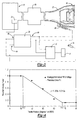
- the scaling factor for a particular engine and vehicle is shown in Figure 4.
- the waveform scaling factor is plotted against throttle position in degrees from wide open (WOT). From 0 degrees to about 16 degrees (open throttle) from throttle wide open, the cancellation waveform need not be scaled down for this particular engine and vehicle. Also, from about 72 to about 90 degrees (closed throttle) from throttle wide open, the cancellation waveform is scaled down significantly. Between about 16 degrees to about 72 degrees, the scaling factor is linear. The scaling factor will vary for each engine and vehicle.
- the system of Figure 3 may be utilized per model type of vehicle to generate information such as that shown in Figure 4 for a particular vehicle style carrying a particular engine. Then, this information can be stored into each vehicle made according to that model. While more complex, the system could be incorporated into each actual vehicle which would generate the information for the particular vehicle. Further, as mentioned above, sensors sensing environmental factors may also be incorporated into the information such as shown in Figure 4. Again, while this information would be more complex to generate, store and utilize, it would also provide more effective cancellation of noise.
- the information tied to particular environmental conditions can be gathered in a similar fashion to that explained above with regard to Figure 3. Varying environmental conditions can be changed under a control setting, and the resulting information stored. Further, the structure and processes for positioning mounting and operating this speaker may be as known. This invention relates to the generation of a preferred waveform for cancellation of condition.
Landscapes
- Physics & Mathematics (AREA)
- Engineering & Computer Science (AREA)
- Acoustics & Sound (AREA)
- Multimedia (AREA)
- Soundproofing, Sound Blocking, And Sound Damping (AREA)
- Fittings On The Vehicle Exterior For Carrying Loads, And Devices For Holding Or Mounting Articles (AREA)
- Noise Elimination (AREA)
Abstract
Description
Claims (20)
- A noise attenuation system comprising:a speaker;a control unit in communication with said speaker; anda memory unit in communication with said control unit storing cancellation waveform data related to a system condition.
- The active noise attenuation system of claim 1 wherein said system condition is engine data.
- The active noise attenuation system of claim 2 wherein said engine data is engine speed.
- The active noise attenuation system of claim 1 further including at least one sensor in communication with said control unit.
- The active noise attenuation system of claim 4 wherein said sensor is a tachometer.
- The active noise attenuation system of claim 4 wherein said sensor is a throttle position sensor.
- The active noise attenuation system of claim 4 wherein said sensor is an environmental sensor.
- The active noise attenuation system of claim 1 wherein said speaker is disposed as part of an air induction system.
- An air induction system comprising:an air duct body having a speaker;a control unit in communication with said speaker;a memory unit in communication with said control unit storing cancellation waveform data wherein said cancellation waveform data comprises at least one cancellation waveform related with engine data.
- The active noise attenuation system of claim 9 wherein said engine data relates to engine speed.
- The active noise attenuation system of claim 9 further including at least one sensor in communication with said control unit.
- The active noise attenuation system of claim 11 wherein said sensor is a tachometer.
- The active noise attenuation system of claim 11 wherein said sensor is a throttle position sensor.
- The active noise attenuation system of claim 11 wherein said sensor is an environmental sensor.
- The active noise attenuation system of claim 11 wherein said speaker is disposed about an air induction system.
- A method of attenuating noise comprising the steps of:storing in memory at least one cancellation waveform;retrieving the cancellation waveform needed to attenuate a noise based upon a sensed engine condition; andattenuating the noise using the cancellation waveform.
- The method of claim 16 wherein the noise relates to engine noise.
- The method of claim 16 wherein the at least one cancellation waveform is related with engine speed and is retrieved and used to attenuate the noise.
- The method of claim 16 wherein the noise is attenuated about air induction system.
- The method of claim 16 further comprising the step of scaling the cancellation waveform.
Applications Claiming Priority (2)
| Application Number | Priority Date | Filing Date | Title |
|---|---|---|---|
| US19807700P | 2000-04-17 | 2000-04-17 | |
| US198077P | 2000-04-17 |
Publications (2)
| Publication Number | Publication Date |
|---|---|
| EP1148469A2 true EP1148469A2 (en) | 2001-10-24 |
| EP1148469A3 EP1148469A3 (en) | 2003-06-18 |
Family
ID=22731899
Family Applications (1)
| Application Number | Title | Priority Date | Filing Date |
|---|---|---|---|
| EP01105548A Withdrawn EP1148469A3 (en) | 2000-04-17 | 2001-03-06 | Offline active control of automotive noise |
Country Status (2)
| Country | Link |
|---|---|
| US (1) | US20010046300A1 (en) |
| EP (1) | EP1148469A3 (en) |
Cited By (1)
| Publication number | Priority date | Publication date | Assignee | Title |
|---|---|---|---|---|
| GB2378081A (en) * | 2001-06-21 | 2003-01-29 | Ray Hudson Ltd | Active noise cancellation using recorded sounds |
Families Citing this family (11)
| Publication number | Priority date | Publication date | Assignee | Title |
|---|---|---|---|---|
| EP1143411A3 (en) * | 2000-04-06 | 2004-11-03 | Siemens VDO Automotive Inc. | Active noise cancellation stability solution |
| US7139401B2 (en) * | 2002-01-03 | 2006-11-21 | Hitachi Global Storage Technologies B.V. | Hard disk drive with self-contained active acoustic noise reduction |
| US6825786B1 (en) * | 2003-05-06 | 2004-11-30 | Standard Microsystems Corporation | Associative noise attenuation |
| US20040240675A1 (en) * | 2003-05-29 | 2004-12-02 | International Business Machines Corporation | Autonomic manipulation of noise sources within computers |
| US20040243405A1 (en) * | 2003-05-29 | 2004-12-02 | International Business Machines Corporation | Service method for providing autonomic manipulation of noise sources within computers |
| US8300842B2 (en) * | 2004-05-21 | 2012-10-30 | Mahle International Gmbh | Robust system for sound enhancement from a single engine sensor |
| DE102005011747B3 (en) * | 2005-03-11 | 2006-06-29 | Benteler Automobiltechnik Gmbh | Active exhaust gas silencer for motor vehicle has membrane set in flexural oscillations by excitation by converter so that on surface facing exhaust gas flow structure-borne noise tuned to exhaust gas noise is created |
| US20090058633A1 (en) * | 2007-08-31 | 2009-03-05 | Matsushita Electric Industrial Co., Ltd. | Anc notch filter adaptation system and method for handling road noise peak shifts in a motor vehicle |
| DE102011084567C5 (en) * | 2011-10-14 | 2019-08-14 | Eberspächer Exhaust Technology GmbH & Co. KG | Active muffler |
| DE102012201725B4 (en) * | 2012-02-06 | 2016-02-25 | Eberspächer Exhaust Technology GmbH & Co. KG | Active muffler |
| DE102016120038A1 (en) * | 2016-10-20 | 2018-04-26 | Ask Industries Gmbh | Method and device for suppressing acoustic interference signals resulting from the operation of a motor vehicle-side drive unit |
Family Cites Families (47)
| Publication number | Priority date | Publication date | Assignee | Title |
|---|---|---|---|---|
| US3936606A (en) * | 1971-12-07 | 1976-02-03 | Wanke Ronald L | Acoustic abatement method and apparatus |
| GB2076049B (en) * | 1980-05-17 | 1983-10-26 | Rolls Royce | Variable acoustic impedance lining |
| FR2501532B1 (en) * | 1981-03-13 | 1985-12-13 | Rhone Poulenc Spec Chim | CATALYST AND METHOD FOR THE TREATMENT OF INDUSTRIAL WASTE GASES CONTAINING SULFUR COMPOUNDS |
| US4665549A (en) * | 1985-12-18 | 1987-05-12 | Nelson Industries Inc. | Hybrid active silencer |
| GB8603678D0 (en) * | 1986-02-14 | 1986-03-19 | Gen Electric Co Plc | Active noise control |
| US5446790A (en) * | 1989-11-24 | 1995-08-29 | Nippondenso Co., Ltd. | Intake sound control apparatus |
| US5457749A (en) * | 1990-04-09 | 1995-10-10 | Noise Cancellation Technologies, Inc. | Electronic muffler |
| US5229556A (en) * | 1990-04-25 | 1993-07-20 | Ford Motor Company | Internal ported band pass enclosure for sound cancellation |
| US5319165A (en) * | 1990-04-25 | 1994-06-07 | Ford Motor Company | Dual bandpass secondary source |
| US5692052A (en) * | 1991-06-17 | 1997-11-25 | Nippondenso Co., Ltd. | Engine noise control apparatus |
| JP3094517B2 (en) * | 1991-06-28 | 2000-10-03 | 日産自動車株式会社 | Active noise control device |
| US5170019A (en) * | 1991-07-25 | 1992-12-08 | Lee Jung W | Sound muffling device for internal combustion engines |
| US5550334A (en) * | 1991-10-30 | 1996-08-27 | Noise Cancellation Technologies, Inc. | Actively sound reduced muffler having a venturi effect configuration |
| US5336856A (en) * | 1992-07-07 | 1994-08-09 | Arvin Industries, Inc. | Electronic muffler assembly with exhaust bypass |
| JP3016972B2 (en) * | 1992-09-03 | 2000-03-06 | パロマ工業株式会社 | Pulse combustor |
| JPH06149268A (en) * | 1992-11-02 | 1994-05-27 | Fuji Heavy Ind Ltd | In-cabin noise reducing device |
| US5386477A (en) * | 1993-02-11 | 1995-01-31 | Digisonix, Inc. | Active acoustic control system matching model reference |
| JP3410141B2 (en) * | 1993-03-29 | 2003-05-26 | 富士重工業株式会社 | Vehicle interior noise reduction device |
| US5587563A (en) * | 1993-06-04 | 1996-12-24 | Dipti Kr. Datta | Air handling structure for pan inlet and outlet |
| US5420932A (en) * | 1993-08-23 | 1995-05-30 | Digisonix, Inc. | Active acoustic attenuation system that decouples wave modes propagating in a waveguide |
| US5418873A (en) * | 1993-09-09 | 1995-05-23 | Digisonix, Inc. | Active acoustic attenuation system with indirect error sensing |
| DE4342133A1 (en) * | 1993-12-10 | 1995-06-14 | Nokia Deutschland Gmbh | Arrangement for active noise reduction |
| JP3099217B2 (en) * | 1994-04-28 | 2000-10-16 | 株式会社ユニシアジェックス | Active noise control system for automobiles |
| US5513266A (en) * | 1994-04-29 | 1996-04-30 | Digisonix, Inc. | Integral active and passive silencer |
| CA2148962C (en) * | 1994-05-23 | 2000-03-28 | Douglas G. Pedersen | Coherence optimized active adaptive control system |
| US5586190A (en) * | 1994-06-23 | 1996-12-17 | Digisonix, Inc. | Active adaptive control system with weight update selective leakage |
| US5557682A (en) * | 1994-07-12 | 1996-09-17 | Digisonix | Multi-filter-set active adaptive control system |
| US5590205A (en) * | 1994-08-25 | 1996-12-31 | Digisonix, Inc. | Adaptive control system with a corrected-phase filtered error update |
| US5621803A (en) * | 1994-09-02 | 1997-04-15 | Digisonix, Inc. | Active attenuation system with on-line modeling of feedback path |
| US5541373A (en) * | 1994-09-06 | 1996-07-30 | Digisonix, Inc. | Active exhaust silencer |
| US5627747A (en) * | 1994-10-13 | 1997-05-06 | Digisonix, Inc. | System for developing and operating an active sound and vibration control system |
| US5570425A (en) * | 1994-11-07 | 1996-10-29 | Digisonix, Inc. | Transducer daisy chain |
| US5561598A (en) * | 1994-11-16 | 1996-10-01 | Digisonix, Inc. | Adaptive control system with selectively constrained ouput and adaptation |
| JPH08158966A (en) * | 1994-11-30 | 1996-06-18 | Nippondenso Co Ltd | Noise control device of internal combustion engine |
| US5602928A (en) * | 1995-01-05 | 1997-02-11 | Digisonix, Inc. | Multi-channel communication system |
| US5633795A (en) * | 1995-01-06 | 1997-05-27 | Digisonix, Inc. | Adaptive tonal control system with constrained output and adaptation |
| US5602929A (en) * | 1995-01-30 | 1997-02-11 | Digisonix, Inc. | Fast adapting control system and method |
| US5677960A (en) * | 1995-05-11 | 1997-10-14 | Victor Company Of Japan, Ltd. | On-vehicle sound control apparatus |
| US5715320A (en) * | 1995-08-21 | 1998-02-03 | Digisonix, Inc. | Active adaptive selective control system |
| DE19531402C2 (en) * | 1995-08-26 | 1999-04-01 | Mannesmann Sachs Ag | Device and method for influencing vibrations in a passenger compartment of a motor vehicle and device and method for detecting defects in a motor vehicle |
| US5710822A (en) * | 1995-11-07 | 1998-01-20 | Digisonix, Inc. | Frequency selective active adaptive control system |
| US5828759A (en) * | 1995-11-30 | 1998-10-27 | Siemens Electric Limited | System and method for reducing engine noise |
| US5706344A (en) * | 1996-03-29 | 1998-01-06 | Digisonix, Inc. | Acoustic echo cancellation in an integrated audio and telecommunication system |
| US5701350A (en) * | 1996-06-03 | 1997-12-23 | Digisonix, Inc. | Active acoustic control in remote regions |
| US5963651A (en) * | 1997-01-16 | 1999-10-05 | Digisonix, Inc. | Adaptive acoustic attenuation system having distributed processing and shared state nodal architecture |
| US6084971A (en) * | 1997-06-10 | 2000-07-04 | Siemens Electric Limited | Active noise attenuation system |
| US6094601A (en) * | 1997-10-01 | 2000-07-25 | Digisonix, Inc. | Adaptive control system with efficiently constrained adaptation |
-
2001
- 2001-02-08 US US09/779,725 patent/US20010046300A1/en not_active Abandoned
- 2001-03-06 EP EP01105548A patent/EP1148469A3/en not_active Withdrawn
Cited By (1)
| Publication number | Priority date | Publication date | Assignee | Title |
|---|---|---|---|---|
| GB2378081A (en) * | 2001-06-21 | 2003-01-29 | Ray Hudson Ltd | Active noise cancellation using recorded sounds |
Also Published As
| Publication number | Publication date |
|---|---|
| US20010046300A1 (en) | 2001-11-29 |
| EP1148469A3 (en) | 2003-06-18 |
Similar Documents
| Publication | Publication Date | Title |
|---|---|---|
| EP1148469A2 (en) | Offline active control of automotive noise | |
| KR101876022B1 (en) | An apparatus for controlling engine noise to reflect engine vibration and driving condition | |
| US7106866B2 (en) | Active noise cancellation stability solution | |
| JP3099217B2 (en) | Active noise control system for automobiles | |
| US6845162B1 (en) | Device for active sound control in a space | |
| US5319715A (en) | Noise sound controller | |
| US20040086135A1 (en) | Active noise control system using pure feedforward method with order-based offline calibration | |
| EP1193683A2 (en) | Driving mode for active noise cancellation | |
| EP2110523A1 (en) | A device and method for active noise cancellation in an exhaust gas channel of a combustion engine | |
| JP2001317420A (en) | Conduit system having electromechanical transducer for generating corrective noise | |
| US20030112981A1 (en) | Active noise control with on-line-filtered C modeling | |
| JP2980007B2 (en) | Exhaust sound quality improvement device | |
| JP3008328B2 (en) | Active noise control system for automobiles | |
| JP2008013064A (en) | Driving sound transmission device for internal combustion engine for automobile | |
| JP3540334B2 (en) | Silencers in passenger compartments and cabin | |
| US6917687B2 (en) | Active noise control using a single sensor input | |
| JP3077331B2 (en) | Active noise reduction device | |
| US20040195040A1 (en) | Powerful sound for powerful engines | |
| EP1162599A2 (en) | Recalibration of active noise cancellation system | |
| JPH05257482A (en) | Silencer for intake duct | |
| JP3332162B2 (en) | Active silencer | |
| JP2573235B2 (en) | Air intake and exhaust system silencer for automobiles, etc. | |
| JPH0586833A (en) | Active noise reduction device | |
| JPH0719135A (en) | Noise control device | |
| US20040156511A1 (en) | Intake sound control unsing pure feedforward method with order-based offline calibration |
Legal Events
| Date | Code | Title | Description |
|---|---|---|---|
| PUAI | Public reference made under article 153(3) epc to a published international application that has entered the european phase |
Free format text: ORIGINAL CODE: 0009012 |
|
| AK | Designated contracting states |
Kind code of ref document: A2 Designated state(s): AT BE CH CY DE DK ES FI FR GB GR IE IT LI LU MC NL PT SE TR |
|
| AX | Request for extension of the european patent |
Free format text: AL;LT;LV;MK;RO;SI |
|
| PUAL | Search report despatched |
Free format text: ORIGINAL CODE: 0009013 |
|
| AK | Designated contracting states |
Designated state(s): AT BE CH CY DE DK ES FI FR GB GR IE IT LI LU MC NL PT SE TR |
|
| AX | Request for extension of the european patent |
Extension state: AL LT LV MK RO SI |
|
| RAP1 | Party data changed (applicant data changed or rights of an application transferred) |
Owner name: 3840620 CANADA INC. |
|
| RAP1 | Party data changed (applicant data changed or rights of an application transferred) |
Owner name: SIEMENS VDO AUTOMOTIVE INC. |
|
| AKX | Designation fees paid |
Designated state(s): DE FR GB |
|
| STAA | Information on the status of an ep patent application or granted ep patent |
Free format text: STATUS: THE APPLICATION IS DEEMED TO BE WITHDRAWN |
|
| 18D | Application deemed to be withdrawn |
Effective date: 20031219 |