EP1148419A1 - Debugging embedded systems - Google Patents
Debugging embedded systems Download PDFInfo
- Publication number
- EP1148419A1 EP1148419A1 EP01300901A EP01300901A EP1148419A1 EP 1148419 A1 EP1148419 A1 EP 1148419A1 EP 01300901 A EP01300901 A EP 01300901A EP 01300901 A EP01300901 A EP 01300901A EP 1148419 A1 EP1148419 A1 EP 1148419A1
- Authority
- EP
- European Patent Office
- Prior art keywords
- application
- target
- file
- memory
- subroutine
- Prior art date
- Legal status (The legal status is an assumption and is not a legal conclusion. Google has not performed a legal analysis and makes no representation as to the accuracy of the status listed.)
- Withdrawn
Links
Images


Classifications
-
- G—PHYSICS
- G06—COMPUTING OR CALCULATING; COUNTING
- G06F—ELECTRIC DIGITAL DATA PROCESSING
- G06F11/00—Error detection; Error correction; Monitoring
- G06F11/36—Prevention of errors by analysis, debugging or testing of software
- G06F11/362—Debugging of software
- G06F11/3648—Debugging of software using additional hardware
- G06F11/3656—Debugging of software using additional hardware using a specific debug interface
Definitions
- the present invention relates to a method and apparatus for operating a target computer system in the presence of a host computer and more particularly but not exclusively between a host computer and an embedded target computer system.
- an engineer can debug the embedded system.
- Debugging software on the host computer provides access by the engineer into the embedded system.
- the engineer uses the host computer and debugging software to set break points which stop threads of execution on the target embedded system, monitor registers in the target, monitor memory states and monitor input and output data.
- the engineer may also restart threads which have been previously stopped and perform a variety of other tasks including rebooting the target computer using the host.
- the term 'digital signal processor' includes microprocessors in general and other like digitally operating processing devices.
- a method of operating a target computer system wherein said target computer system has a memory comprising plural addressable locations and is adapted to run an application, the method comprising providing on a host computer a file, comprising a subroutine required for operation of said application; dynamically loading said file from said host computer to said memory of said target computer system, whereby said file has an entry point at a dynamically-determined addressable location; storing at a predetermined one of said addressable locations data representative of the address of said entry point; running said application, whereby said application determines said data representative of said address thereby accessing said subroutine; and running said subroutine.
- a device for operating an embedded digital signal processor said embedded signal processor having a memory comprising plural addressable locations, and being adapted to run an application
- the device comprising a host computer connected to said embedded digital signal processor, said host computer comprising a computer file including a subroutine required for said application; said host computer comprising a linker-loader connected to said link and operative to send said file and dynamically load said file to said memory of said embedded computer system whereby said file has an entry point at one of said addressable locations, said linker-loader comprising means for storing at a predetermined one of said addressable locations data representative of the address of said entry point; said embedded digital signal processor comprising processor circuitry running said application whereby said application determines said data representative of said address, thereby accessing said file to enable said application to run.
- said predetermined one of said addressable locations is a predetermined address in the stack of an exception handler.
- a host computer 1 includes an input device such as a keyboard 2 and runs debugging software 4 for a target embedded system 100, the host and target being connected via a communications link 101, 102.
- This link is shown figuratively in Figure 1 as two separate paths with a first path 101 conveying data from the host machine 1 to the target machine 100 and a second path 102 connecting to the target computer 100 to the host computer 1. It will be understood that the link may be of any conventional type that allows two-way communication. Such communication need not be simultaneous.
- the target system typically includes a microprocessor or other processing circuitry, hereinafter referred to as a digital signal processor.
- the host computer further includes a file 3, hereinafter referred to as a library, containing a collection of subroutines and information that will be used by the target computer to implement a multi-layered communication protocol over the physical link 101, 102.
- a file 3 hereinafter referred to as a library, containing a collection of subroutines and information that will be used by the target computer to implement a multi-layered communication protocol over the physical link 101, 102.
- the link 101 outgoing from the host computer 1 to the target computer 100 is shown figuratively as connected to four portions of the target system, namely a first application 121, a second application 122, a block 123 whereby the embedded digital signal processor of the target system 100 may be reset, and to the volatile memory 200 of the target system.
- the debugging software 4 may communicate over the link 101 to interrogate or monitor the registers in the target, the memory in the target, to stop and restart threads of execution.
- the applications 121, 122 may be stored in read only memory or may be downloaded via a separate link (not shown) at run-time, eg into RAM 200.
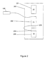
- the target system 100 includes an exception handler 20 loaded into a memory area 201, the exception handler 20 having a stack 21 in a reserved area of memory 202 the stack including a reserved location 205.
- the reserved location 205 is selected as the bottom of the stack.
- the host system 1 may dynamically load the exception handler stack into the target memory.
- the target includes a hard-wired location 190 accessible to both the target and the host, hereinafter referred to as a vector.
- a vector is a reserved area, typically at a hard-wired location, used to contain address data of a key system entity.
- a pointer is a general holder of the address of a selected (arbitrary) entity.
- the library 3 is accessed by the linker-loader 120 of the host which dynamically loads the library to a suitable vacant area of memory 203 of the target according to the usage of memory by applications, data and functions, to provide a loaded library 30 having an entry point 204 within the region of memory 203.
- the linker-loader 120 determines where in the memory of the target to load the stack.
- the linker-loader stores at the bottom stack location 205, hereinafter referred to as the entry point pointer, information representing the entry point 204 and loads the location of the stack into the vector 190.
- the information stored by the vector 190 may be of various forms, including the absolute address of the exception handler stack 202 or other information such as an offset.
- entry point pointer 205 is set to contain a predetermined value indicative of the fact that no library is available, as will be described below.
- This predetermined value may be a value that is not a valid address.
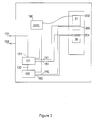
- the first application 121 may be initiated by the host computer 1 at an input 131. If the first application 121 needs to input data from the host computer 1 then it must make use of the dynamic library 30. To do this, application 121 reads the vector 190 and from its contents accesses the address of the exception handler stack 202, offsets to the entry point pointer 205 which results in the entry point into the dynamic link library 30 being supplied to the application at input 141. The application fetches information from the dynamic link library 30 at terminal 151. The application 121 is thus able, by use of the required subroutines in the library 30 to "translate" information coming in over link 101 from the host computer.
- Figure 3 shows that the first application 121 is capable of starting the second application 122 over a path 132. If during execution of the second application 122 there is a requirement for the second application to input or output data from or to the host computer 1, the second application uses the vector 190 to load the entry point data from memory location 205 over the path 142 and accesses the library 30 over the path 152. This in turn enables the second application 122 to input or output data as required.
- Each of the applications typically comprises a start up code.
- the system described uses a single region of memory 202 for the exception handler stack 21. However, where more than one application exists in the embedded system, each may use a different region of memory for the stack of its exception handler. If this occurs, then when a host is connected, a region of memory known to the host must be reserved for this stack and the vector of the target updated to point to this region. The consequence is that all applications use a single area of stack for the particular exception. This ensures that the host has a single stack area, which it will use for the linker-loader 120 to store the address information of the library 30.
- each of the stack regions will be valid for a particular time period and the host will be unable to determine which of these stack regions to write the relevant data to at any one time.
- an application may start. In the first, the host starts the application, in the second the application is started by the target following reset, eg power-up, and in the third, the application is started by another application, referred to here as the initiating application.
- the application should run correctly without recourse to the library, and if the application tries to call the library, an error should be indicated.
- the provision of the dynamic link library depends on how the initiating application was started. If the initiating application was started by the host, then the dynamic link library should be made available: if the initiating application started after target reset, then no library should be needed. (It will of course be understood by those skilled in the art that a whole chain of applications may exist, in which case the decision depends on how the first in the chain started up) To cope with the above situation, the embodiment initialises the contents of the entry point pointer 205 according to the following rules: -
- the application start up code assumes that the entry point pointer value is valid - i.e. the host has set the value stored by the entry point pointer 205 to point to a dynamic library, which the host has downloaded to the target.
- the application start up code will place the above-discussed "no library available" value in entry point pointer 205 indicating that there is no available dynamic library.
- the target digital signal processor supports a mechanism whereby the host can set a single bit of state in a register of the target, which is initialised upon an input to reset logic 123, i.e., a processor reset.
- This bit is hereinafter referred to as the "host-connected bit” and typically resides in a processor register or a memory-mapped register.
- the host-connected bit is initialised by the digital signal processor reset-logic.
- the start up code of the first application to be executed reads the host-connected bit, and because it is initialised determines that the host is regarded as not connected. The code then sets the contents of memory location 205 to the no-library value.
- the library may be dynamically loaded, whereby the host determines its entry point, and then the stack - containing the entry point pointer set to the entry point - may be dynamically loaded.
- the start up code of the first application then executes, reads the host-connected bit (which has been inverted) and decides that a host is connected. As a result, it is assumed that the host has loaded a library, and correctly set the entry point pointer. Thus the entry point pointer 205 is left unchanged.
- the dynamically loaded subroutine is called with two machine-word sized parameters. It returns a machine-word sized value.
- the first parameter is a value that represents an operation to perform, the second a parameter for that operation. Certain operations do not use the second parameter. Similarly, it is not necessary for an operation to utilise the return value.
- the application will have been provided at the time of writing, with the values representing the operations anticipated as necessary. These values are then used in calling the relevant subroutine from the library.
- the library may include a routine translating the values from the application into different values corresponding to those needed by the library.
- One such operation will determine whether the host is connected. This operation will be used by the application by calling the input/output library subroutine with the first parameter containing a reserved value, which represents 'host connected operation'. The second parameter is not used by this operation so an arbitrary value may be passed. The subroutine will determine whether the host is connected with an internal action and return one of two possible values, which are 'host-connected' and 'host not connected'.
- the two-parameter model provides very good backward compatibility to legacy applications, which cannot be changed.
- a later dynamic library may provide additional features. Each additional feature may be accessed by using a value of the first parameter that was not available in earlier libraries. Features that were present in older libraries are provided in the newer libraries and each of these will be accessed with the same value for the first parameter in both old and new libraries.
- the second parameter remains a 'feature-specific' parameter.
- a routine may be written that contains a feature that may be called by the application when appropriate to prevent the bug from occurring, or to mask the bug.
- This routine may be incorporated within a library on the host, and loaded dynamically into the target at the start of a debug session. Components that do not possess the bug will not require the routine and may be provided with a version of the library that does not have the bug work-round feature. Such a version provides a subset of library functionality such as input/output capability.
- a processor register 1190 which is large enough to contain a pointer, is reserved for use by the input/output system.
- the digital signal processor vector to an exception handler stack and the pointer at a reserved position of the exception handler stack are not necessary.
- the register is initialised by the application start-up code to contain the "no library available" value if the host is not connected. If the host is connected, the host places a value in this register pointing to the entry point 1204 of IO dynamic library 1300, which the host has loaded onto the target.
- the application When the application wishes to perform input/output, it looks at the value in the reserved register 1190. If this value is not the special 'no library available' value, it is assumed to be the address of the entry point 1204 to the input/output subroutine. The application calls the subroutine at this address to carry out input/output.
Landscapes
- Engineering & Computer Science (AREA)
- Computer Hardware Design (AREA)
- Theoretical Computer Science (AREA)
- Quality & Reliability (AREA)
- Physics & Mathematics (AREA)
- General Engineering & Computer Science (AREA)
- General Physics & Mathematics (AREA)
- Debugging And Monitoring (AREA)
Abstract
Description
Claims (9)
- A method of operating a target computer system, wherein said target computer system has a memory comprising plural addressable locations and is adapted to run an application, the method comprising:-providing on a host computer a file, comprising a subroutine required for operation of said application;dynamically loading said file from said host computer to said memory of said target computer system, whereby said file has an entry point at a dynamically-determined addressable location;storing at a predetermined one of said addressable locations data representative of the address of said entry point;running said application, whereby said application determines said data representative of said address thereby accessing said subroutine; andrunning said subroutine.
- A method of debugging a target system connected to a host computer, the target having a digital signal processor with a memory including a reserved storage location designated as a vector, said memory further storing an application program, the method comprising:loading a stack into said memory;storing in said reserved location information indicative of said stack location;;dynamically loading a computer file into said memory, said file containing a subroutine required for use by said application program; andstoring at a predetermined location in said stack data indicative of an entry point into said dynamically loaded file;running said application on said target, whereby said application accesses said vector to thereby call said entry point and thus run said subroutine.
- A method as claimed in claim 2 wherein the subroutine allows transfer of data to or from the host computer.
- A method as claimed in claim 2 wherein the subroutine allows said application to work round a hardware error in said target.
- A device for operating an embedded digital signal processor, said embedded signal processor having a memory comprising plural addressable locations, and being adapted to run an application,the device comprising a host computer connected to said embedded digital signal processor, said host computer comprising a computer file including a subroutine required for said application;said host computer comprising a linker-loader connected to said link and operative to send said file and dynamically load said file to said memory of said embedded computer system whereby said file has an entry point at one of said addressable locations, said linker-loader comprising means for storing at a predetermined one of said addressable locations data representative of the address of said entry point;said embedded digital signal processor comprising processor circuitry running said application whereby said application determines said data representative of said address, thereby accessing said file to enable said application to run.
- The method of claim 2 or the device of claim 5 wherein said predetermined one of said addressable locations is a predetermined address in the stack of an exception handler.
- A debugging device comprising a target system connected to a host computer, the target having a digital signal processor with a memory including a reserved storage location designated as a vector, said memory further storing an application program, the device comprising:first loading circuitry for loading a stack into said memory;vector writing circuitry for storing in said reserved location information indicative of said stack location;dynamic loading circuitry in said host for loading a computer file into said memory of said digital signal processor, said file containing a subroutine required for use by said application program;stack writing circuitry for storing at a predetermined location in said stack data indicative of an entry point into said dynamically loaded file;wherein when said digital signal processor runs said application, said application accesses said vector to thereby call said entry point and thus runs said subroutine.
- The device of claim 7 wherein the subroutine allows transfer of data to or from the host computer.
- The device of claim 7 wherein the subroutine allows said application to work round a hardware error in said target.
Applications Claiming Priority (2)
| Application Number | Priority Date | Filing Date | Title |
|---|---|---|---|
| GB0009940 | 2000-04-20 | ||
| GB0009940A GB0009940D0 (en) | 2000-04-20 | 2000-04-20 | Debugging embedded system |
Publications (1)
| Publication Number | Publication Date |
|---|---|
| EP1148419A1 true EP1148419A1 (en) | 2001-10-24 |
Family
ID=9890395
Family Applications (1)
| Application Number | Title | Priority Date | Filing Date |
|---|---|---|---|
| EP01300901A Withdrawn EP1148419A1 (en) | 2000-04-20 | 2001-02-01 | Debugging embedded systems |
Country Status (2)
| Country | Link |
|---|---|
| EP (1) | EP1148419A1 (en) |
| GB (1) | GB0009940D0 (en) |
Cited By (1)
| Publication number | Priority date | Publication date | Assignee | Title |
|---|---|---|---|---|
| US10585454B2 (en) | 2016-07-22 | 2020-03-10 | Hewlett-Packard Development Company, L.P. | Outer cases for computing devices |
Citations (2)
| Publication number | Priority date | Publication date | Assignee | Title |
|---|---|---|---|---|
| US5394544A (en) * | 1989-08-07 | 1995-02-28 | Ricoh Co., Ltd. | Software system debugger with distinct interrupt vector maps for debugging and application programs |
| US5901225A (en) * | 1996-12-05 | 1999-05-04 | Advanced Micro Devices, Inc. | System and method for performing software patches in embedded systems |
-
2000
- 2000-04-20 GB GB0009940A patent/GB0009940D0/en not_active Ceased
-
2001
- 2001-02-01 EP EP01300901A patent/EP1148419A1/en not_active Withdrawn
Patent Citations (2)
| Publication number | Priority date | Publication date | Assignee | Title |
|---|---|---|---|---|
| US5394544A (en) * | 1989-08-07 | 1995-02-28 | Ricoh Co., Ltd. | Software system debugger with distinct interrupt vector maps for debugging and application programs |
| US5901225A (en) * | 1996-12-05 | 1999-05-04 | Advanced Micro Devices, Inc. | System and method for performing software patches in embedded systems |
Cited By (1)
| Publication number | Priority date | Publication date | Assignee | Title |
|---|---|---|---|---|
| US10585454B2 (en) | 2016-07-22 | 2020-03-10 | Hewlett-Packard Development Company, L.P. | Outer cases for computing devices |
Also Published As
| Publication number | Publication date |
|---|---|
| GB0009940D0 (en) | 2000-06-07 |
Similar Documents
| Publication | Publication Date | Title |
|---|---|---|
| US6529985B1 (en) | Selective interception of system calls | |
| EP1224543B1 (en) | Fixing applications that are incompatible to the operating system by providing stubs for apis | |
| US6959441B2 (en) | Intercepting system API calls | |
| KR100306456B1 (en) | Method for rebooting an operating system | |
| US6219828B1 (en) | Method for using two copies of open firmware for self debug capability | |
| US20050216895A1 (en) | Method and apparatus for remote debugging of kernel and application software | |
| US20020073400A1 (en) | Method for monitoring a program execution using a debug logic | |
| US7039831B2 (en) | Common stack system for a debugging device and method | |
| US6948095B2 (en) | Methods and apparatus for dynamically loading a file on a target computer system | |
| US6738927B2 (en) | Target debugging application on digital signal processor validating link connection to host computer | |
| US6789211B2 (en) | Storing in a reserved memory location data indicative of a stack location which stores the entry point of a dynamically loaded file | |
| US6834357B2 (en) | Establishing a pointer at a valid address location that is representative of a valid entry point of a communication routine | |
| US7028294B2 (en) | Linking of applications into devices having overlays and shadow memories | |
| EP1727043A2 (en) | Dynamic mapping of shared libraries | |
| CA2551045C (en) | Input-output control apparatus, input-output control method, process control apparatus and process control method | |
| US20010054130A1 (en) | Computing machine with hard stop-tolerant disk file management system | |
| US20010049794A1 (en) | Write protection software for programmable chip | |
| CN120066614B (en) | RISC-V-based executable engineering dynamic loading and debugging method | |
| JP2856152B2 (en) | Software breakpoint management method for kernel debugger | |
| KR20070083138A (en) | Embedded system and firmware update method for embedded system | |
| US8949868B2 (en) | Methods, systems and computer program products for dynamic linkage | |
| JP2005284925A (en) | Computer system and program update method | |
| KR970006024B1 (en) | Debugging device and method | |
| JP2677043B2 (en) | Program development support device | |
| HK1007353A1 (en) | Improved system and method for detecting cross-domain instruction calls and data references especially adapted for code interface jacketing in a multi-code execution and debugging system within a multi-architecture environment |
Legal Events
| Date | Code | Title | Description |
|---|---|---|---|
| PUAI | Public reference made under article 153(3) epc to a published international application that has entered the european phase |
Free format text: ORIGINAL CODE: 0009012 |
|
| AK | Designated contracting states |
Kind code of ref document: A1 Designated state(s): DE FR GB IT Kind code of ref document: A1 Designated state(s): AT BE CH CY DE DK ES FI FR GB GR IE IT LI LU MC NL PT SE TR |
|
| AX | Request for extension of the european patent |
Free format text: AL;LT;LV;MK;RO;SI |
|
| 17P | Request for examination filed |
Effective date: 20020411 |
|
| AKX | Designation fees paid |
Free format text: DE FR GB IT |
|
| 17Q | First examination report despatched |
Effective date: 20020726 |
|
| STAA | Information on the status of an ep patent application or granted ep patent |
Free format text: STATUS: THE APPLICATION IS DEEMED TO BE WITHDRAWN |
|
| 18D | Application deemed to be withdrawn |
Effective date: 20070901 |